EP0937673A2 - Procédé et dispositif pour déplacer des barres à pinces dans une machine de traitement de feuilles - Google Patents
Procédé et dispositif pour déplacer des barres à pinces dans une machine de traitement de feuilles Download PDFInfo
- Publication number
- EP0937673A2 EP0937673A2 EP99102935A EP99102935A EP0937673A2 EP 0937673 A2 EP0937673 A2 EP 0937673A2 EP 99102935 A EP99102935 A EP 99102935A EP 99102935 A EP99102935 A EP 99102935A EP 0937673 A2 EP0937673 A2 EP 0937673A2
- Authority
- EP
- European Patent Office
- Prior art keywords
- feed
- plane
- rods
- gripper
- return
- Prior art date
- Legal status (The legal status is an assumption and is not a legal conclusion. Google has not performed a legal analysis and makes no representation as to the accuracy of the status listed.)
- Granted
Links
Images


Classifications
-
- B—PERFORMING OPERATIONS; TRANSPORTING
- B65—CONVEYING; PACKING; STORING; HANDLING THIN OR FILAMENTARY MATERIAL
- B65G—TRANSPORT OR STORAGE DEVICES, e.g. CONVEYORS FOR LOADING OR TIPPING, SHOP CONVEYOR SYSTEMS OR PNEUMATIC TUBE CONVEYORS
- B65G43/00—Control devices, e.g. for safety, warning or fault-correcting
- B65G43/08—Control devices operated by article or material being fed, conveyed or discharged
-
- B—PERFORMING OPERATIONS; TRANSPORTING
- B65—CONVEYING; PACKING; STORING; HANDLING THIN OR FILAMENTARY MATERIAL
- B65H—HANDLING THIN OR FILAMENTARY MATERIAL, e.g. SHEETS, WEBS, CABLES
- B65H29/00—Delivering or advancing articles from machines; Advancing articles to or into piles
- B65H29/02—Delivering or advancing articles from machines; Advancing articles to or into piles by mechanical grippers engaging the leading edge only of the articles
-
- B—PERFORMING OPERATIONS; TRANSPORTING
- B65—CONVEYING; PACKING; STORING; HANDLING THIN OR FILAMENTARY MATERIAL
- B65H—HANDLING THIN OR FILAMENTARY MATERIAL, e.g. SHEETS, WEBS, CABLES
- B65H2403/00—Power transmission; Driving means
- B65H2403/20—Belt drives
- B65H2403/21—Timing belts
-
- B—PERFORMING OPERATIONS; TRANSPORTING
- B65—CONVEYING; PACKING; STORING; HANDLING THIN OR FILAMENTARY MATERIAL
- B65H—HANDLING THIN OR FILAMENTARY MATERIAL, e.g. SHEETS, WEBS, CABLES
- B65H2403/00—Power transmission; Driving means
- B65H2403/30—Chain drives
-
- B—PERFORMING OPERATIONS; TRANSPORTING
- B65—CONVEYING; PACKING; STORING; HANDLING THIN OR FILAMENTARY MATERIAL
- B65H—HANDLING THIN OR FILAMENTARY MATERIAL, e.g. SHEETS, WEBS, CABLES
- B65H2801/00—Application field
- B65H2801/42—Die-cutting
Definitions
- the invention relates to a method and an apparatus for moving gripper bars for feeding Sheet material in a sheet processing machine with top parts processing stations with lower parts, the gripper bars in a between the top and the Subdivide the feed station level of the machining stations advanced in cycles and then in the same cycle in a return plane that is offset in height from the feed plane be brought back against the feed movement.
- the individual sheets are used in sheet-processing machines from a plant that has a facility for separating the unprocessed Sheets of a stack of sheets and aligned Feeding the sheet to the gripper bars has various Processing stations, such as a station for punching and / or embossing the sheets and a station for breaking out or removing the internal waste from the punched Sheet, intermittent to a filing stack, in cycles transported.
- the processing stations are off an upper part and a lower part, between which the gripper bars guide the sheets. It is known, to fasten the gripper bars to rotating chains and either above the tops (e.g. DE-OS 23 24 642) or below the lower parts from the discard pile to the system.
- the machines are provided with a covering, for example for safety or noise protection reasons, in the window are arranged to perform set-up and dressing work and to be able to observe the ongoing production.
- the machine operator must carry out set-up and finishing work the upper body especially in the area of the breakaway and the Get the shelf through the windows into the machine can. Most of the work falls above the feed level of the gripper bars, are to a lesser extent however, work below the feed level is also required.
- the size of the window is determined in the feed direction the distance between the processing stations or the tray and in the vertical direction by the distance of the top or the lower chain guide to the feed plane. The distance between the processing stations or the tray corresponds to the distance between the gripper bars, to be kept to a minimum for machine dynamics reasons is.
- the object of the present invention is a method and a device of the type mentioned simple and inexpensive way to improve that especially the processing of smaller sheet formats becomes easier and cheaper.
- this object is achieved with a generic Method solved in that the gripper rods between the Upper parts and lower parts of the processing stations of the sheet processing machine can be retrieved, the Feed plane is not connected to the return plane, and that the gripper bars after completion of the feed movement from the feed level to the return level and after Completion of the return movement from the return level to the Feed level can be set.
- the sheet processing machine is a feeding system of the sheet material to be processed
- processing stations and has a tray for the processed sheet material, which are arranged one after the other at the same distance from each other are according to the invention in the feed plane and in the Return level
- Gripper rods extending feed rod arranged with the gripper rods can be detachably engaged and for this purpose receiving devices arranged at a distance from the processing stations whose number is greater than one those of the processing stations are also drive devices provided that the feed rods counter to each other synchronous between an end position near the system and an end position near the shelf by the distance of the Move processing stations in cycles, the minimum a feed rod of the feed plane during the movement towards the shelf and the at least one feed rod Return level during the movement towards the system with the Gripper rods in engagement and during the movement in the each other direction are disengaged from them, and are height adjustment devices in the end position areas of the feed rods to carry out a height adjustment the gripper bars between the
- the measures according to the invention provide access to the Working elements of the machine easier because neither above the upper parts still below the lower parts of the processing stations Components for the transport of the gripper bars available are.
- the filing stack is free and can be chosen sideways or backwards, d. H. in the feed direction of the sheet material, be removed from the machine. The one in the breakaway and waste in the filing can easily be disposed of downwards.
- the height of the gripper bars can be flatter than held on gripper bars for conventional machines become.
- the gripper bars can be made flat, that the overall dimensions of the two were transported one on top of the other Gripper bars the height dimension of conventional gripper bars Machines. This ensures that when the gripper bars pass through in opposite directions no disadvantages due to the open processing tools occur with respect to the stroke ratios of the processing stations.
- the gripper bars are translational Movement from the feed level to the return level and set from the return level to the feed level.
- the mechanical effort and the space required the machine further decreased since neither device there is also the freedom to rotate the gripper bars must be provided.
- the Feed plane and the return plane parallel to each other. Cheap it is also when the gripper bars are moved linearly. All of these measures contribute to further reducing the machine effort and space requirements.
- the gripper bars are transverse to their direction of movement and are in the feed plane and in the return plane respectively two feed rods arranged at a distance from each other run parallel and facing reception facilities have that with the front end areas of the gripper rods can be brought into engagement. This increases the guiding and positioning accuracy of the gripper bars.
- the receiving devices in the feed plane are preferred provided feed rods and the receiving devices the feed rods provided in the return plane in each case in the longitudinal direction of the feed rods against each other staggered. This offset is necessary in order to Processing stations, such as in the punch, the Breakaway or the filing, space for the necessary To create tool frames.
- a particularly simple embodiment of an inventive Device arises when the receiving devices as Recesses are formed.
- locking devices are provided that then lock the gripper bars, when this is out of engagement with the feed rods are.
- the locking devices lock the gripper rods preferably in the processing stations and have the locking device very particularly preferably index bolt around, around which the gripper bars by a predetermined amount are tiltable. With these measures, the gripper bars fixed locally to the machining stations when using the feed rods are disengaged and these are empty between the gripper bars are moved. Without this fixation the gripper bars would not have a defined position, which in the processing stations lead to inaccurate processing would.
- the feed rods are Tilted or pivoted about their longitudinal axes and the gripper rods are connected or released with or from the feed rods by pivoting them. This will make the gripper bars simple Way engaged or disengaged with the feed rods.
- the feed rods in the Cross-section seen a propeller profile with two opposite one another Single wings on and are in the on the one side of the feed rods provided wings the recesses for receiving the front end areas of the gripper bars provided and is provided in the on the other hand Wing each at least one recess for bordering a drive element for the longitudinal movement of the feed rod intended.
- FIG. 1 shows an example of a sheet-processing machine 1 shown that a system 2 for feeding the to be processed, scattered sheet material 3 from an unprocessed Sheet stack 4, two processing stations, namely one Punch 5 and a stripper 6, and a tray 7 for that processed sheet material 8.
- the processing stations 5, 6 and the tray 7 are at such intervals arranged one behind the other that associated breakpoints 2a, 5a, 6a, 7a, 2b, 5b, 6b, 7b for gripper bars 9 of the same Have distances from each other.
- the punch 5 and the stripper 6 each have a lower part 10, 11 and an upper part 12, 13, which are partly movable upwards and downwards and between which the sheet material 3 passes.
- Gripper rods 9 used in the example shown run transversely to the direction of transport, the unprocessed Take sheet material 3 in Appendix 2 and in a feed plane 14 in cycles from processing station 5 to processing station 6 advance to shelf 7. After one Gripper bar 9 the processed sheet material 8 in the tray 7, it is placed on a level above the feed plane 14, also between the lower parts 10, 11 and the upper parts 12, 13 of the processing stations 5, 6 return plane 15 raised and in the same cycle back to the system 2 retrieved where it from the return level 15 to the Feed level 14 is lowered and in the plant 2nd again takes a bow 3.
- FIG. 2 the sequence of movements of the gripper bars 9 in the Machine 1 shown, for the sake of clarity the processing stations 5, 6 are omitted and the corresponding ones Distances by which the gripper bars 9 are cycled be advanced or retrieved by the associated Breakpoints are marked 2a, 5a, 6a, 7a, 2b, 5b, 6b, 7b.
- the gripper bar located near the tray 7 9b already has its finished sheet 8 in the tray 7 filed and was from the feed level 14 to the return level 15 raised.
- In the return level 15 are two more gripper bars 9 on the way back to the system 2, one shortly after the stop 6b for the second processing station 6 and one shortly after the stop 5b for the first processing station 5.
- Be in the next bar the gripper bars 9 are advanced to the next stop, d. H. the gripper bar 9a, the z. B. in the first Clock advanced from the system 2 to the first processing station 5 has become the second processing station in the second cycle 6 advanced etc.
- the feed plane 14 and the return plane 15 are not together connected and run along their entire length parallel to each other, the return plane 15 to the feed plane 14 is offset in height and in the illustrated embodiment by an amount h above the feed plane 14 lies.
- the gripper bars 9 are linear from the system 2nd moved to shelf 7 and back.
- comb-like conveying or Feed rods 16 are provided, which are in the direction of movement the gripper rods 9 extend.
- the gripper rods 9 In the feed plane 14 and in the return plane 15 are two feed rods 16 arranged parallel to each other at a distance run and facing reception facilities have, which in the illustrated embodiment as recesses 17 are formed.
- the gripper bars 9 run transverse to their direction of movement or to the feed direction of the Sheet material 3, 8 and 18 with their front end regions engage in the recesses 17 of the feed rods 16, wherein 3 the second end region of the gripper rods 9 and the second feed rod of the plane is not shown are.
- each feed rod 16 is at a distance the processing stations arranged from each other, wherein a recess 17 is provided more than processing stations 5, 6 are present. Detect the feed rods 16 In the example shown, three gripper bars 9 each at the same time. While the feed rods 16 of the feed plane 14 three gripper bars 9 by one system length SL or a processing station distance in the direction of tray 7 transport, are from the feed rods 16 of the return level 15 three gripper bars 9 transported in the direction of plant 2.
- the gripper rods 9 have a cross to the feed direction or carrier 19 extending to the feed rods 16 on which several grippers arranged at a distance from each other 20 are attached, which take the sheet material 3, 8.
- the height of the gripper bars 9 is less than half the amount of those in the known sheet-processing machines used gripper bars so that the total height of the one above the other arranged gripper rods 9 of the feed plane 14 and the return plane 15 is not greater than that of the height of the in the known sheet-processing machines Is gripper bars and so no problems regarding Lifting heights of the processing stations arise.
- the grippers 20 have a leaf spring 21 through a push rod 22 can be raised to the gripper 20 in an open position to bring (see dash-dot position in Fig. 4).
- the gripper bars 9 are open Grippers 20 brought back to system 2, so that when lowering from the return plane 15 into the feed plane 14 the open ones Grippers 20 which are already aligned in system 2 Grip sheet 3 at the front edges. Of the This allows the arch system to run more effectively be designed. Then the grippers 20 through a controlled device closed centrally, the Sheet 3 are gripped by the gripper bars 9 in the correct position.
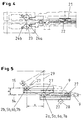
- the mechanism by which the feed rods 16 and the gripper rods 9 for a transport stroke or disengaged for an idle stroke in the other direction brought, is shown in Fig. 4.
- the feed rods 16 are pivotally mounted about their longitudinal axes 23 and are engaged with the gripper bars 9 or with these disengaged by the feed rods 16 between a position in which it with the gripper bars 9 in Are engaged and pivoted to a second position, in which they are disengaged from the gripper bars 9.
- the Feed rods 16 have two opposite one another Single wing 24a, 24b on -like a propeller-, wherein a wing 24a faces the gripper bars 9. In this Wings 24a are the recesses 17 for receiving the end regions 18 of the gripper bars 9 are provided.
- a drive device (not shown) can (Fig. 3) that the feed rods 16 along their Drives longitudinal axis to a reciprocation.
- a drive device a double cam gear can be provided be used as a transmission medium from the transmission to the feed rods Chains, toothed frames, steel ties, racks and the like are conceivable.
- the breakpoints are 2b, 5b, 6b, 7b of the gripper bars 9 of the return plane 15 to the stops 2a, 5a, 6a, 7a of the gripper bars 9 the feed plane 14 offset by the dimension x in the direction of the tray 7. This offset x is necessary to in the machining stations 5, 6 and 7 in the storage space for the necessary To create tool frames. If the feed rods 16 and the gripper bars 9 do not engage with each other are, the gripper bars 9 by index bolts 27th fixed locally, in particular to the processing stations maintain a defined position during processing.
- Index bolts 27 can be provided, either only the gripper bar 9 of the feed plane 14 or only the gripper bar 9 lock the return level 15, the gripper rods 9 corresponding recesses 28 for the index bolts 27 have. But it is also provided that an index bolt 27 between the upper and the lower gripper bar 9 is pushed and thereby fixed both at the same time. Only when the gripper rods 9 are locked by the index bolts 27 are, the gripper rods 9 from the feed rods 16 uncoupled and make the feed rods 16 one Idle stroke by a system length SL or by a distance between the processing stations in the direction of Appendix 2 in the case of Feed level 14 and in the direction of tray 7 in the case of Return level.
Landscapes
- Engineering & Computer Science (AREA)
- Mechanical Engineering (AREA)
- Discharge By Other Means (AREA)
- Feeding Of Articles By Means Other Than Belts Or Rollers (AREA)
- Details Of Cutting Devices (AREA)
- Folding Of Thin Sheet-Like Materials, Special Discharging Devices, And Others (AREA)
- Advancing Webs (AREA)
Applications Claiming Priority (2)
| Application Number | Priority Date | Filing Date | Title |
|---|---|---|---|
| DE19807587 | 1998-02-23 | ||
| DE19807587A DE19807587C1 (de) | 1998-02-23 | 1998-02-23 | Verfahren und Vorrichtung zur Bewegung von Greiferstangen in einer bogenverarbeitenden Maschine |
Publications (3)
| Publication Number | Publication Date |
|---|---|
| EP0937673A2 true EP0937673A2 (fr) | 1999-08-25 |
| EP0937673A3 EP0937673A3 (fr) | 2000-06-07 |
| EP0937673B1 EP0937673B1 (fr) | 2001-07-18 |
Family
ID=7858663
Family Applications (1)
| Application Number | Title | Priority Date | Filing Date |
|---|---|---|---|
| EP99102935A Expired - Lifetime EP0937673B1 (fr) | 1998-02-23 | 1999-02-13 | Procédé et dispositif pour déplacer des barres à pinces dans une machine de traitement de feuilles |
Country Status (6)
| Country | Link |
|---|---|
| US (1) | US6152441A (fr) |
| EP (1) | EP0937673B1 (fr) |
| JP (1) | JPH11278714A (fr) |
| KR (1) | KR19990072827A (fr) |
| DE (2) | DE19807587C1 (fr) |
| ES (1) | ES2161561T3 (fr) |
Families Citing this family (7)
| Publication number | Priority date | Publication date | Assignee | Title |
|---|---|---|---|---|
| US7017640B2 (en) * | 2001-02-09 | 2006-03-28 | Winter Steven B | Method and apparatus for manufacture of swatch-bearing sheets |
| DE602004011618T2 (de) * | 2004-10-15 | 2009-04-02 | Bobst S.A. | Verfahren und Vorrichtung zur Aufnahme eines Blattes in einer Maschine zur Bearbeitung von brettförmigem Gut |
| TWI275484B (en) * | 2004-10-15 | 2007-03-11 | Bobst Sa | Method and station for unblanked sheet delivery in a machine processing plate elements |
| DE102005024992B4 (de) * | 2005-06-01 | 2007-02-08 | Heidelberger Druckmaschinen Ag | Verfahren und Vorrichtung zum Fördern eines Bogens durch eine drucktechnische Maschine |
| US20080308997A1 (en) * | 2007-06-12 | 2008-12-18 | Prim Hall Enterprises, Inc. | Methods and systems for transferring stacked sheet material |
| DE102011018509A1 (de) * | 2011-04-23 | 2012-10-25 | Kolbus Gmbh & Co. Kg | Vorrichtung zum Zuführen von Buchblocks zu einer Buchbindemaschine |
| EP3461606B1 (fr) * | 2017-10-02 | 2021-04-28 | Kama GmbH | Machine à poinçonner ou à faire des empreintes et procédé de traitement de feuilles |
Family Cites Families (8)
| Publication number | Priority date | Publication date | Assignee | Title |
|---|---|---|---|---|
| US3809390A (en) * | 1972-01-12 | 1974-05-07 | Miller Printing Machinery Co | Sheet gripper apparatus for a cutting and creasing press |
| CA1163226A (fr) * | 1980-10-20 | 1984-03-06 | Calvin C. Williamson | Systeme de guidage a pinces de saisie pour toles |
| DE3617916A1 (de) * | 1986-05-28 | 1987-12-03 | Kiefel Hochfrequenz Paul | Einrichtung zum herstellen von zuschnitten fuer faltschachteln od. dgl. |
| ES2115991T3 (es) * | 1994-03-25 | 1998-07-01 | Ferag Ag | Instalacion para la union por encolado de productos de imprenta. |
| CH690097A5 (fr) * | 1994-05-04 | 2000-04-28 | Bobst Sa | Dispositif d'attache d'une barre de pinces à un train de chaînes au sein d'une machine de traitement d'éléments en plaque. |
| SE506416C2 (sv) * | 1995-02-24 | 1997-12-15 | Wamag Idab Ab | Förfarande och anordning för att identifiera och återfinna en gripare i en griparetransportör för tryckeriprodukter |
| CA2174076C (fr) * | 1996-04-12 | 2003-03-25 | Sylvain Rodier | Dispositif d'etamage en continu de boitiers dip |
| US5669754A (en) * | 1996-04-22 | 1997-09-23 | Advanced Dynamics Corporation Ltd. | Method and apparatus for collecting plates |
-
1998
- 1998-02-23 DE DE19807587A patent/DE19807587C1/de not_active Expired - Fee Related
-
1999
- 1999-02-13 DE DE59900155T patent/DE59900155D1/de not_active Expired - Fee Related
- 1999-02-13 ES ES99102935T patent/ES2161561T3/es not_active Expired - Lifetime
- 1999-02-13 EP EP99102935A patent/EP0937673B1/fr not_active Expired - Lifetime
- 1999-02-17 US US09/251,790 patent/US6152441A/en not_active Expired - Fee Related
- 1999-02-22 KR KR1019990005863A patent/KR19990072827A/ko not_active Ceased
- 1999-02-23 JP JP11045150A patent/JPH11278714A/ja active Pending
Also Published As
| Publication number | Publication date |
|---|---|
| ES2161561T3 (es) | 2001-12-01 |
| JPH11278714A (ja) | 1999-10-12 |
| DE59900155D1 (de) | 2001-08-23 |
| EP0937673B1 (fr) | 2001-07-18 |
| US6152441A (en) | 2000-11-28 |
| EP0937673A3 (fr) | 2000-06-07 |
| KR19990072827A (ko) | 1999-09-27 |
| DE19807587C1 (de) | 1999-04-29 |
Similar Documents
| Publication | Publication Date | Title |
|---|---|---|
| DE69501185T2 (de) | Ausbrechvorrichtung in einer Schneidevorrichtung | |
| DE3329900A1 (de) | Vorrichtung zum dreidimensionalen transfer von werkstuecken | |
| DE4100477A1 (de) | Vorrichtung zur behandlung von gegenstaenden | |
| EP3370892B1 (fr) | Système de préhension pour presse à plier | |
| DE102010004781A1 (de) | Trenn- und Abisoliereinrichtung für eine Kabelverarbeitungsmaschine | |
| WO1997046339A1 (fr) | Machine d'usinage pour pieces sous forme de plaques, notamment pour produire des bords plies sur des pieces en tole | |
| EP2158055B1 (fr) | Dispositif de sciage et procédé d'usinage par sciage d'une pièce à usiner | |
| EP0950623B1 (fr) | Dispositif pour le stockage et le déstockage d'unités de chargement | |
| WO2019036736A1 (fr) | Système de préparation destiné à fabriquer une tige d'enroulement pour un moteur électrique, et procédé de fabrication d'une tige d'enroulement | |
| DE69700291T2 (de) | Vorrichtung zum Ablängen und Formen von Stahlstäben, insbesondere von Betonbewehrungsstäben | |
| EP0937673B1 (fr) | Procédé et dispositif pour déplacer des barres à pinces dans une machine de traitement de feuilles | |
| DE2644900B2 (de) | Profiliermaschine | |
| DE69807723T2 (de) | Vorrichtung zum klemmen, führen und fördern der ränder einer mit schnitten versehenen folienbahn in einer maschine zum herstellen von streckmetall | |
| EP3715009B1 (fr) | Procédé de fabrication de grillage formant armature | |
| EP0164490B1 (fr) | Poinçonneuse avec magasin d'outils | |
| EP0647488A1 (fr) | Presse, presse à plusieurs étages ou machine de déformation pareille | |
| EP0774310A1 (fr) | Dispositif de transfert de ressorts à une machine d'assemblage | |
| CH634492A5 (de) | Verfahren und vorrichtung zum vereinzeln von ein loses buendel bildenden abgelaengten draehten, insbesondere zwecks drahtzufuhr zu einer gitterschweissmaschine. | |
| EP0633077B1 (fr) | Dispositif pour l'avance intermittente de pièces de travail | |
| EP1351783A1 (fr) | Dispositif de coupe transversale de bandes metalliques | |
| DE2839934A1 (de) | Vorschubeinrichtung | |
| DE69703978T2 (de) | Vorrichtung zum regeln der grösse eines werkzeugmaschinen-blechhalters | |
| EP0925126A1 (fr) | Machine a usiner des plats dotee d'une serre-flan reparti en segments | |
| DE2018950A1 (de) | Bearbeitungssystem fur die Her stellung von Gegenstanden | |
| EP1320432B1 (fr) | Dispositif de transfert |
Legal Events
| Date | Code | Title | Description |
|---|---|---|---|
| PUAI | Public reference made under article 153(3) epc to a published international application that has entered the european phase |
Free format text: ORIGINAL CODE: 0009012 |
|
| AK | Designated contracting states |
Kind code of ref document: A2 Designated state(s): CH DE ES FR GB IT LI |
|
| AX | Request for extension of the european patent |
Free format text: AL;LT;LV;MK;RO;SI |
|
| PUAL | Search report despatched |
Free format text: ORIGINAL CODE: 0009013 |
|
| AK | Designated contracting states |
Kind code of ref document: A3 Designated state(s): AT BE CH CY DE DK ES FI FR GB GR IE IT LI LU MC NL PT SE |
|
| AX | Request for extension of the european patent |
Free format text: AL;LT;LV;MK;RO;SI |
|
| 17P | Request for examination filed |
Effective date: 20000904 |
|
| GRAG | Despatch of communication of intention to grant |
Free format text: ORIGINAL CODE: EPIDOS AGRA |
|
| GRAG | Despatch of communication of intention to grant |
Free format text: ORIGINAL CODE: EPIDOS AGRA |
|
| GRAH | Despatch of communication of intention to grant a patent |
Free format text: ORIGINAL CODE: EPIDOS IGRA |
|
| 17Q | First examination report despatched |
Effective date: 20001122 |
|
| AKX | Designation fees paid |
Free format text: CH DE ES FR GB IT LI |
|
| GRAH | Despatch of communication of intention to grant a patent |
Free format text: ORIGINAL CODE: EPIDOS IGRA |
|
| GRAA | (expected) grant |
Free format text: ORIGINAL CODE: 0009210 |
|
| AK | Designated contracting states |
Kind code of ref document: B1 Designated state(s): CH DE ES FR GB IT LI |
|
| REG | Reference to a national code |
Ref country code: CH Ref legal event code: EP |
|
| REF | Corresponds to: |
Ref document number: 59900155 Country of ref document: DE Date of ref document: 20010823 |
|
| GBT | Gb: translation of ep patent filed (gb section 77(6)(a)/1977) |
Effective date: 20011009 |
|
| REG | Reference to a national code |
Ref country code: CH Ref legal event code: NV Representative=s name: LUCHS & PARTNER PATENTANWAELTE |
|
| REG | Reference to a national code |
Ref country code: ES Ref legal event code: FG2A Ref document number: 2161561 Country of ref document: ES Kind code of ref document: T3 |
|
| EN | Fr: translation not filed | ||
| REG | Reference to a national code |
Ref country code: GB Ref legal event code: IF02 |
|
| EN | Fr: translation not filed |
Free format text: BO 01/51 PAGES: 265, IL Y A LIEU DE SUPPRIMER: LA MENTION DE LA NON REMISE. LA REMISE EST PUBLIEE DANS LE PRESENT BOPI. |
|
| ET | Fr: translation filed | ||
| PLBE | No opposition filed within time limit |
Free format text: ORIGINAL CODE: 0009261 |
|
| STAA | Information on the status of an ep patent application or granted ep patent |
Free format text: STATUS: NO OPPOSITION FILED WITHIN TIME LIMIT |
|
| 26N | No opposition filed | ||
| PGFP | Annual fee paid to national office [announced via postgrant information from national office to epo] |
Ref country code: DE Payment date: 20050117 Year of fee payment: 7 |
|
| PGFP | Annual fee paid to national office [announced via postgrant information from national office to epo] |
Ref country code: GB Payment date: 20050201 Year of fee payment: 7 |
|
| PGFP | Annual fee paid to national office [announced via postgrant information from national office to epo] |
Ref country code: FR Payment date: 20050210 Year of fee payment: 7 |
|
| PGFP | Annual fee paid to national office [announced via postgrant information from national office to epo] |
Ref country code: CH Payment date: 20050216 Year of fee payment: 7 |
|
| PGFP | Annual fee paid to national office [announced via postgrant information from national office to epo] |
Ref country code: ES Payment date: 20050228 Year of fee payment: 7 |
|
| PG25 | Lapsed in a contracting state [announced via postgrant information from national office to epo] |
Ref country code: GB Free format text: LAPSE BECAUSE OF NON-PAYMENT OF DUE FEES Effective date: 20060213 |
|
| PG25 | Lapsed in a contracting state [announced via postgrant information from national office to epo] |
Ref country code: ES Free format text: LAPSE BECAUSE OF NON-PAYMENT OF DUE FEES Effective date: 20060214 |
|
| PG25 | Lapsed in a contracting state [announced via postgrant information from national office to epo] |
Ref country code: LI Free format text: LAPSE BECAUSE OF NON-PAYMENT OF DUE FEES Effective date: 20060228 Ref country code: CH Free format text: LAPSE BECAUSE OF NON-PAYMENT OF DUE FEES Effective date: 20060228 |
|
| PGFP | Annual fee paid to national office [announced via postgrant information from national office to epo] |
Ref country code: IT Payment date: 20060228 Year of fee payment: 8 |
|
| PG25 | Lapsed in a contracting state [announced via postgrant information from national office to epo] |
Ref country code: DE Free format text: LAPSE BECAUSE OF NON-PAYMENT OF DUE FEES Effective date: 20060901 |
|
| REG | Reference to a national code |
Ref country code: CH Ref legal event code: PL |
|
| GBPC | Gb: european patent ceased through non-payment of renewal fee |
Effective date: 20060213 |
|
| REG | Reference to a national code |
Ref country code: FR Ref legal event code: ST Effective date: 20061031 |
|
| REG | Reference to a national code |
Ref country code: ES Ref legal event code: FD2A Effective date: 20060214 |
|
| PG25 | Lapsed in a contracting state [announced via postgrant information from national office to epo] |
Ref country code: FR Free format text: LAPSE BECAUSE OF NON-PAYMENT OF DUE FEES Effective date: 20060228 |
|
| PG25 | Lapsed in a contracting state [announced via postgrant information from national office to epo] |
Ref country code: IT Free format text: LAPSE BECAUSE OF NON-PAYMENT OF DUE FEES Effective date: 20070213 |