EP0950623B1 - Dispositif pour le stockage et le déstockage d'unités de chargement - Google Patents
Dispositif pour le stockage et le déstockage d'unités de chargement Download PDFInfo
- Publication number
- EP0950623B1 EP0950623B1 EP99250119A EP99250119A EP0950623B1 EP 0950623 B1 EP0950623 B1 EP 0950623B1 EP 99250119 A EP99250119 A EP 99250119A EP 99250119 A EP99250119 A EP 99250119A EP 0950623 B1 EP0950623 B1 EP 0950623B1
- Authority
- EP
- European Patent Office
- Prior art keywords
- gripping
- mechanism according
- plate
- gripper
- longitudinal guides
- Prior art date
- Legal status (The legal status is an assumption and is not a legal conclusion. Google has not performed a legal analysis and makes no representation as to the accuracy of the status listed.)
- Expired - Lifetime
Links
- 238000003780 insertion Methods 0.000 title claims description 5
- 230000037431 insertion Effects 0.000 title claims description 5
- 238000000151 deposition Methods 0.000 claims 1
- 230000001360 synchronised effect Effects 0.000 description 5
- 238000010521 absorption reaction Methods 0.000 description 3
- 230000006378 damage Effects 0.000 description 2
- 230000000694 effects Effects 0.000 description 2
- 230000006978 adaptation Effects 0.000 description 1
- 230000006399 behavior Effects 0.000 description 1
- 239000000463 material Substances 0.000 description 1
- 238000000034 method Methods 0.000 description 1
Images


Classifications
-
- B—PERFORMING OPERATIONS; TRANSPORTING
- B65—CONVEYING; PACKING; STORING; HANDLING THIN OR FILAMENTARY MATERIAL
- B65G—TRANSPORT OR STORAGE DEVICES, e.g. CONVEYORS FOR LOADING OR TIPPING, SHOP CONVEYOR SYSTEMS OR PNEUMATIC TUBE CONVEYORS
- B65G1/00—Storing articles, individually or in orderly arrangement, in warehouses or magazines
- B65G1/02—Storage devices
- B65G1/04—Storage devices mechanical
- B65G1/0407—Storage devices mechanical using stacker cranes
- B65G1/0435—Storage devices mechanical using stacker cranes with pulling or pushing means on either stacking crane or stacking area
-
- Y—GENERAL TAGGING OF NEW TECHNOLOGICAL DEVELOPMENTS; GENERAL TAGGING OF CROSS-SECTIONAL TECHNOLOGIES SPANNING OVER SEVERAL SECTIONS OF THE IPC; TECHNICAL SUBJECTS COVERED BY FORMER USPC CROSS-REFERENCE ART COLLECTIONS [XRACs] AND DIGESTS
- Y10—TECHNICAL SUBJECTS COVERED BY FORMER USPC
- Y10S—TECHNICAL SUBJECTS COVERED BY FORMER USPC CROSS-REFERENCE ART COLLECTIONS [XRACs] AND DIGESTS
- Y10S294/00—Handling: hand and hoist-line implements
- Y10S294/902—Gripping element
Definitions
- the invention relates to a device for lifting and delivering loads Loading units according to the preamble of claim 1.
- a generic device for load absorption and Load delivery of containers known, which are arranged in compartments of a rack system.
- the device has grippers which are arranged in parallel to one another horizontal longitudinal guides are guided.
- the grippers are next to the side surfaces of the container movable and applied to the respective side surface of the Container can be created.
- a gripping surface is provided on each gripper.
- the Gripping surfaces of both grippers lie opposite each other and are parallel to each other aligned.
- the gripping elements are synchronized with the container moved against each other. To cushion the contact pressure is a spring bearing Gripping elements provided.
- the disadvantage of this device is that a special container shape, in particular in the gripping area of the gripping elements.
- the containers must be over it also have approximately the same shape and strength.
- Especially heavy Cardboard boxes can only be gripped if the contact pressure of the grippers is relative is chosen large.
- the object of the invention is a device for load absorption and load delivery of loading units to create loading units of different shape and Strength can be gripped safely.
- each gripper has several differently trained Has synchronously attachable gripping elements on the side surfaces. That way it is possible that the device in a relatively large area container different shape and strength can grip securely.
- the gripping elements comprise at least two differently designed gripping plates, each prefer to be able to safely hold a type of loading unit.
- the gripping elements comprise at least two differently designed gripping plates, each prefer to be able to safely hold a type of loading unit.
- a first is provided for loading units with firm, flat side surfaces Gripping plate with a roughened flat surface designed as a gripping surface.
- the thickness of the second gripping plate is expediently smaller than the thickness of the first, so that the sawtooth-shaped depressions only take effect when the loading unit yields to the side surfaces due to the contact pressure.
- a third gripping element is used to reinforce the gripping effect proposed, namely a spike-like projection that at least one of the Gripping plates arranged, perpendicular to this and the opposite Gripper extends.
- the length of the mandrel should be chosen slightly larger than the thickness of the first gripping plate are so that they always slightly positive in the side surface of the bearing unit intervenes.
- each gripper one for opposite gripper extending back plate with a remote has vertical contact surfaces in the direction of insertion. The contact plate slides into the Loading unit when storing in the shelf compartment, so that the gripping elements are effective get supported.
- the gripper constructed symmetrically with respect to the contact plate, d. H. that in Viewed in the same direction on both sides of the contact plate Gripping elements are provided in the same arrangement.
- a uniform synchronous system results when the longitudinal guide to the system the gripping elements on the loading unit are mutually synchronously movable.
- a simple solution provides that the end not connected to the drive Spindle is mounted in a spindle nut fixedly arranged on the longitudinal guide.
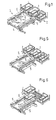
- the gripping device 4 for removing the loading unit 1 before Shelf 2 is arranged.
- the gripping device 4 consists of two in one horizontal plane parallel to each other longitudinal guides 5. At each Longitudinal guide 5 is in each case a gripper 6 guided in the longitudinal direction thereof. The grippers 6 of the two longitudinal guides 5 are opposite each other and are in their ready position in Fig. 1.
- FIGs 2 and 3 show a specially designed gripper in two different views.
- This gripper 6 has a total of four as gripping elements Gripping plates 7, 8, 9, 10 on the one behind the other flat on the same side of a Base plate 11 are arranged.
- a vertical contact plate 12 is vertical attached to the base plate 11 and the gripping plates 7, 8, 9, 10, wherein according to the Top view in Fig. 3 left of the contact plate 12 two gripping plates 7, 8 and two on the right Gripping plates 9, 10 are arranged.
- the contact plate 12 continues to face each other facing vertical contact surfaces 13 which are perpendicular to the gripping plates 7, 8, 9, 10 run. 3, the gripping plates 7, 10 roughened while the gripping plates 8, 9 with sawtooth-shaped vertical Depressions are provided.
- Each sawtooth of the gripping plates 8, 9 has two vertical outer surfaces 14, 15, wherein the outer surface 14 perpendicular to the base plate 11 or to the gripping plate 7, 10 of the Gripper 6 is aligned.
- the outer surface 15, on the other hand, is oblique to the base plate 11 or to the gripping plate 7, 10, so that the special shown in Fig. 3 Sawtooth shape results.
- 3 also shows a perpendicular to the gripping plates 7, 10 to the other gripper 6 oriented mandrel 16 on both sides of the contact plate 12th
- the thickness of the gripping plates 7, 10 and 8, 9 is different. So is the thickness of the gripping plates 7.10 is approximately one millimeter larger than that of the gripping plates 8.9.
- the thickness of the gripping plates 8.9 relates to the height of the teeth, measured at the top.
- the length of the mandrels 16 is approximately one millimeter larger than the thickness the gripping plates 7, 10.
- the tips of the sawtooth-shaped protrude the least Gripping plates 8, 9 in the space between the opposing grippers 6 into it.
- the gripping plates 7, 10, 8, 9 of each gripper 6 are also each in one common vertical plane.
- the gripping plates 7 of different thicknesses, 10 and 8.9 and the length of the mandrels 16 chosen in relation thereto serve the better Adaptation to different loading units 1, especially if for the Loading units 1 different material is used. That's how they are sawtooth-shaped gripping plates, for example only in cardboard boxes and the like effective, while the mandrels 16 are always involved in gripping.
- FIG. 4 shows a top view of the gripping device according to FIG. 1, the grippers 6, are again only shown schematically.
- the two longitudinal guides 5 are open transversely to these arranged cross beams 17 supported longitudinally and over a spindle 18 connected to each other.
- One end of the spindle 18 is one Servomotor 19 driven and is on this side on the associated longitudinal guide 5 freely rotatable.
- the opposite end of the spindle 18 is in one Spindle nut 18a rotatably mounted on the opposite longitudinal guide 5 is rotatably attached.
- the servo motor 19 both longitudinal guides moved towards each other.
- the spindle 18 can of course also be a right and right hand side wear a left-hand thread on the other side.
- the Double lever 21 can be dispensed with.
- two spindles can also be used one motor each can be used.
- the transverse movement is further - instead of using a Spindle - can also be carried out using a toothed belt or chain.
- the transverse drive is pneumatic.
- the two grippers 6 shown in FIG. 4 are in a longitudinal groove of the associated one Longitudinal guide 5 synchronously by means of a toothed belt (both not shown) slidably guided.
- the two grippers 6 are synchronized via a additional connecting shaft arranged transversely to the longitudinal guides 5 (not shown), the length of which can be changed in a known manner.
- FIG. 5 shows, together with FIGS. 1 and 6, the removal of a loading unit 1.
- the longitudinal guides 5 were previously in the servo motor 19 in approximately moved to the width of the loading unit 1, leaving one Excess of a few centimeters. Then the synchronous shift took place of the two grippers 6 to the loading unit 1 down to their end positions, where they over partially extend the outer contour of the gripping device into the shelf. When their end positions are reached, the longitudinal guides 5 and in this way the gripper 6 moves synchronously against each other, so that the parallel to each other and in also substantially aligned with the side surfaces of the loading unit 1 Gripping plates 9,10 are placed on the side surfaces of the loading unit 1.
- the so grasped Loading unit 1 is then by pulling the gripper 6 out of the rack compartment 2 pulled.
Landscapes
- Engineering & Computer Science (AREA)
- Mechanical Engineering (AREA)
- Manipulator (AREA)
- Warehouses Or Storage Devices (AREA)
Claims (14)
- Dispositif (3) pour recevoir et évacuer des unités de chargement (1), en particulier dans des rayonnages (2), comportant un dispositif de prise (4) pour l'unité de chargement, dont les pinces (6) sont guidées dans des guides longitudinaux (5) agencés parallèlement les uns aux autres, dans un plan horizontal, sont déplaçables dans la direction d'introduction, de façon bilatérale, à côté des surfaces latérales de l'unité de chargement (1), et, pour la saisie, peuvent être appliquées, sous l'action d'une force, contre la surface latérale à chaque fois opposée de l'unité de chargement, au moins une plaque de saisie étant prévue sur chaque pince (6) et les plaques de saisie des deux pinces étant opposées l'une à l'autre et étant orientées parallèlement l'une à l'autre,
caractérisé en ce que chaque pince (6) présente au moins deux éléments de saisie, réalisés de façon différente, pouvant être appliqués de façon synchrone contre les surfaces latérales. - Dispositif selon la revendication 1,
caractérisé en ce que les éléments de saisie comportent au moins deux plaques de saisie (7, 8, 9, 10). - Dispositif selon la revendication 2,
caractérisé en ce qu'une première plaque de saisie (7, 10) est réalisée comme plaque de saisie ayant une surface plane granulée. - Dispositif selon la revendication 2,
caractérisé en ce que, dans une seconde plaque de saisie (8, 9), une pluralité d'évidements verticaux en forme de dents de scie sont réalisés comme plaque de saisie. - Dispositif selon la revendication 4,
caractérisé en ce que l'épaisseur de la seconde plaque de saisie (8, 9) est plus petite que l'épaisseur de la première plaque de saisie (7, 10). - Dispositif selon une des revendications 1 à 5,
caractérisé en ce que, sur au moins une des plaques de saisie (7, 8, 9, 10), au moins une saillie du type mandrin (mandrin 16), s'étendant perpendiculairement à celle-ci et vers la pince opposée (6), est agencée. - Dispositif selon la revendication 6,
caractérisé en ce que la longueur du mandrin (16) est plus grande que l'épaisseur de la première plaque de saisie (7, 10). - Dispositif selon une des revendications 1 à 7,
caractérisé en ce que chaque pince (6) présente une plaque d'appui (12) s'étendant vers la pince opposée (6) ayant des surfaces d'appui (13) verticales, écartées l'une de l'autre, dans la direction d'insertion. - Dispositif selon la revendication 8,
caractérisé en ce que, dans la direction d'insertion, sur les deux côtés de la plaque d'appui (12), à chaque fois les mêmes éléments de saisie sont prévus dans le même agencement. - Dispositif selon une des revendications 1 à 9,
caractérisé en ce que les guides longitudinaux (5), pour l'appui des éléments de saisie contre l'unité de chargement (1), peuvent être déplacés de façon synchrone l'un par rapport à l'autre. - Dispositif selon une des revendications 1 à 10,
caractérisé en ce que les guides longitudinaux (5) sont reliés ensemble par l'intermédiaire d'un axe entraíné (18), dont les extrémités sont montées de façon rotative, à chaque fois, sur un des guides longitudinaux (5). - Dispositif selon la revendication 11,
caractérisé en ce que l'extrémité, non reliée à l'entraínement, d'un axe (18) est montée dans un écrou (18a) agencé de façon fixe sur le guide longitudinal (5). - Dispositif selon une des revendications 1 à 12,
caractérisé en ce que l'entraínement est formé par un servomoteur (19), qui, lorsqu'une valeur de courant de moteur prédéterminée est atteinte, peut être limité automatiquement à cette valeur. - Dispositif selon une des revendications 1 à 13,
caractérisé en ce que les guides longitudinaux (5) sont reliés ensemble de façon articulée par l'intermédiaire d'un levier double (21) monté de façon rotative, à chaque fois, de façon centrale par rapport aux guides longitudinaux (5), sur le bâti (20).
Applications Claiming Priority (2)
| Application Number | Priority Date | Filing Date | Title |
|---|---|---|---|
| DE19817935A DE19817935A1 (de) | 1998-04-17 | 1998-04-17 | Aufnahmevorrichtung zur Lastaufnahme und Lastabgabe von Ladeeinheiten |
| DE19817935 | 1998-04-17 |
Publications (2)
| Publication Number | Publication Date |
|---|---|
| EP0950623A1 EP0950623A1 (fr) | 1999-10-20 |
| EP0950623B1 true EP0950623B1 (fr) | 2003-08-13 |
Family
ID=7865414
Family Applications (1)
| Application Number | Title | Priority Date | Filing Date |
|---|---|---|---|
| EP99250119A Expired - Lifetime EP0950623B1 (fr) | 1998-04-17 | 1999-04-14 | Dispositif pour le stockage et le déstockage d'unités de chargement |
Country Status (4)
| Country | Link |
|---|---|
| US (1) | US6234550B1 (fr) |
| EP (1) | EP0950623B1 (fr) |
| DE (2) | DE19817935A1 (fr) |
| ES (1) | ES2200466T3 (fr) |
Families Citing this family (16)
| Publication number | Priority date | Publication date | Assignee | Title |
|---|---|---|---|---|
| DE10140643B4 (de) * | 2001-04-27 | 2007-04-05 | Kht Kommissionier- Und Handhabungstechnik Gmbh | Regallagersystem |
| DE10142838A1 (de) * | 2001-08-23 | 2003-03-27 | Kht Kommissionier & Handhabung | Regallager für quaderförmige Behälter, insbesondere Standardkisten |
| US6595736B2 (en) * | 2001-09-11 | 2003-07-22 | Systems & Electronics, Inc. | Unloader retaining arm assembly |
| US9744676B2 (en) * | 2009-10-20 | 2017-08-29 | Illinois Tool Works Inc. | Dual side acting hydraulic grips synchronization |
| JP5970002B2 (ja) | 2011-03-03 | 2016-08-17 | バイエル・インテレクチュアル・プロパティ・ゲゼルシャフト・ミット・ベシュレンクテル・ハフツングBayer Intellectual Property GmbH | 4−ヒドロキシ−2−オキソ−2,5−ジヒドロフラン−3−カルボン酸化合物のナトリウム塩またはカリウム塩の製造方法 |
| AT511641A3 (de) * | 2011-07-08 | 2013-07-15 | Tgw Mechanics Gmbh | Lastaufnahmemittel zum ein- und auslagern von ladegütern |
| US9351569B1 (en) * | 2013-02-11 | 2016-05-31 | Automated Cells and Equipment, Inc. | Parts supply drawer system for robot assisted manufacturing |
| CN103771067B (zh) * | 2014-01-09 | 2016-03-16 | 苏州艾隆科技股份有限公司 | 药筐传送系统 |
| US10294027B2 (en) * | 2015-01-09 | 2019-05-21 | Carefusion Germany 326 Gmbh | Operating device for an order-picking apparatus |
| JP6210091B2 (ja) * | 2015-07-10 | 2017-10-11 | 村田機械株式会社 | 移載装置及び搬送システム |
| JP6930522B2 (ja) * | 2016-02-18 | 2021-09-01 | 株式会社ダイフク | 物品搬送装置 |
| JP6729491B2 (ja) * | 2017-05-25 | 2020-07-22 | 株式会社ダイフク | 物品移載装置 |
| FR3072371A1 (fr) * | 2017-10-12 | 2019-04-19 | Exotec Solutions | Systeme de stockage et de transport d'objets entreposes dans des rayonnages d'un entrepot |
| JP7571597B2 (ja) | 2021-02-15 | 2024-10-23 | トヨタ自動車株式会社 | 運搬システム |
| JP7563219B2 (ja) * | 2021-02-15 | 2024-10-08 | トヨタ自動車株式会社 | 運搬システム |
| AU2022278594B2 (en) * | 2021-05-17 | 2025-09-25 | Ocado Innovation Limited | Mechanical handling apparatus |
Family Cites Families (14)
| Publication number | Priority date | Publication date | Assignee | Title |
|---|---|---|---|---|
| US2740540A (en) * | 1952-11-12 | 1956-04-03 | American Steel Foundries | Shell transfer mechanism |
| US2921701A (en) * | 1954-06-14 | 1960-01-19 | Texas Bitulithic Company | Material handling device |
| US4305692A (en) * | 1975-06-24 | 1981-12-15 | Brauer Edwin H | Mold handler |
| FR2431980A1 (fr) * | 1978-07-28 | 1980-02-22 | Minato Exploitation | Dispositif et procede de conditionnement de produits tels que des blocs de beton, pour la realisation de palettes de produits, et palettes de produits ainsi obtenues |
| DE3324349C1 (de) * | 1983-07-06 | 1984-11-22 | Mannesmann AG, 4000 Düsseldorf | Regalanlage |
| US4735452A (en) * | 1986-12-19 | 1988-04-05 | Texas Instruments Incorporated | Article gripper assembly |
| GB2246119B (en) * | 1990-07-12 | 1994-05-04 | Paul Andrew Coulstock | Improvements in and relating to apparatus for manoeuvring a wheeled vehicle |
| US5588688A (en) * | 1990-08-06 | 1996-12-31 | Sarcos, Inc. | Robotic grasping apparatus |
| DE9101201U1 (de) | 1991-02-02 | 1992-02-13 | Robotech Logistiksysteme GmbH, Hörbranz | Hubwagen eines Regalförderzeuges |
| US5271706A (en) * | 1991-10-31 | 1993-12-21 | Hkm Corporation | Self-loading paper transport system |
| US5449262A (en) * | 1994-05-26 | 1995-09-12 | Diamond Machine Co. | Inserter/extractor used with carousel of storage bins |
| DE4425127A1 (de) * | 1994-07-15 | 1996-01-18 | Dreier Systemtechnik Ag | Lageranlage zum Kommissionieren |
| EP0733563A1 (fr) | 1995-03-22 | 1996-09-25 | Toyokanetsu Kabushiki Kaisha | Equipement de manutention et de stockage pour marchandises |
| DE19613707C2 (de) | 1996-03-26 | 2002-11-21 | Siemens Ag | Vorrichtung zur Lastaufnahme oder Lastabgabe |
-
1998
- 1998-04-17 DE DE19817935A patent/DE19817935A1/de not_active Withdrawn
-
1999
- 1999-03-22 US US09/274,420 patent/US6234550B1/en not_active Expired - Lifetime
- 1999-04-14 EP EP99250119A patent/EP0950623B1/fr not_active Expired - Lifetime
- 1999-04-14 ES ES99250119T patent/ES2200466T3/es not_active Expired - Lifetime
- 1999-04-14 DE DE59906557T patent/DE59906557D1/de not_active Expired - Lifetime
Also Published As
| Publication number | Publication date |
|---|---|
| EP0950623A1 (fr) | 1999-10-20 |
| DE19817935A1 (de) | 1999-11-04 |
| ES2200466T3 (es) | 2004-03-01 |
| US6234550B1 (en) | 2001-05-22 |
| DE59906557D1 (de) | 2003-09-18 |
Similar Documents
| Publication | Publication Date | Title |
|---|---|---|
| EP0950623B1 (fr) | Dispositif pour le stockage et le déstockage d'unités de chargement | |
| DE3908496C2 (de) | Handhabungsvorrichtung für eine Biegemaschine, Verfahren zur Umkehrung der Lage eines Werkstückes in einem Biegeverfahren und Biegemaschine | |
| DE2918687C2 (fr) | ||
| EP0453933B1 (fr) | Dispositif pour couper des produits lamellaires empilés | |
| DE2708457A1 (de) | Transportmechanismus zur verwendung in schmiedemaschinen | |
| DE3587327T2 (de) | Abkantpresse. | |
| DE4329179A1 (de) | Maschine zum Umsetzen von Artikeln in eine Verpackungseinheit | |
| EP3566985B1 (fr) | Dispositif d'empilement de plateaux pourvu d'un moyen de décharge | |
| DE3404553C2 (de) | Handhabungseinrichtung, insbesondere zum Be- und Entladen von Werkzeugmaschinen | |
| DE2441965A1 (de) | Anordnung zum bedienen insbesondere einer einseitig offenen presse | |
| EP4112513B1 (fr) | Système doté d'un dispositif d'appréhension | |
| WO2000043140A1 (fr) | Cintreuse | |
| DE68909272T2 (de) | Vorrichtung zum vorder- und rückseitigen Greifen und Vorwärtsbewegen einer erweichten, zu formenden Kunststoffolie. | |
| DE3618622C2 (fr) | ||
| WO2000043142A2 (fr) | Cintreuse | |
| DE2701443C2 (de) | Verpackungsmaschine | |
| DE2849751C2 (de) | Vorrichtung zum Vereinzeln von ein loses Bündel bildenden abgelängten Drähten, insbesondere zwechs Drahtzufuhr zu einer Verarbeitungsmaschine | |
| EP0633077B1 (fr) | Dispositif pour l'avance intermittente de pièces de travail | |
| DE19807587C1 (de) | Verfahren und Vorrichtung zur Bewegung von Greiferstangen in einer bogenverarbeitenden Maschine | |
| DD229325A5 (de) | Betaetigungsvorrichtung zur verwendung in einer giessereianlage | |
| DE69703978T2 (de) | Vorrichtung zum regeln der grösse eines werkzeugmaschinen-blechhalters | |
| WO2020020727A1 (fr) | Système de machine de traitement de câbles et procédé pour prélever un ou plusieurs câbles dans un bac de prélèvement d'un système de machine de traitement de câbles | |
| DE3814177A1 (de) | Klemmeinrichtung bei einschubaggregaten fuer aufteilanlagen zum aufteilen von plattenfoermigen werkstuecken | |
| DE2538650A1 (de) | Transportmechanismus fuer eine quertransportpresse | |
| DE2757516C2 (de) | Flaschenhalterahmen zum gleichzeitigen bündelweisen Um- und Einsetzen von in zur Anförderrichtung parallelen Reihen aufgestauten Flaschen u.dgl. in Kisten, Kästen, Harasse und dgl. |
Legal Events
| Date | Code | Title | Description |
|---|---|---|---|
| PUAI | Public reference made under article 153(3) epc to a published international application that has entered the european phase |
Free format text: ORIGINAL CODE: 0009012 |
|
| AK | Designated contracting states |
Kind code of ref document: A1 Designated state(s): DE ES FR GB IT |
|
| AX | Request for extension of the european patent |
Free format text: AL;LT;LV;MK;RO;SI |
|
| 17P | Request for examination filed |
Effective date: 19991007 |
|
| AKX | Designation fees paid |
Free format text: DE ES FR GB IT |
|
| GRAG | Despatch of communication of intention to grant |
Free format text: ORIGINAL CODE: EPIDOS AGRA |
|
| 17Q | First examination report despatched |
Effective date: 20010314 |
|
| GRAG | Despatch of communication of intention to grant |
Free format text: ORIGINAL CODE: EPIDOS AGRA |
|
| GRAH | Despatch of communication of intention to grant a patent |
Free format text: ORIGINAL CODE: EPIDOS IGRA |
|
| GRAH | Despatch of communication of intention to grant a patent |
Free format text: ORIGINAL CODE: EPIDOS IGRA |
|
| RAP1 | Party data changed (applicant data changed or rights of an application transferred) |
Owner name: SIEMENS AKTIENGESELLSCHAFT |
|
| GRAA | (expected) grant |
Free format text: ORIGINAL CODE: 0009210 |
|
| AK | Designated contracting states |
Designated state(s): DE ES FR GB IT |
|
| REG | Reference to a national code |
Ref country code: GB Ref legal event code: FG4D Free format text: NOT ENGLISH |
|
| GBT | Gb: translation of ep patent filed (gb section 77(6)(a)/1977) | ||
| REF | Corresponds to: |
Ref document number: 59906557 Country of ref document: DE Date of ref document: 20030918 Kind code of ref document: P |
|
| REG | Reference to a national code |
Ref country code: ES Ref legal event code: FG2A Ref document number: 2200466 Country of ref document: ES Kind code of ref document: T3 |
|
| ET | Fr: translation filed | ||
| PLBE | No opposition filed within time limit |
Free format text: ORIGINAL CODE: 0009261 |
|
| STAA | Information on the status of an ep patent application or granted ep patent |
Free format text: STATUS: NO OPPOSITION FILED WITHIN TIME LIMIT |
|
| 26N | No opposition filed |
Effective date: 20040514 |
|
| REG | Reference to a national code |
Ref country code: GB Ref legal event code: 732E Free format text: REGISTERED BETWEEN 20110120 AND 20110126 |
|
| REG | Reference to a national code |
Ref country code: FR Ref legal event code: TP |
|
| REG | Reference to a national code |
Ref country code: ES Ref legal event code: PC2A Owner name: DEMATIC GMBH Effective date: 20110418 |
|
| PGFP | Annual fee paid to national office [announced via postgrant information from national office to epo] |
Ref country code: GB Payment date: 20140422 Year of fee payment: 16 |
|
| PGFP | Annual fee paid to national office [announced via postgrant information from national office to epo] |
Ref country code: IT Payment date: 20140430 Year of fee payment: 16 Ref country code: FR Payment date: 20140422 Year of fee payment: 16 Ref country code: DE Payment date: 20140418 Year of fee payment: 16 Ref country code: ES Payment date: 20140428 Year of fee payment: 16 |
|
| REG | Reference to a national code |
Ref country code: DE Ref legal event code: R119 Ref document number: 59906557 Country of ref document: DE |
|
| GBPC | Gb: european patent ceased through non-payment of renewal fee |
Effective date: 20150414 |
|
| PG25 | Lapsed in a contracting state [announced via postgrant information from national office to epo] |
Ref country code: GB Free format text: LAPSE BECAUSE OF NON-PAYMENT OF DUE FEES Effective date: 20150414 Ref country code: DE Free format text: LAPSE BECAUSE OF NON-PAYMENT OF DUE FEES Effective date: 20151103 Ref country code: IT Free format text: LAPSE BECAUSE OF NON-PAYMENT OF DUE FEES Effective date: 20150414 |
|
| REG | Reference to a national code |
Ref country code: FR Ref legal event code: ST Effective date: 20151231 |
|
| PG25 | Lapsed in a contracting state [announced via postgrant information from national office to epo] |
Ref country code: FR Free format text: LAPSE BECAUSE OF NON-PAYMENT OF DUE FEES Effective date: 20150430 |
|
| PG25 | Lapsed in a contracting state [announced via postgrant information from national office to epo] |
Ref country code: ES Free format text: LAPSE BECAUSE OF NON-PAYMENT OF DUE FEES Effective date: 20150415 |
|
| REG | Reference to a national code |
Ref country code: ES Ref legal event code: FD2A Effective date: 20180705 |