EP0937868A1 - Support pour le montage d'un filtre à huile - Google Patents
Support pour le montage d'un filtre à huile Download PDFInfo
- Publication number
- EP0937868A1 EP0937868A1 EP99301156A EP99301156A EP0937868A1 EP 0937868 A1 EP0937868 A1 EP 0937868A1 EP 99301156 A EP99301156 A EP 99301156A EP 99301156 A EP99301156 A EP 99301156A EP 0937868 A1 EP0937868 A1 EP 0937868A1
- Authority
- EP
- European Patent Office
- Prior art keywords
- cut
- housing
- drain
- outs
- filter unit
- Prior art date
- Legal status (The legal status is an assumption and is not a legal conclusion. Google has not performed a legal analysis and makes no representation as to the accuracy of the status listed.)
- Granted
Links
- 239000003921 oil Substances 0.000 claims description 44
- 239000010705 motor oil Substances 0.000 claims description 10
- 238000010276 construction Methods 0.000 abstract description 2
- 238000005461 lubrication Methods 0.000 description 11
- 238000004519 manufacturing process Methods 0.000 description 3
- 238000002485 combustion reaction Methods 0.000 description 2
- 238000001914 filtration Methods 0.000 description 2
- 230000004048 modification Effects 0.000 description 1
- 238000012986 modification Methods 0.000 description 1
- 239000012466 permeate Substances 0.000 description 1
Images




Classifications
-
- F—MECHANICAL ENGINEERING; LIGHTING; HEATING; WEAPONS; BLASTING
- F01—MACHINES OR ENGINES IN GENERAL; ENGINE PLANTS IN GENERAL; STEAM ENGINES
- F01M—LUBRICATING OF MACHINES OR ENGINES IN GENERAL; LUBRICATING INTERNAL COMBUSTION ENGINES; CRANKCASE VENTILATING
- F01M11/00—Component parts, details or accessories, not provided for in, or of interest apart from, groups F01M1/00 - F01M9/00
- F01M11/03—Mounting or connecting of lubricant purifying means relative to the machine or engine; Details of lubricant purifying means
-
- B—PERFORMING OPERATIONS; TRANSPORTING
- B01—PHYSICAL OR CHEMICAL PROCESSES OR APPARATUS IN GENERAL
- B01D—SEPARATION
- B01D29/00—Filters with filtering elements stationary during filtration, e.g. pressure or suction filters, not covered by groups B01D24/00 - B01D27/00; Filtering elements therefor
- B01D29/11—Filters with filtering elements stationary during filtration, e.g. pressure or suction filters, not covered by groups B01D24/00 - B01D27/00; Filtering elements therefor with bag, cage, hose, tube, sleeve or like filtering elements
- B01D29/13—Supported filter elements
- B01D29/15—Supported filter elements arranged for inward flow filtration
- B01D29/21—Supported filter elements arranged for inward flow filtration with corrugated, folded or wound sheets
-
- B—PERFORMING OPERATIONS; TRANSPORTING
- B01—PHYSICAL OR CHEMICAL PROCESSES OR APPARATUS IN GENERAL
- B01D—SEPARATION
- B01D29/00—Filters with filtering elements stationary during filtration, e.g. pressure or suction filters, not covered by groups B01D24/00 - B01D27/00; Filtering elements therefor
- B01D29/96—Filters with filtering elements stationary during filtration, e.g. pressure or suction filters, not covered by groups B01D24/00 - B01D27/00; Filtering elements therefor in which the filtering elements are moved between filtering operations; Particular measures for removing or replacing the filtering elements; Transport systems for filters
-
- B—PERFORMING OPERATIONS; TRANSPORTING
- B01—PHYSICAL OR CHEMICAL PROCESSES OR APPARATUS IN GENERAL
- B01D—SEPARATION
- B01D35/00—Filtering devices having features not specifically covered by groups B01D24/00 - B01D33/00, or for applications not specifically covered by groups B01D24/00 - B01D33/00; Auxiliary devices for filtration; Filter housing constructions
- B01D35/14—Safety devices specially adapted for filtration; Devices for indicating clogging
- B01D35/147—Bypass or safety valves
-
- B—PERFORMING OPERATIONS; TRANSPORTING
- B01—PHYSICAL OR CHEMICAL PROCESSES OR APPARATUS IN GENERAL
- B01D—SEPARATION
- B01D35/00—Filtering devices having features not specifically covered by groups B01D24/00 - B01D33/00, or for applications not specifically covered by groups B01D24/00 - B01D33/00; Auxiliary devices for filtration; Filter housing constructions
- B01D35/16—Cleaning-out devices, e.g. for removing the cake from the filter casing or for evacuating the last remnants of liquid
-
- B—PERFORMING OPERATIONS; TRANSPORTING
- B01—PHYSICAL OR CHEMICAL PROCESSES OR APPARATUS IN GENERAL
- B01D—SEPARATION
- B01D35/00—Filtering devices having features not specifically covered by groups B01D24/00 - B01D33/00, or for applications not specifically covered by groups B01D24/00 - B01D33/00; Auxiliary devices for filtration; Filter housing constructions
- B01D35/30—Filter housing constructions
-
- B—PERFORMING OPERATIONS; TRANSPORTING
- B01—PHYSICAL OR CHEMICAL PROCESSES OR APPARATUS IN GENERAL
- B01D—SEPARATION
- B01D2201/00—Details relating to filtering apparatus
- B01D2201/40—Special measures for connecting different parts of the filter
- B01D2201/4023—Means for connecting filter housings to supports
-
- B—PERFORMING OPERATIONS; TRANSPORTING
- B01—PHYSICAL OR CHEMICAL PROCESSES OR APPARATUS IN GENERAL
- B01D—SEPARATION
- B01D2201/00—Details relating to filtering apparatus
- B01D2201/40—Special measures for connecting different parts of the filter
- B01D2201/4084—Snap or Seeger ring connecting means
Definitions
- This invention relates to a fixing structure of an oil filter to an internal combustion engine.
- a filter unit fitted to an internal combustion engine for filtering the lubrication oil generally comprises a filter housing and a filter element accommodated therein.
- the lubrication oil led into the housing from the engine is filtered by the filter element and returns to the inside of the engine.
- the filter unit is filled with lubrication oil while in operation, the lubrication oil may flow out and scatter when the filter unit is removed from the engine for replacement.
- Tokkai Hei 9-173716 published by the Japanese Patent Office in 1997, discloses to provide a drain plug at the bottom of the filter housing.
- the drain plug is removed, thereby evacuating the filter unit, and then the empty filter unit is removed from the engine.
- this invention provides a fixing structure of an engine oil filter unit, comprising a bracket fixed to an engine, the bracket comprising a cylindrical part having an inner circumference, a female screw formed on the inner circumference and a first drain element formed in female screw, and a housing which accommodates a filter element and is to be filled with oil, the housing having a cylindrical wall with an outer circumference, a male screw formed on the outer circumference to be engaged with the female screw, and a second drain element being formed in the male screw.
- the first and second drain elements are arranged to form a drain passage which drains oil in the housing to the outside when the first drain element meets the second drain element according to the relative rotation of the cylindrical part and the housing.
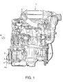
- Fig. 1 is a front elevation of an engine equipped with a filter unit, according to this invention.
- Fig. 2 is a side elevation of the engine viewed from the direction A of Fig. 1.
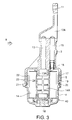
- Fig. 3 is a vertical sectional view of the filter unit and a bracket,according to this invention.
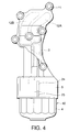
- Fig. 4 is a side elevation of the filter unit and bracket viewed from the direction B of Fig. 3.
- Fig. 5 is a horizontal sectional view of the filter unit.
- Fig. 6 is a side elevation of an upper part of the filter unit.
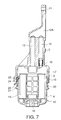
- Fig. 7 is a vertical sectional view of the filter unit draining oil therefrom.
- Fig. 8 is an under view of a filter housing.
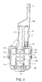
- Fig. 9 is similar to Fig. 3, but showing a second embodiment of this invention.
- Fig. 10 is similar to Fig. 5, but showing the second embodiment
- a filter housing 4 of a filter unit 40 is fitted to a cylinder block 2 of a vehicle engine 1 via a bracket 3.
- the filter unit 40 comprises a filter housing 4 and a filter element 14 accommodated therein.
- the bracket 3 comprises a cylindrical holder 5 at its lower end.
- the holder 5 has an opening downward and has a female screw 17 on its inner circumference.
- the filter housing 4 has a male screw 19 on its outer circumference.
- the upper part of the filter housing 4 is first inserted into the opening of the holder 5, then the housing 4 is turned so that the male screw 19 is engaged with the female screw 17.
- a plurality of through holes 11 for passing bolts are formed at an upper part of the bracket 3. By screwing the bolts via these through holes into screw holes formed on the outer wall of the cylinder block 2, the bracket 3 is fixed to the cylinder block 2.
- Two recesses 12A, 12B are formed in the bracket 3 as shown in Fig. 4. These recesses 12A, 12B are respectively facing the outer wall of the cylinder block 2 and connected separately to oil passages formed in the cylinder block 2. Oil passages 13 and 15 which open to the recess 12A are formed in the bracket 3.
- the other end of the oil passage 13 opens to the inner space of the holder 5.
- the oil passage 13 communicates with a cylindrical hollow part 14A of the filter element 14.
- the other end of the oil passage 15 also opens to the inner space of the holder 5.
- the oil passage 15 communicates with a space surrounding the filter element 14 in the housing 4.
- a relief valve 16 is disposed at this opening of the oil passage 15. The relief valve 16 opens according to a high pressure in the housing 4.
- the space between the housing 4 and the filter element 14 is also communicated with the recess 12B via another oil passage, not shown, formed in the bracket 3.
- Lubrication oil from the cylinder block 2 first flows into the recess 12B, then into the space between the filter element 14 and the housing 4 via the oil passage not shown, and permeates through the filter element 14 to the cylindrical hollow part 14A.
- the lubrication oil in the cylindrical hollow part 14A is therefore the oil purified by the filter element 14.
- the oil thus purified returns to the cylinder block 2 via the passage 13 and recess 12A in the bracket 3.
- a boss 18 is formed on the bottom of the filter housing 4 towards the inside of the housing 4.
- a projection 13A at the end of the oil passage 13 is projecting from the upper end of the holder 5 towards the inner space of the holder 5.
- the projection 13A penetrates into the cylindrical hollow part 14A of the filter element 14 from above while the boss 18 penetrates into the cylindrical hollow part 14A from below.
- the filter element 14 is thus positioned and the cylindrical hollow part 14A is separated from the other space in the filter housing 4.
- a circular groove 21 is formed on the outer circumference of the upper part of the filter housing 4 below the male screw 19 as shown in Fig. 3.
- An O-ring 20 is fitted to the circular groove 21.
- a vertical cut-out 24 is formed as a first cut-out across the female screw 17 of the holder 5.
- a drain hole 22 which communicates with the inner space of the filter housing 4 opens on the outer circumference of the filter housing 4.
- a vertical cut-out 23 is formed across the male screw 19 of the housing 4 as shown in Figs. 5 and 6.
- the cut-out 23 is formed as a second cut-out around the opening of the drain hole 22.
- the filter housing 4 is always filled with lubrication oil when it operates.
- the filter housing 4 is rotated when the engine is not operating. After the housing 4 is detached from the holder 5, the filter element 14 in the housing 4 is replaced, and then the housing 4 is fitted again to the holder 5.
- the oil in the housing is drained via the drain hole 22 and a vertical passage formed by the cut-outs 23, 24 which now face each other to the outside of the housing 4.
- the oil drained from the passage flows downwards along the outer circumference of the housing 4 and finally drops down from the lower end of the filter housing 4.
- a pan may be placed below the filter unit 40 to collect the oil drained from the filter housing 4.
- the drained oil is thereby collected without scattering around. As a result, neither workers nor the workshop will be soiled.
- the filter unit 40 When the oil above the drain hole 22 is thus drained, the filter unit 40 is further rotated and removed from the holder 5. Since the oil level in the housing 4 is lower than the level of the drain hole 22, the removal of the filter unit 40 does not cause the overflow of the lubrication oil and does not contaminate the workers or the workshop.
- the first cut-out 24 is formed on the opposite side on the inner circumference of the holder 5 with respect to the cylinder block 2.
- the mark 25 is made on the outer circumference of the holder 5 in the form of a vertical rib in a position corresponding to the first cut-out 24.
- the position of the mark 26 on the bottom surface of the housing 4 is then determined such that the mark 26 vertically overlaps with the mark 25 when the second cut-out 23 meets the first cut-out 24.
- the mark 26 is printed in the determined position on the bottom surface of the housing 4.
- the mark 25 also specifies the flow out position of the drained oil, the setting of the collecting pan is also facilitated.
- the filter unit 40 and the holder 5 are arranged vertically. This invention is, however, applicable to the case where they are arranged horizontally.
- the cut -out 24 is preferably formed in the lowest position of the holder 5.
- the filter unit 40 is secured to the cylinder block 2 via the bracket 3, but such an arrangement also enables that the holder 5 to be provided in a one piece construction with the cylinder block 2 or an oil pan to be fitted to the bottom of the cylinder block 2.
- two sets of the drain holes 22 and the second cut-outs 23 are provided on the outer circumference of the filter housing 4 at an interval of 180 degrees.
- two cut-outs 24 are formed on the inner circumference of the holder 5 at the interval of 180 degrees.
- the holder 5 and the filter unit 40 are arranged horizontally, it is preferable to dispose either of the cut-outs 24 at the lowest position in the holder 5.
- an upper passage and a lower passage are simultaneously formed when the cut-outs 23 meet the cut-outs 24.
- the lower passage drains the oil from the housing 4 while the upper passage provides air thereto. This air provided to the housing 4 boosts the drainage of the oil from the housing 4. In this case, the whole oil in the housing 4 is drained.
- the filter housing 4 is provided with the drain hole 22.
- the drain hole 22 is not indispensable to this invention. Even if there are no drain holes, the first and second cut-outs 24, 23, when they meet together, drain a part or whole of the oil in the housing 4 at the predetermined position.
- Tokugan Hei 10-39170 with a filing date of February 20, 1998 and Tokugan Hei 10-369857, with a filing date of December 25, 1998, respectively in Japan, are hereby incorporated by reference.
Landscapes
- Chemical & Material Sciences (AREA)
- Chemical Kinetics & Catalysis (AREA)
- Engineering & Computer Science (AREA)
- Mechanical Engineering (AREA)
- General Engineering & Computer Science (AREA)
- Lubrication Details And Ventilation Of Internal Combustion Engines (AREA)
- Lubrication Of Internal Combustion Engines (AREA)
- Filtration Of Liquid (AREA)
Applications Claiming Priority (4)
| Application Number | Priority Date | Filing Date | Title |
|---|---|---|---|
| JP3917098 | 1998-02-20 | ||
| JP3917098 | 1998-02-20 | ||
| JP36985798A JP3243640B2 (ja) | 1998-02-20 | 1998-12-25 | エレメント交換型オイルフィルタのドレイン構造 |
| JP36985798 | 1998-12-25 |
Publications (2)
| Publication Number | Publication Date |
|---|---|
| EP0937868A1 true EP0937868A1 (fr) | 1999-08-25 |
| EP0937868B1 EP0937868B1 (fr) | 2002-09-25 |
Family
ID=26378505
Family Applications (1)
| Application Number | Title | Priority Date | Filing Date |
|---|---|---|---|
| EP99301156A Expired - Lifetime EP0937868B1 (fr) | 1998-02-20 | 1999-02-17 | Support pour le montage d'un filtre à huile |
Country Status (4)
| Country | Link |
|---|---|
| US (1) | US6101996A (fr) |
| EP (1) | EP0937868B1 (fr) |
| JP (1) | JP3243640B2 (fr) |
| DE (1) | DE69903077T2 (fr) |
Cited By (14)
| Publication number | Priority date | Publication date | Assignee | Title |
|---|---|---|---|---|
| EP1094203A1 (fr) | 1999-10-22 | 2001-04-25 | Bayerische Motoren Werke Aktiengesellschaft | Filtre a huile pour moteur a combustion |
| DE10132200A1 (de) * | 2001-07-03 | 2003-01-23 | Mahle Filtersysteme Gmbh | Flüssigkeitsfilter |
| FR2828909A1 (fr) * | 2001-08-23 | 2003-02-28 | Mann & Hummel Filter | Filtre a huile notamment pour un moteur a combustion interne |
| USD492753S1 (en) | 2003-04-25 | 2004-07-06 | Procter & Gamble | Fluidic cartridge end piece |
| USD494654S1 (en) | 2003-04-25 | 2004-08-17 | Procter & Gamble Co. | Fluidic cartridge fittings |
| EP1449572A3 (fr) * | 2003-02-21 | 2004-10-20 | Deere & Company | Ensemble de filtration, Carter de boíte de vitesses et véhicule |
| US7000894B2 (en) | 2003-04-25 | 2006-02-21 | Pur Water Purification Products, Inc. | Fluidic cartridges and end pieces thereof |
| US7056432B2 (en) | 2003-02-21 | 2006-06-06 | Deere & Company | Tank mounted oil filter assembly |
| US7166210B2 (en) | 2003-02-21 | 2007-01-23 | Deere & Company | Oil filter cartridge |
| WO2007047061A1 (fr) * | 2005-10-12 | 2007-04-26 | Kohler Co. | Boitier de filtre a huile |
| EP1775433A3 (fr) * | 2005-10-13 | 2010-06-30 | Yamaha Hatsudoki Kabushiki Kaisha | Filtre à huile et motocyclette comprenant ce filtre |
| EP2548623A3 (fr) * | 2011-07-19 | 2013-08-07 | Hayward Industries, Inc. | Ensemble de cuve de filtre et procédés d'utilisation associés |
| US10525387B2 (en) | 2017-04-06 | 2020-01-07 | Whirlpool Corporation | Filter cartridge |
| US10584040B2 (en) | 2017-10-06 | 2020-03-10 | Whirlpool Corporation | Filter cartridge |
Families Citing this family (14)
| Publication number | Priority date | Publication date | Assignee | Title |
|---|---|---|---|---|
| DE19961579A1 (de) * | 1999-12-21 | 2001-06-28 | Mann & Hummel Filter | Flüssigkeitsfilter mit einem Kühler |
| US7047930B2 (en) * | 2002-12-13 | 2006-05-23 | Deere & Company | Drip tray |
| DE20312318U1 (de) * | 2003-08-09 | 2004-12-16 | Hengst Gmbh & Co.Kg | Flüssigkeitsfilter für eine Brennkraftmaschine |
| US20060006124A1 (en) * | 2004-07-12 | 2006-01-12 | Yates Brian G | Filter cartridge and method and apparatus for replacing same |
| JP2006299870A (ja) * | 2005-04-19 | 2006-11-02 | Toyota Motor Corp | エレメント交換型フィルタ |
| DE102005061186A1 (de) * | 2005-12-21 | 2007-06-28 | Mahle International Gmbh | Ölfiltereinrichtung für eine Brennkraftmaschine |
| JP2007273042A (ja) * | 2006-03-31 | 2007-10-18 | Toshiba Corp | 磁気記録媒体及び磁気記録再生装置 |
| US9211488B2 (en) | 2007-07-13 | 2015-12-15 | Cummins Filtration Ip, Inc. | Fluid filter with localized flow attachment |
| US9308476B2 (en) * | 2007-07-13 | 2016-04-12 | Cummins Filtration Ip, Inc. | Filter with localized flow attachment and filter head |
| JP6077923B2 (ja) * | 2013-04-24 | 2017-02-08 | 株式会社パイオラックス | カバー部材 |
| JP6791004B2 (ja) * | 2017-05-12 | 2020-11-25 | トヨタ自動車株式会社 | 内燃機関 |
| JP6791003B2 (ja) * | 2017-05-12 | 2020-11-25 | トヨタ自動車株式会社 | 内燃機関 |
| JP7164409B2 (ja) * | 2018-11-13 | 2022-11-01 | ダイハツ工業株式会社 | 内燃機関のオイルフィルタ用アダプタ |
| DE102018222578A1 (de) * | 2018-12-20 | 2020-06-25 | Mahle International Gmbh | Filtereinrichtung |
Citations (6)
| Publication number | Priority date | Publication date | Assignee | Title |
|---|---|---|---|---|
| EP0681094A1 (fr) * | 1994-05-05 | 1995-11-08 | Fram Europe Limited | Filtre pour fluides |
| JPH09173716A (ja) | 1995-12-27 | 1997-07-08 | Denso Corp | エレメント交換型フィルタ |
| GB2309397A (en) * | 1996-01-25 | 1997-07-30 | Mann & Hummel Filter | Oil filter with removable filter element |
| US5698098A (en) * | 1994-08-13 | 1997-12-16 | Filterwerk Mann & Hummel Gmbh | Oil filter housing including a valved drain opening |
| EP0839563A1 (fr) * | 1996-10-07 | 1998-05-06 | Denso Corporation | Filtre de fluide avec vanne de vidange |
| EP0861682A2 (fr) * | 1997-02-26 | 1998-09-02 | Knecht Filterwerke Gmbh | Couvercle pour boítier filtrant |
Family Cites Families (4)
| Publication number | Priority date | Publication date | Assignee | Title |
|---|---|---|---|---|
| US4151823A (en) * | 1977-07-28 | 1979-05-01 | Grosse Leland J | Quick-change oil filter/reservoir system for internal combustion engine |
| ATE184502T1 (de) * | 1991-12-17 | 1999-10-15 | Mann & Hummel Filter | Filter für kraft- und/oder schmierstoffe eines verbrennungsmotors |
| US5366400A (en) * | 1993-12-27 | 1994-11-22 | Michael Kucik | Apparatus and method for draining out the residual oil in a replaceable oil filter used in a marine engine for avoiding pollution to the environment when changing filters |
| DE19644647A1 (de) * | 1996-10-26 | 1998-04-30 | Mann & Hummel Filter | Flüssigkeitsfilter |
-
1998
- 1998-12-25 JP JP36985798A patent/JP3243640B2/ja not_active Expired - Fee Related
-
1999
- 1999-02-17 EP EP99301156A patent/EP0937868B1/fr not_active Expired - Lifetime
- 1999-02-17 DE DE69903077T patent/DE69903077T2/de not_active Expired - Lifetime
- 1999-02-18 US US09/251,940 patent/US6101996A/en not_active Expired - Lifetime
Patent Citations (6)
| Publication number | Priority date | Publication date | Assignee | Title |
|---|---|---|---|---|
| EP0681094A1 (fr) * | 1994-05-05 | 1995-11-08 | Fram Europe Limited | Filtre pour fluides |
| US5698098A (en) * | 1994-08-13 | 1997-12-16 | Filterwerk Mann & Hummel Gmbh | Oil filter housing including a valved drain opening |
| JPH09173716A (ja) | 1995-12-27 | 1997-07-08 | Denso Corp | エレメント交換型フィルタ |
| GB2309397A (en) * | 1996-01-25 | 1997-07-30 | Mann & Hummel Filter | Oil filter with removable filter element |
| EP0839563A1 (fr) * | 1996-10-07 | 1998-05-06 | Denso Corporation | Filtre de fluide avec vanne de vidange |
| EP0861682A2 (fr) * | 1997-02-26 | 1998-09-02 | Knecht Filterwerke Gmbh | Couvercle pour boítier filtrant |
Cited By (18)
| Publication number | Priority date | Publication date | Assignee | Title |
|---|---|---|---|---|
| EP1094203A1 (fr) | 1999-10-22 | 2001-04-25 | Bayerische Motoren Werke Aktiengesellschaft | Filtre a huile pour moteur a combustion |
| DE10132200A1 (de) * | 2001-07-03 | 2003-01-23 | Mahle Filtersysteme Gmbh | Flüssigkeitsfilter |
| FR2828909A1 (fr) * | 2001-08-23 | 2003-02-28 | Mann & Hummel Filter | Filtre a huile notamment pour un moteur a combustion interne |
| US7056432B2 (en) | 2003-02-21 | 2006-06-06 | Deere & Company | Tank mounted oil filter assembly |
| US7166210B2 (en) | 2003-02-21 | 2007-01-23 | Deere & Company | Oil filter cartridge |
| EP1449572A3 (fr) * | 2003-02-21 | 2004-10-20 | Deere & Company | Ensemble de filtration, Carter de boíte de vitesses et véhicule |
| USD494654S1 (en) | 2003-04-25 | 2004-08-17 | Procter & Gamble Co. | Fluidic cartridge fittings |
| US7000894B2 (en) | 2003-04-25 | 2006-02-21 | Pur Water Purification Products, Inc. | Fluidic cartridges and end pieces thereof |
| USD492753S1 (en) | 2003-04-25 | 2004-07-06 | Procter & Gamble | Fluidic cartridge end piece |
| US7610932B2 (en) | 2003-04-25 | 2009-11-03 | Whirlpool Corporation | Fluidic cartridges and end pieces thereof |
| WO2007047061A1 (fr) * | 2005-10-12 | 2007-04-26 | Kohler Co. | Boitier de filtre a huile |
| EP1775433A3 (fr) * | 2005-10-13 | 2010-06-30 | Yamaha Hatsudoki Kabushiki Kaisha | Filtre à huile et motocyclette comprenant ce filtre |
| US7886710B2 (en) | 2005-10-13 | 2011-02-15 | Yamaha Hatsudoki Kabushiki Kaisha | Oil filter unit and motorcycle including the oil filter unit |
| EP2548623A3 (fr) * | 2011-07-19 | 2013-08-07 | Hayward Industries, Inc. | Ensemble de cuve de filtre et procédés d'utilisation associés |
| US9630127B2 (en) | 2011-07-19 | 2017-04-25 | Hayward Industries, Inc. | Filter vessel assembly and related methods of use |
| US10525387B2 (en) | 2017-04-06 | 2020-01-07 | Whirlpool Corporation | Filter cartridge |
| US10967313B2 (en) | 2017-04-06 | 2021-04-06 | Whirlpool Corporation | Filter cartridge |
| US10584040B2 (en) | 2017-10-06 | 2020-03-10 | Whirlpool Corporation | Filter cartridge |
Also Published As
| Publication number | Publication date |
|---|---|
| JPH11303616A (ja) | 1999-11-02 |
| JP3243640B2 (ja) | 2002-01-07 |
| DE69903077T2 (de) | 2003-04-30 |
| DE69903077D1 (de) | 2002-10-31 |
| US6101996A (en) | 2000-08-15 |
| EP0937868B1 (fr) | 2002-09-25 |
Similar Documents
| Publication | Publication Date | Title |
|---|---|---|
| US6101996A (en) | Oil filter fixing structure | |
| EP0839563B1 (fr) | Filtre de fluide avec vanne de vidange | |
| US7959010B2 (en) | Standpipe with integrated regulator valve | |
| EP0185086B1 (fr) | Assemblage et unite de filtre a action repulsive | |
| US5186829A (en) | Fuel filter key system | |
| US5762671A (en) | Multi-size threaded adapter | |
| US6610203B1 (en) | Liquid filter, particularly for oil or fuel in an internal combustion engine | |
| US8276763B2 (en) | Filter cartridge with flow passage in end plate | |
| EP0844012A2 (fr) | Assemblage d'éléments de filtre et filtre avec un tel élément remplaçable | |
| CN100567710C (zh) | 油底壳装置 | |
| US10723427B1 (en) | Oil filter assemblies | |
| EP0394585B1 (fr) | Filtre pour huiles | |
| US3707202A (en) | Oil filter in crankcase pan | |
| CA1115644A (fr) | Support pour reservoir de fluide d'hydraulique et son filtre sur la canalisation de retour | |
| JP3684770B2 (ja) | オイルフィルタハウジング | |
| WO2007047061A1 (fr) | Boitier de filtre a huile | |
| JPH1133313A (ja) | オイルフィルタ及びそのエレメント並びにそのハウジング | |
| EP0439901A1 (fr) | Filtre à huile | |
| EP0487231A2 (fr) | Filtre d'huile | |
| JP3250006B2 (ja) | オイルフィルタカートリッジを備えたエンジン | |
| JP2591961B2 (ja) | デュアルフロー型オイルフィルタ | |
| JP7725282B2 (ja) | 気泡除去装置 | |
| JPH10252437A (ja) | オイルフィルタカートリッジを備えたエンジン | |
| US2463459A (en) | Lubricant flow system to filter | |
| JPS632087Y2 (fr) |
Legal Events
| Date | Code | Title | Description |
|---|---|---|---|
| PUAI | Public reference made under article 153(3) epc to a published international application that has entered the european phase |
Free format text: ORIGINAL CODE: 0009012 |
|
| 17P | Request for examination filed |
Effective date: 19990305 |
|
| AK | Designated contracting states |
Kind code of ref document: A1 Designated state(s): DE GB |
|
| AX | Request for extension of the european patent |
Free format text: AL;LT;LV;MK;RO;SI |
|
| RIN1 | Information on inventor provided before grant (corrected) |
Inventor name: MATSUNAGA, TAKESHI Inventor name: YAMAMURA, HIDEKI Inventor name: YAMADA, KATSUYA Inventor name: TSUCHIYA, KUNIHIKO Inventor name: ARITA, ERIYA |
|
| AKX | Designation fees paid |
Free format text: DE GB |
|
| GRAG | Despatch of communication of intention to grant |
Free format text: ORIGINAL CODE: EPIDOS AGRA |
|
| 17Q | First examination report despatched |
Effective date: 20020124 |
|
| GRAG | Despatch of communication of intention to grant |
Free format text: ORIGINAL CODE: EPIDOS AGRA |
|
| GRAH | Despatch of communication of intention to grant a patent |
Free format text: ORIGINAL CODE: EPIDOS IGRA |
|
| GRAH | Despatch of communication of intention to grant a patent |
Free format text: ORIGINAL CODE: EPIDOS IGRA |
|
| GRAA | (expected) grant |
Free format text: ORIGINAL CODE: 0009210 |
|
| AK | Designated contracting states |
Kind code of ref document: B1 Designated state(s): DE GB |
|
| REG | Reference to a national code |
Ref country code: GB Ref legal event code: FG4D |
|
| REF | Corresponds to: |
Ref document number: 69903077 Country of ref document: DE Date of ref document: 20021031 |
|
| PLBE | No opposition filed within time limit |
Free format text: ORIGINAL CODE: 0009261 |
|
| STAA | Information on the status of an ep patent application or granted ep patent |
Free format text: STATUS: NO OPPOSITION FILED WITHIN TIME LIMIT |
|
| 26N | No opposition filed |
Effective date: 20030626 |
|
| PGFP | Annual fee paid to national office [announced via postgrant information from national office to epo] |
Ref country code: GB Payment date: 20180214 Year of fee payment: 20 Ref country code: DE Payment date: 20180206 Year of fee payment: 20 |
|
| REG | Reference to a national code |
Ref country code: DE Ref legal event code: R071 Ref document number: 69903077 Country of ref document: DE |
|
| REG | Reference to a national code |
Ref country code: GB Ref legal event code: PE20 Expiry date: 20190216 |
|
| PG25 | Lapsed in a contracting state [announced via postgrant information from national office to epo] |
Ref country code: GB Free format text: LAPSE BECAUSE OF EXPIRATION OF PROTECTION Effective date: 20190216 |