EP0937954A1 - Appareil de distribution de cubes de glace - Google Patents
Appareil de distribution de cubes de glace Download PDFInfo
- Publication number
- EP0937954A1 EP0937954A1 EP99103316A EP99103316A EP0937954A1 EP 0937954 A1 EP0937954 A1 EP 0937954A1 EP 99103316 A EP99103316 A EP 99103316A EP 99103316 A EP99103316 A EP 99103316A EP 0937954 A1 EP0937954 A1 EP 0937954A1
- Authority
- EP
- European Patent Office
- Prior art keywords
- ice
- cube
- fin
- releasing
- cubes
- Prior art date
- Legal status (The legal status is an assumption and is not a legal conclusion. Google has not performed a legal analysis and makes no representation as to the accuracy of the status listed.)
- Granted
Links
- 230000006641 stabilisation Effects 0.000 abstract description 7
- 238000011105 stabilization Methods 0.000 abstract description 7
- 230000001105 regulatory effect Effects 0.000 abstract description 6
- XLYOFNOQVPJJNP-UHFFFAOYSA-N water Substances O XLYOFNOQVPJJNP-UHFFFAOYSA-N 0.000 description 6
- 239000011295 pitch Substances 0.000 description 5
- 238000006073 displacement reaction Methods 0.000 description 4
- 239000003638 chemical reducing agent Substances 0.000 description 2
- 238000010586 diagram Methods 0.000 description 2
- 230000007547 defect Effects 0.000 description 1
- 230000008014 freezing Effects 0.000 description 1
- 238000007710 freezing Methods 0.000 description 1
- 239000011810 insulating material Substances 0.000 description 1
Images



Classifications
-
- F—MECHANICAL ENGINEERING; LIGHTING; HEATING; WEAPONS; BLASTING
- F25—REFRIGERATION OR COOLING; COMBINED HEATING AND REFRIGERATION SYSTEMS; HEAT PUMP SYSTEMS; MANUFACTURE OR STORAGE OF ICE; LIQUEFACTION SOLIDIFICATION OF GASES
- F25C—PRODUCING, WORKING OR HANDLING ICE
- F25C5/00—Working or handling ice
- F25C5/20—Distributing ice
-
- F—MECHANICAL ENGINEERING; LIGHTING; HEATING; WEAPONS; BLASTING
- F25—REFRIGERATION OR COOLING; COMBINED HEATING AND REFRIGERATION SYSTEMS; HEAT PUMP SYSTEMS; MANUFACTURE OR STORAGE OF ICE; LIQUEFACTION SOLIDIFICATION OF GASES
- F25C—PRODUCING, WORKING OR HANDLING ICE
- F25C1/00—Producing ice
- F25C1/08—Producing ice by immersing freezing chambers, cylindrical bodies or plates into water
Definitions
- This invention relates generally to an ice-cube releasing apparatus, and more particularly to an ice-cube releasing apparatus that efficiently conveys the ice cubes stored in an ice stock bin to the ice releasing section.
- the ice making machine 10 shown in FIG. 8 is basically composed of a lower machine chamber 14 where freezing machines such as a compressor 12 and a condenser 13 are housed, an ice stock bin 17 in box shape located above the lower machine chamber 14, and an ice making unit 18 disposed in the internal upper portion of this ice stock bin 17.
- Said ice stock bin 17 is surrounded by heat insulating materials 15 and defines an ice stock compartment 16 therein.
- the lower machine chamber 14, ice stock bin 17, and ice making unit 18 are provided in the interior of a housing 11, which constitutes the main body of the ice making machine.
- Said ice making unit 18 is equipped with a water tray 19 in which water for making ice cubes is stored at a predetermined level and further equipped with an ice making base plate 21 having ice-making projections 20 immersed into the water.
- the water tray 19 is tilted by a predetermined angle to release the water remained in the water tray 19 to a drainage receiving section 22, and the ice cubes S formed around the ice making projections 20 are released to said ice stock compartment 16.
- said ice stock bin 17 disposed inside the housing 11 is formed into the box shape which is open upward and forward.
- An ice releasing section 24 with an ice releasing port 23 is provided in the front lower portion of the ice stock compartment 16.
- an ice-cube releasing apparatus 30 for conveying the ice cubes S toward said ice releasing port 23 is disposed in the bottom portion of the ice stock compartment 16.
- the ice-cube releasing apparatus 30 is composed of a motor (drive means) 31 mounted on the front side of a cover body 25 detachably attached to a front opening of the ice stock bin 17 and an ice-cube feeding screw 33 connected to the motor 31 through a speed reducer 32.
- Said ice-cube feeding screw 33 consists of a cylindrical rotary shaft 34 driven by said motor 31, and a fin 35 spirally mounted at predetermined pitches on the outer circumference of the rotary shaft 34.
- said ice-cube feeding screw 33 extends toward the ice releasing port 23.
- said spiral fin 35 constituting the ice-cube feeding screw 33 extends vertically and linearly from the outer circumferential surface of the rotary shaft 34 in the external radial direction of the fin 35. For this reason, even if the aforementioned ice cube S properly faced the gap 36 of the fin 35, the ice cube S will be displaced in the external radial direction while being moved toward the ice releasing port 23, when the ice-cube feeding screw 33 is rotated by the motor 31.
- said conventional ice-cube releasing apparatus 30 had a defect that the ice conveying efficiency is considerably reduced, because the ice cubes S are disengaged from the fin 35 before being moved toward the ice releasing port 23.
- the number of ice cubes S to be released at a time is set based on the rotating speed of the ice-cube feeding screw 33, the number (amount) of ice cubes S to be released from the ice releasing port 23 is relatively reduced. Consequently, another problem is pointed out where release of ice cubes S becomes instability.
- the object of this invention is to provide an ice-cube releasing apparatus that is capable of achieving the efficient conveyance of ice cubes and stabilization of release of ice cubes, by suitably tilting all or a portion of the abutting face of the fin directed toward the ice releasing section to the side of the ice releasing section in order to suitably regulate the radially external displacement and disengagement of ice cubes facing the gaps of the fin.
- an ice-cube releasing apparatus comprising: an ice storing chamber for storing a great number of ice cubes; drive means provided in the ice storing chamber; an ice-cube feeding screw having a rotary shaft connected to the drive means and a fin spirally mounted on the rotary shaft in an axial direction of the rotary shaft; and an ice releasing section provided at a predetermined position in the ice storing chamber, the ice cubes being fed to the ice releasing section through the fin by rotation of the ice-cube feeding screw; wherein an abutting face of the fin directed to the ice releasing section is formed so as to tilt toward the ice releasing section as it goes outward in a radial direction of the fin.
- an ice-cube releasing apparatus comprising: an ice storing chamber for storing a great number of ice cubes; drive means provided in the ice storing chamber; an ice-cube feeding screw having a rotary shaft connected to the drive means and a fin spirally mounted on the rotary shaft in an axial direction of the rotary shaft; and an ice releasing section provided at a predetermined position in the ice storing chamber, the ice cubes being fed to the ice releasing section through the fin by rotation of the ice-cube feeding screw; wherein on an outer circumferential end portion of an abutting face of the fin directed to the ice releasing section, a second abutting face is formed so as to tilt toward the ice releasing section as it goes outward in a radial direction of the fin.
- FIG. 8 An ice-cube releasing apparatus according to the present invention will hereinafter be described by giving preferred embodiments in reference to the accompanying drawings.
- the ice-cube releasing apparatuses according to the preferred embodiments are equipped in the aforementioned existing ice making machine 10 informally shown in FIG. 8 and the basic structure of said ice making machine itself is substantially the same, a detailed description thereof will not be given.
- the same reference numerals will be applied to the same members already described in connection with FIG. 8.
- the right side of FIG. 8 is designated to be the "front side" of the ice making machine 10 and the left side thereof is designated to be the "rear side" of the ice making machine 10.
- FIG. 7 is a schematic diagram common to the ice-cube releasing apparatuses according to the first embodiment through the third embodiment, all of which will be described later.
- the basic structure of the ice-cube releasing apparatuses is basically the same as the aforementioned conventional ice-cube releasing apparatus 30 so that the structure thereof will be described in further detail. That is, the ice-cube releasing apparatuses 40, 50, and 60 in the embodiments are composed of a motor (drive means) 31 fixed to the front side of a cover body 25 detachably attached to the front opening of said ice stock bin 17 and an ice-cube feeding screw 33.
- Said motor 31 is attached to a gear box 41 and the output shaft 42 of this gear box 41 is connected to the rotary shaft 34 of said ice-cube feeding screw 33 by means of said speed reducer 32. Therefore, when the motor 31 is rotated in a predetermined direction, said ice-cube feeding screw 33 will be rotated with reduced speed in the predetermined direction.
- Said ice-cube feeding screw 33 consist of a cylindrical rotary shaft 34, the front end side thereof is supported by a bearing (not shown) disposed in the cover body 25 as well as the rear end side is supported by a bearing hole 27 formed in the ice stock bin 17, and a fin 45 (51 and 61 for the second and third embodiments) spirally mounted at predetermined pitches on the outer circumference of the rotary shaft 34.
- the ice-cube feeding screw 33 is arranged at an inclined angle that becomes an appropriate up slope toward the ice releasing port 23 of said ice releasing section 24 (front side). Therefore, as illustrated in FIG.
- each ice cube S facing the gap 36 of the fin 45 (51 and 61 for the second and third embodiments) is serially fed toward the ice releasing section 24. Thereafter, the fed ice cubes S are released from the ice releasing port 23 into the ice container 26 mounted on the front surface of the ice making machine 10.
- a disc-like end plate 46 is disposed on the rear end side of said rotary shaft 34.
- Said ice-cube feeding screw 33 is arranged to face a groove 70 formed in the bottom portion of the ice stock compartment 16 and almost the half of the screw 33 is housed in said groove 70.
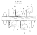
- FIG 1 is a longitudinal side view of the ice-cube feeding screw 33 according to the first embodiment of the present invention and FIG 2 is an enlarged sectional view of the fin 45 of the ice-cube feeding screw 33.
- the outer circumferential end portion 48 of the fin 45 in the radial direction is somewhat tilted toward the ice releasing section 24 with respect to the proximal portion 47 (portion coupled to the rotary shaft 34) of said fin 45.
- said fin 45 is spirally mounted at predetermined pitches on the outer circumference of the rotary shaft 34, while the entire abutting face 49 of the fin 45 directed toward the ice releasing section 24 is being tilted at a predetermined angle as it goes outward in the radial direction.
- the abutting face 49 of the fin 45 is tilted toward the ice releasing section 24, so that the outer circumferential end portion 48 of the fin 45 becomes to extend to the upper side of the ice cube S facing the gap 36, as shown in FIG. 1.
- the displacement in the external radial direction is appropriately regulated when the ice cubes S are moved toward the ice releasing section 24 by rotation of the ice-cube feeding screw 33.
- the ice cubes S are properly prevented from being moved out of the screw 33.
- the ice cubes S facing the gaps 36 of the fin 45 are reliably conveyed to the ice releasing port 23 of the ice releasing section 24 without being moved outward from the fin 45.
- the efficient conveyance of the ice cubes S and the stabilization of the release of the ice cubes S can be achieved.
- FIG 3 is a longitudinal side view of the ice-cube feeding screw 33 according to the second embodiment of the present invention and FIG 4 is an enlarged sectional view of the fin 51 of the ice-cube feeding screw 33.
- a portion of the fin 51 from its predetermined portion in the radial direction to the outer circumferential end portion 53 of the fin 51 is curved so that it tilts in the form of a curved surface toward the ice releasing section 24 as it goes outward in the radial direction.
- the abutting face 54 of the fin 51 directed to the ice releasing section 24, basically consists of a first abutting face 54a extending from the proximal portion 52 to a radial predetermined portion in a direction perpendicular to the rotary shaft 34 and a second abutting face 54b curved in the form of a curved surface at that predetermined portion toward the ice releasing section 24.
- Said fin 51 is wound at required pitches and firmly mounted on the outer circumference of the rotary shaft 34.
- the second abutting face 54b of the fin 51 is curved toward the ice releasing section 24, so that the outer circumferential end portion 53 of the fin 51 extends to the upper side of the ice cube S facing the gap 36, as shown in FIG. 3.
- the radially outward displacement thereof is appropriately regulated by the second abutting face 54b when the ice cubes S are moved toward the ice releasing section 24 by rotation of the ice-cube feeding screw 33.
- the ice cubes S are properly prevented from being moved outward from the screw 33.
- the ice cubes S facing the gaps 36 of the fin 51 are reliably conveyed to the ice releasing port 23 of the ice releasing section 24 without being moved outward from the fin 51. Therefore, the efficient conveyance of the ice cubes S and the stabilization of the release of the ice cubes S can be achieved.
- FIG. 5 is a longitudinal side view of the ice-cube feeding screw 33 according to the third embodiment of the present invention
- FIG. 6 is an enlarged sectional view of the fin 51 of the ice-cube feeding screw 33.
- a portion of the fin 61 from its predetermined portion in the radial direction to the outer circumferential end portion 63 of the fin 61 is bent so that it tilts linearly toward the ice releasing section 24 as it goes outward in the radial direction.
- the abutting face 64 of the fin 61 directed to the ice releasing section 24, basically consists of a first abutting face 64a extending from the proximal portion 62 to a radial predetermined portion in a direction perpendicular to the rotary shaft 34 and a second abutting face 64b tilted at that predetermined portion facing the outer circumferential end portion 63 toward the ice releasing section 24.
- the fin 61 is wound at required pitches and firmly mounted on the outer circumference of the rotary shaft 34.
- the second abutting face 64b of the fin 61 is tilted toward the ice releasing section 24, so that the outer circumferential end portion 63 of the fin 61 extends to the upper side of the ice cube S facing the gap 36, as shown in FIG. 5.
- the radially outward displacement thereof is appropriately regulated by the second abutting face 64b when the ice cubes S are moved toward the ice releasing section 24 by rotation of the ice-cube feeding screw 33.
- the ice cubes S are properly prevented from being moved outward from the screw 33.
- the ice cubes S facing the gaps 36 of the fins 61 are reliably conveyed to the ice releasing port 23 of the ice releasing section 24 without being moved outward from the fin 61. Therefore, the efficient conveyance of the ice cubes S and the stabilization of the release of the ice cubes S can be achieved.
- the present invention is not to be limited to that machine, but is suitably applicable to various types of ice making machines and ice stock bins.
- the entire abutting face of the fin in the ice-cube feeding screw tilts toward the ice releasing section. Therefore, when ice cubes facing the gaps of the fin are moved toward the ice releasing section by rotation of the ice-cube feeding screw, the radially outward movement of the ice cubes can be suitably regulated. As a result, since the ice cubes facing the gaps can be prevented from being displaced outward of the ice-cube feeding screw, the efficient conveyance of ice cubes and the stabilization of the release of ice cubes can be achieved.
- the second abutting face on the side of the outer circumferential end of the fin in the ice-cube feeding screw tilts toward the ice releasing section. Therefore, when ice cubes facing the gaps of the fin are moved toward the ice releasing section by rotation of the ice-cube feeding screw, the radially outward movement of the ice cubes can be suitably regulated. As a result, since the ice cubes facing the gaps can be prevented from being displaced outward of the ice-cube feeding screw, the efficient conveyance of ice cubes and the stabilization of the release of ice cubes can be achieved.
Landscapes
- Engineering & Computer Science (AREA)
- Physics & Mathematics (AREA)
- Mechanical Engineering (AREA)
- Thermal Sciences (AREA)
- General Engineering & Computer Science (AREA)
- Filling Or Emptying Of Bunkers, Hoppers, And Tanks (AREA)
- Devices That Are Associated With Refrigeration Equipment (AREA)
- Production, Working, Storing, Or Distribution Of Ice (AREA)
Applications Claiming Priority (2)
| Application Number | Priority Date | Filing Date | Title |
|---|---|---|---|
| JP5594598 | 1998-02-19 | ||
| JP10055945A JPH11237153A (ja) | 1998-02-19 | 1998-02-19 | 氷塊放出装置 |
Publications (2)
| Publication Number | Publication Date |
|---|---|
| EP0937954A1 true EP0937954A1 (fr) | 1999-08-25 |
| EP0937954B1 EP0937954B1 (fr) | 2001-02-28 |
Family
ID=13013226
Family Applications (1)
| Application Number | Title | Priority Date | Filing Date |
|---|---|---|---|
| EP99103316A Expired - Lifetime EP0937954B1 (fr) | 1998-02-19 | 1999-02-19 | Appareil de distribution de glaçons |
Country Status (3)
| Country | Link |
|---|---|
| EP (1) | EP0937954B1 (fr) |
| JP (1) | JPH11237153A (fr) |
| DE (1) | DE69900056T2 (fr) |
Cited By (4)
| Publication number | Priority date | Publication date | Assignee | Title |
|---|---|---|---|---|
| AU2007298047B2 (en) * | 2006-09-20 | 2010-06-17 | Lg Electronics Inc. | Refrigerator, ice bank and joint of the ice bank |
| CN113184466A (zh) * | 2021-04-13 | 2021-07-30 | 上海和科设备制造有限公司 | 翅片传送结构 |
| CN115535651A (zh) * | 2022-10-19 | 2022-12-30 | 合肥华凌股份有限公司 | 传动组件、制冰设备和冰箱 |
| CN119856862A (zh) * | 2025-02-21 | 2025-04-22 | 宁波爱科特生活电器有限公司 | 一种制冰饮水机 |
Families Citing this family (1)
| Publication number | Priority date | Publication date | Assignee | Title |
|---|---|---|---|---|
| JP4726344B2 (ja) * | 2001-07-05 | 2011-07-20 | ホシザキ電機株式会社 | 貯氷庫における氷搬出装置 |
Citations (3)
| Publication number | Priority date | Publication date | Assignee | Title |
|---|---|---|---|---|
| US3719307A (en) * | 1970-10-06 | 1973-03-06 | Mcquay Inc | Ice dispensing device |
| JPS6160511A (ja) * | 1984-08-30 | 1986-03-28 | Ube Ind Ltd | スクリユ−コンベヤ |
| EP0779483A1 (fr) * | 1995-12-15 | 1997-06-18 | CASTEL MAC S.p.A. | Appareil de distribution de glaçons |
-
1998
- 1998-02-19 JP JP10055945A patent/JPH11237153A/ja active Pending
-
1999
- 1999-02-19 EP EP99103316A patent/EP0937954B1/fr not_active Expired - Lifetime
- 1999-02-19 DE DE69900056T patent/DE69900056T2/de not_active Expired - Fee Related
Patent Citations (3)
| Publication number | Priority date | Publication date | Assignee | Title |
|---|---|---|---|---|
| US3719307A (en) * | 1970-10-06 | 1973-03-06 | Mcquay Inc | Ice dispensing device |
| JPS6160511A (ja) * | 1984-08-30 | 1986-03-28 | Ube Ind Ltd | スクリユ−コンベヤ |
| EP0779483A1 (fr) * | 1995-12-15 | 1997-06-18 | CASTEL MAC S.p.A. | Appareil de distribution de glaçons |
Cited By (4)
| Publication number | Priority date | Publication date | Assignee | Title |
|---|---|---|---|---|
| AU2007298047B2 (en) * | 2006-09-20 | 2010-06-17 | Lg Electronics Inc. | Refrigerator, ice bank and joint of the ice bank |
| CN113184466A (zh) * | 2021-04-13 | 2021-07-30 | 上海和科设备制造有限公司 | 翅片传送结构 |
| CN115535651A (zh) * | 2022-10-19 | 2022-12-30 | 合肥华凌股份有限公司 | 传动组件、制冰设备和冰箱 |
| CN119856862A (zh) * | 2025-02-21 | 2025-04-22 | 宁波爱科特生活电器有限公司 | 一种制冰饮水机 |
Also Published As
| Publication number | Publication date |
|---|---|
| DE69900056T2 (de) | 2001-07-19 |
| DE69900056D1 (de) | 2001-04-05 |
| EP0937954B1 (fr) | 2001-02-28 |
| JPH11237153A (ja) | 1999-08-31 |
Similar Documents
| Publication | Publication Date | Title |
|---|---|---|
| US5050777A (en) | Ice dispenser conveying apparatus having a rotating blade auger that operates in connection with a baffle opening to prevent wedging of ice bodies therebetween | |
| US8011202B2 (en) | Auger in ice bin and refrigerating machine having the same | |
| EP3786549B1 (fr) | Boîte de stockage de glace et réfrigérateur le comprenant | |
| US5273219A (en) | Ice dispenser | |
| EP3176523B1 (fr) | Réfrigérateur | |
| US7395672B2 (en) | Ice dispenser assembly and method of assembling same | |
| US20090145157A1 (en) | Ice dispensing technology | |
| EP3232141A1 (fr) | Bac à glace et réfrigérateur pourvu du bac à glace | |
| EP1722178A2 (fr) | Distributeur de glace et réfrigérateur contenant une telle distributeur | |
| EP0937954B1 (fr) | Appareil de distribution de glaçons | |
| CN1873353A (zh) | 电冰箱 | |
| EP0851192A2 (fr) | Machine de fabrication de glace du type à vis sans fin | |
| KR200191367Y1 (ko) | 냉장고용 얼음 이송장치 | |
| JP2006118770A (ja) | アイスディスペンサ | |
| CN1755308A (zh) | 电冰箱 | |
| CN100337078C (zh) | 电冰箱 | |
| KR100540792B1 (ko) | 오거 조립체 | |
| JP4401793B2 (ja) | 氷塊搬出装置 | |
| KR101291204B1 (ko) | 냉장고 | |
| CN223111487U (zh) | 一种防出料口凝冰的出冰结构和冷饮机 | |
| KR100417578B1 (ko) | 제빙기의 얼음 교반장치 | |
| JP2002031445A (ja) | 氷塊放出装置 | |
| JP5511543B2 (ja) | 氷搬送装置 | |
| KR20050082827A (ko) | 얼음 분쇄 및 마쇄기용 공급장치 | |
| JPH11257812A (ja) | 氷塊放出装置 |
Legal Events
| Date | Code | Title | Description |
|---|---|---|---|
| PUAI | Public reference made under article 153(3) epc to a published international application that has entered the european phase |
Free format text: ORIGINAL CODE: 0009012 |
|
| AK | Designated contracting states |
Kind code of ref document: A1 Designated state(s): DE ES FR GB IT NL |
|
| AX | Request for extension of the european patent |
Free format text: AL;LT;LV;MK;RO;SI |
|
| 17P | Request for examination filed |
Effective date: 19990902 |
|
| 17Q | First examination report despatched |
Effective date: 19991110 |
|
| AKX | Designation fees paid |
Free format text: DE ES FR GB IT NL |
|
| GRAG | Despatch of communication of intention to grant |
Free format text: ORIGINAL CODE: EPIDOS AGRA |
|
| GRAG | Despatch of communication of intention to grant |
Free format text: ORIGINAL CODE: EPIDOS AGRA |
|
| GRAH | Despatch of communication of intention to grant a patent |
Free format text: ORIGINAL CODE: EPIDOS IGRA |
|
| GRAH | Despatch of communication of intention to grant a patent |
Free format text: ORIGINAL CODE: EPIDOS IGRA |
|
| GRAA | (expected) grant |
Free format text: ORIGINAL CODE: 0009210 |
|
| AK | Designated contracting states |
Kind code of ref document: B1 Designated state(s): DE ES FR GB IT NL |
|
| ITF | It: translation for a ep patent filed | ||
| ET | Fr: translation filed | ||
| REF | Corresponds to: |
Ref document number: 69900056 Country of ref document: DE Date of ref document: 20010405 |
|
| PG25 | Lapsed in a contracting state [announced via postgrant information from national office to epo] |
Ref country code: ES Free format text: LAPSE BECAUSE OF FAILURE TO SUBMIT A TRANSLATION OF THE DESCRIPTION OR TO PAY THE FEE WITHIN THE PRESCRIBED TIME-LIMIT Effective date: 20010829 |
|
| REG | Reference to a national code |
Ref country code: GB Ref legal event code: IF02 |
|
| PLBE | No opposition filed within time limit |
Free format text: ORIGINAL CODE: 0009261 |
|
| STAA | Information on the status of an ep patent application or granted ep patent |
Free format text: STATUS: NO OPPOSITION FILED WITHIN TIME LIMIT |
|
| 26N | No opposition filed | ||
| PGFP | Annual fee paid to national office [announced via postgrant information from national office to epo] |
Ref country code: FR Payment date: 20020221 Year of fee payment: 4 |
|
| PGFP | Annual fee paid to national office [announced via postgrant information from national office to epo] |
Ref country code: DE Payment date: 20020304 Year of fee payment: 4 |
|
| PG25 | Lapsed in a contracting state [announced via postgrant information from national office to epo] |
Ref country code: GB Free format text: LAPSE BECAUSE OF NON-PAYMENT OF DUE FEES Effective date: 20030219 |
|
| PG25 | Lapsed in a contracting state [announced via postgrant information from national office to epo] |
Ref country code: NL Free format text: LAPSE BECAUSE OF NON-PAYMENT OF DUE FEES Effective date: 20030901 |
|
| PG25 | Lapsed in a contracting state [announced via postgrant information from national office to epo] |
Ref country code: DE Free format text: LAPSE BECAUSE OF NON-PAYMENT OF DUE FEES Effective date: 20030902 |
|
| GBPC | Gb: european patent ceased through non-payment of renewal fee | ||
| PG25 | Lapsed in a contracting state [announced via postgrant information from national office to epo] |
Ref country code: FR Free format text: LAPSE BECAUSE OF NON-PAYMENT OF DUE FEES Effective date: 20031031 |
|
| NLV4 | Nl: lapsed or anulled due to non-payment of the annual fee |
Effective date: 20030901 |
|
| REG | Reference to a national code |
Ref country code: FR Ref legal event code: ST |
|
| PG25 | Lapsed in a contracting state [announced via postgrant information from national office to epo] |
Ref country code: IT Free format text: LAPSE BECAUSE OF NON-PAYMENT OF DUE FEES Effective date: 20050219 |