EP0937961A2 - Positioniermechanismus - Google Patents
Positioniermechanismus Download PDFInfo
- Publication number
- EP0937961A2 EP0937961A2 EP99301102A EP99301102A EP0937961A2 EP 0937961 A2 EP0937961 A2 EP 0937961A2 EP 99301102 A EP99301102 A EP 99301102A EP 99301102 A EP99301102 A EP 99301102A EP 0937961 A2 EP0937961 A2 EP 0937961A2
- Authority
- EP
- European Patent Office
- Prior art keywords
- linkages
- axis
- axes
- plate
- movable part
- Prior art date
- Legal status (The legal status is an assumption and is not a legal conclusion. Google has not performed a legal analysis and makes no representation as to the accuracy of the status listed.)
- Granted
Links
Images



Classifications
-
- G—PHYSICS
- G12—INSTRUMENT DETAILS
- G12B—CONSTRUCTIONAL DETAILS OF INSTRUMENTS, OR COMPARABLE DETAILS OF OTHER APPARATUS, NOT OTHERWISE PROVIDED FOR
- G12B5/00—Adjusting position or attitude, e.g. level, of instruments or other apparatus, or of parts thereof; Compensating for the effects of tilting or acceleration, e.g. for optical apparatus
-
- G—PHYSICS
- G01—MEASURING; TESTING
- G01B—MEASURING LENGTH, THICKNESS OR SIMILAR LINEAR DIMENSIONS; MEASURING ANGLES; MEASURING AREAS; MEASURING IRREGULARITIES OF SURFACES OR CONTOURS
- G01B3/00—Measuring instruments characterised by the use of mechanical techniques
- G01B3/002—Details
-
- G—PHYSICS
- G02—OPTICS
- G02B—OPTICAL ELEMENTS, SYSTEMS OR APPARATUS
- G02B7/00—Mountings, adjusting means, or light-tight connections, for optical elements
- G02B7/003—Alignment of optical elements
- G02B7/004—Manual alignment, e.g. micromanipulators
Definitions
- This invention relates to a mechanism for a positioner and to a positioner having such a mechanism, more especially to a multi-axis positioning mechanism.
- One application for example, is the positioning of optical fibres relative to each other, relative to waveguides, laser diodes, detectors etc, prior to testing and joining.
- This type of positioning has to be very precise, typically of sub-micron precision, and is commonplace in research and production facilities in the telecommunications industry.
- Another application is for positioning optical or non-optical components, such as mirrors, lenses or samples beneath microscopes.
- multi-axis positioners are supplied as integrated units.
- the top plate of the x-stage can also serve as the base plate of the y-stage, to reduce size and weight.
- Flexure stages can also be nested in various ways to make them more compact.
- a mechanism for a multi-axis flexure positioner including a fixed part and a movable part, the movable part being connected to the fixed part via a plurality of transmission means, one for each axis, for transmitting actuation forces for the respective axes to the movable part, the transmission means for each axis including a flexure member arranged to transmit actuation forces for that axis to the movable part and to flex between the fixed part and the movable part in response to actuation forces associated with the or each other axis, wherein there are three flexure members arranged to extend along three mutually-perpendicular axes so that each flexure member is flexible along the axes of extent of the other two flexure members, each of the three flexure members comprising a pair of flexure linkages arranged to extend parallel to each other, the three pairs of linkages thus defining three mutually-perpendicular planes.
- Preferred embodiments of the invention incorporate up to six axes of motion into a positioning mechanism of this kind.
- the positioning mechanism forms a multi-axis positioner, preferably a micropositioner, with a corresponding number of axes of motion.
- the movable block of the positioner is supported by six linkages, each linkage being thinned towards each end to give the linkage flexibility to bend in two directions and to twist about its axis of extent.
- the new design allows multi-axis positioners to be made which have one or more of the following advantages:
- a sub-micron positioning precision is achievable.
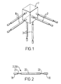
- Fig. 1 is to illustrate the principles of operation of the positioning mechanisms of embodiments of the invention.
- a movable block 7 is shown supported in space by three pairs of linkages 8, 2 and 3 via which the block 7 is moved in use.
- the three pairs of linkages are arranged to extend along mutually orthogonal axes x, y and z respectively.
- the ones of each pair of linkages extend parallel to each other, so that each pair of linkages lies in a plane, this plane being perpendicular to the equivalent two planes in which the other two pairs of linkages lie.
- each linkage needs to be rigid in respect of forces applied along an axis of extent of the linkage, referred to as lengthways in the following, but deformable in respect of forces applied across that axis of extent, referred to as sideways in the following. Consequently, a force applied to one end portion of the linkage substantially lengthways will be transmitted to the other end portion of the linkage, whereas a force applied to one end portion of the linkage sideways will not be transmitted to the other end of the linkage, but rather accommodated by lateral deformation of the linkage. That is, the linkage has a relatively high stiffness along its extent combined with a relatively low shear stiffness in respect of shear across its extent in at least one, but preferably all, lateral directions. It is also preferable that the torsional stiffness be relatively low in embodiments, such as the second embodiment, where rotary motions are possible.
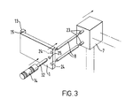
- the linkage shown in Fig. 2 is the design chosen to provide the desired lengthways rigidity and lateral and torsional deformability in the embodiments of the invention.
- the linkage comprises two end portions 18 and 19 disposed on either side of a central portion 20, the central and end portions being interconnected by two flexible portions 21 and 22.
- the central and end portions 18 to 20 are made of sections of stainless steel rod of 3mm diameter.
- the central portion is around 25mm in length and the end portions 10mm.
- the flexible portions 21 and 22 are made of sections of music wire of lmm diameter and are each around 15mm in free length with around 10mm at each end received in bores in the central and end portions and cemented in place by adhesive bonding, thus to leave a free length of the wire sections of around 10mm.
- Music wire is chosen since it allows a large degree of elastic bending and torsion without reaching the plastic limit.
- Other spring steel elements, or other suitable elements with similar properties, could also be used.
- the linkages 2, 3 and 8 are arranged with their end portions 19 located in the movable block 7 and their end portions 18 arranged to receive respective actuation forces from respective actuators (not shown in Fig. 1), for example micrometers.
- both of the linkages 8 are displaced together equal distances, the block 7 will be translated in a horizontal direction.
- the ends of the other linkages 2 and 3 remote from the block 7 are held fixed so that these linkages are subject to shear strain, as viewed along their respective axes of extent, which is accommodated by flexure of the flexible portions of the linkages.
- the set position can thus be varied in use by adjusting the position of the end portions 18 of the linkages arranged remote from the block. For a given pair of linkages, movement of the end portions 18 through equal distances will produce translation of the movable block 7, as in the above-described example, and movement of the end portions 18 through different amounts will produce rotation of the block 7.
- movable block 7 is illustrated as having the shape of a cube. This shape is chosen purely for ease of explanation. In reality, a cubic shape will not generally be the optimum shape, as will be appreciated further below.
- the movable block 7 may be a rigid body of any convenient shape.
- end portions 18 are attached to plates (not shown in Fig. 1) the mounting of which depends on the axes of motion required.
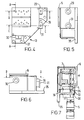
- Fig. 3 shows, highly schematically, the plate mounting arrangement adopted in the first embodiment of the invention, this arrangement being suitable for providing a linear movement of the block 7, by causing the ones of a pair of the linkages 8 to move together equal distances.
- Fig. 3 shows a plate 1 which is hingedly mounted relative to a case 13 via a hinge 15.
- the plate 1 need not literally have the form of a plate, but may be a rigid body of arbitrary shape arranged to rotate about a single axis in the manner of a hinge.
- the hinge axis is arranged to lie along a line parallel to a line drawn between the points where the linkages 8 meet the plate 1.
- the end portions 18 of the linkages 8 are located by locating means 24.
- the end portions 19 of the linkages are located by locating means 23 of the block 7).
- On the other side of the plate i.e.
- the actuator may be of any type, for example motorised fine thread or piezoelectric.
- a tension spring (not shown) holds the region 25 of the plate 1 in contact with the end of the micrometer spindle 32.
- the tension spring is connected at one end to the block 7 and extends through a through hole in the plate 1, being connected at its other end to a part of the case 13 located behind the plate 1.
- the micrometer 14 moves the plate 1, in turn moving the pair of linkages 8, causing the block 7 to move in an approximately straight line parallel to the linkages 8.
- the movement does in fact have small arcuate components as a result of the geometrical constraints imposed by the other pairs of linkages 2 and 3, which must bend to accommodate movement of the linkages 8. This effect is analogous to the motion of a conventional one-axis flexure stage.
- a three-axis positioner can be provided, allowing movement of the block 7 in three linear directions X, Y, & Z.
- motion is transmitted directly from the micrometer to the plate. It is however in some instances preferable for motion to be transmitted to the plate from the micrometer indirectly, such as by means of an intermediate crank or linkage.
- An example of an indirect drive of this kind is described further below for the z-transmission of the first and second embodiments.
- the x- and y-transmissions in these embodiments are direct.
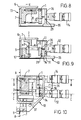
- a three-axis positioner is shown in Figs. 4 to 10 and will now be described.
- the movable part of the positioner is made of two parts which are bolted together, namely block 7 and platform 6 which serves as a top plate on which the optical fibre, lens or whatever can conveniently be mounted. Because these parts are bolted together, they behave as one rigid body.
- the six flexible linkages are arranged in three pairs, namely flexible x-linkages 8, flexible y-linkages 2 and flexible z-linkages 3. It can be seen that the three pairs lie in mutually perpendicular planes.
- One end of each linkage is attached to the block 7.
- the other ends of the respective pairs of linkages are attached to respective ones of the hinged plates, namely hinged x-plate 1, hinged y-plate 4 and hinged z-plate 9.
- the x-plate 1 moves about its hinge.
- the ends of the flexible x-linkages 8 attached to the plate 1 move through equal distances in the same direction as the micrometer axis, causing the movable part of the positioner 6 and 7 to move in the same direction also.
- the flexibility of the y- and z-linkages 2 & 3 allows this movement to occur over a range of travel which is a relatively small proportion of the linkage lengths.
- the travel in this example is limited to 4 mm on each axis. This relatively small range of travel is a common feature of all flexure stages.
- the operation of the Y axis is similar to that of the X axis.
- the operation of the Z (vertical) axis differs in that the motion is effectively cranked round by 90 degrees, so that the z-micrometer 12 can be mounted horizontally and not vertically. Additional parts, namely a hinged driver plate 11, on which bears the spindle 34 of the horizontally mounted z-micrometer 12, and a horizontally extending ball-ended linkage 10, interconnecting the driver plate 11 and the z-plate 9, are used to transmit the z-motion.
- the z-micrometer 12 can thus be positioned conveniently in terms of the detailed design.
- the z-micrometer could act directly on the hinged z-plate 9, similar to the X-and Y-micrometers, but in general this will be less convenient if the positioner is to be table mounted.
- Fig. 11 shows, highly schematically, the plate mounting arrangement adopted in the second embodiment of the invention, this arrangement being suitable for providing linear and rotary movement of the block 7.
- This is achieved by providing an arrangement in which two actuators 14 and 114, shown as micrometers, act on a pivotally mounted plate 1.
- the plate 1 is pivoted about a point B.
- the first micrometer 14 serves to impart a linear motion to the movable block 7. It acts at a point L such that a line LB, defined by points L and B, is perpendicular to the plane in which the two linkages 8 lie.
- the second micrometer 114 serves to impart a rotary motion to the movable block 7.
- a compression spring (not shown) holds the plate 1 in contact with the ends of the spindles of the micrometers 14 and 114.
- a bolt (not shown) is bolted into a part of the case 13 with the shank of the bolt passing through a through hole in the plate 1.
- the compression spring is helical and arranged over the shank of the bolt bearing at one end on the plate 1 in a region surrounding the rim of the through hole and at the other end on the head of the bolt, preferably via a washer.
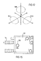
- a six-axis positioner can be provided, allowing movement of the block 7 in three linear directions X, Y, & Z and three rotary directions, YAW, ROLL & PITCH. Moreover, by correct dimensioning of the linkages it is possible to arrange for the three rotary motions of the movable block 7, associated with the three respective plates, to occur around axes that intersect at a common point P, as is the case in the concrete example of the second embodiment described further below.
- the pivot plate can be substituted with a hinged plate hinged about the line LB and the actuator 14 dispensed with.
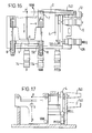
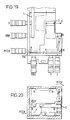
- FIG. 13 to 20 A practical example of a six-axis positioner according to the second embodiment is shown in Figs. 13 to 20 and will now be described, also with reference to Fig. 12.
- the movable part of the positioner is made of two parts 6 and 7 for ease of manufacture.
- the moving plates are mounted pivotally at a point B allowing pivoting in two directions.
- One micrometer 14, for x-actuation tilts the plate about an axis parallel to the plane of the linkages. This moves the linkages through the same distance, causing the block 7 and platform 6 to translate.
- the other micrometer 114, for yaw-actuation tilts the plate about an axis perpendicular to the plane of the linkages. This moves the linkages through different distances, in this example equal but opposite distances, causing the block 7 and platform 6 to rotate about the point P.
- Operation of the movable Y-plate 4 is similar to the movable X-plate.
- the movable Z-plate 9 differs in that motion is transmitted to it via additional parts, namely two lever blocks, a ball-ended linkage and a lever plate. The result is essentially the same as if the micrometers acted directly on the plate, however the additional parts allow the micrometers to be mounted horizontally in convenient positions.
Landscapes
- Physics & Mathematics (AREA)
- General Physics & Mathematics (AREA)
- Optics & Photonics (AREA)
- Details Of Measuring And Other Instruments (AREA)
- Vehicle Body Suspensions (AREA)
- Body Structure For Vehicles (AREA)
- Mechanical Control Devices (AREA)
- Transmission Devices (AREA)
- Wire Bonding (AREA)
- Eye Examination Apparatus (AREA)
- Die Bonding (AREA)
Applications Claiming Priority (2)
| Application Number | Priority Date | Filing Date | Title |
|---|---|---|---|
| GB9803716 | 1998-02-20 | ||
| GB9803716A GB2334593B (en) | 1998-02-20 | 1998-02-20 | Positioning mechanism |
Publications (3)
| Publication Number | Publication Date |
|---|---|
| EP0937961A2 true EP0937961A2 (de) | 1999-08-25 |
| EP0937961A3 EP0937961A3 (de) | 2001-05-23 |
| EP0937961B1 EP0937961B1 (de) | 2005-04-13 |
Family
ID=10827395
Family Applications (1)
| Application Number | Title | Priority Date | Filing Date |
|---|---|---|---|
| EP99301102A Expired - Lifetime EP0937961B1 (de) | 1998-02-20 | 1999-02-16 | Positioniermechanismus |
Country Status (5)
| Country | Link |
|---|---|
| US (2) | US6193226B1 (de) |
| EP (1) | EP0937961B1 (de) |
| AT (1) | ATE293242T1 (de) |
| DE (1) | DE69924659T2 (de) |
| GB (1) | GB2334593B (de) |
Cited By (9)
| Publication number | Priority date | Publication date | Assignee | Title |
|---|---|---|---|---|
| EP1113191A2 (de) | 1999-12-22 | 2001-07-04 | Agie Sa | Bewegungsübertragungsvorrichtung |
| WO2002055201A3 (en) * | 2001-01-12 | 2002-11-14 | Scientific Generics Limited | Sample processing apparatus |
| EP1402992A1 (de) | 2002-09-27 | 2004-03-31 | Sysmelec SA | Vorrichtung mit höher Präzision zum Vorgeben oder zum Messen einer Position oder Kraft |
| WO2004068022A3 (en) * | 2003-01-28 | 2004-12-16 | Melles Griot Ltd | Multi-axis positioner |
| WO2006045264A1 (de) * | 2004-10-29 | 2006-05-04 | Leica Microsystems Cms Gmbh | Vorrichtung zur justage einer optischen faser oder eines optischen faserbündels |
| DE10004661B4 (de) * | 2000-02-03 | 2008-10-16 | Leica Microsystems Cms Gmbh | Vorrichtung zum Schwenken eines Lichtstrahls |
| US7652409B2 (en) | 2004-02-20 | 2010-01-26 | Thorlabs, Inc. | Positioner device |
| CN108088342A (zh) * | 2017-12-21 | 2018-05-29 | 北京理工大学 | 一种微小型定位调距装置 |
| EP4425783A1 (de) * | 2023-03-03 | 2024-09-04 | Thorlabs Inc. | Mehrachsige nanopositionier-biegebühne mit grob- und feinanpassung |
Families Citing this family (16)
| Publication number | Priority date | Publication date | Assignee | Title |
|---|---|---|---|---|
| US6712154B2 (en) | 1998-11-16 | 2004-03-30 | Enventure Global Technology | Isolation of subterranean zones |
| US6606444B2 (en) | 2000-09-28 | 2003-08-12 | Murray R. Harman | Positioning device especially for assembling optical components |
| US6688183B2 (en) | 2001-01-19 | 2004-02-10 | Massachusetts Institute Of Technology | Apparatus having motion with pre-determined degrees of freedom |
| US6480651B1 (en) | 2001-07-13 | 2002-11-12 | Jds Uniphase Inc. | Method and apparatus for aligning optical components |
| US7068891B1 (en) * | 2002-03-12 | 2006-06-27 | Palomar Technologies, Inc. | System and method for positioning optical fibers |
| WO2006098010A1 (ja) * | 2005-03-16 | 2006-09-21 | Hirata Corporation | 精密位置決め装置 |
| CN100483564C (zh) * | 2005-09-22 | 2009-04-29 | 同方威视技术股份有限公司 | 一种用于调整x射线束流的准直器 |
| US8116017B2 (en) * | 2006-03-14 | 2012-02-14 | Abet Technologies, Inc. | Reduced vibration optical system with inexpensive precision positioning assembly |
| EP2101964B1 (de) * | 2006-10-31 | 2012-07-04 | Force Dimension Technologies Sàrl | Parallele kinematische struktur |
| US8072120B2 (en) * | 2008-11-26 | 2011-12-06 | Shorya Awtar | Multiple degrees of freedom motion system |
| DE202010002684U1 (de) | 2010-02-23 | 2011-09-12 | Deutsche Mechatronics Gmbh | Mikropositionierer |
| CN102221734B (zh) * | 2011-06-14 | 2012-11-07 | 中南大学 | 一种光电子器件封装对准的单自由度微动平台 |
| CN104777581B (zh) * | 2015-04-21 | 2017-03-01 | 中国科学院长春光学精密机械与物理研究所 | 一种结构紧凑的空间相机装调用三维调整装置 |
| DE102017107282B4 (de) | 2017-04-05 | 2021-02-25 | Precitec Gmbh & Co. Kg | Kartesische Positioniervorrichtung und Laserbearbeitungskopf mit derselben |
| CN109465652B (zh) * | 2018-11-30 | 2023-09-22 | 广东工业大学 | 接触式刚度切换装置及使用其的刚柔耦合运动平台和方法 |
| JP6727676B1 (ja) | 2019-09-09 | 2020-07-22 | マイスターバイオ株式会社 | ガン予防及び/又は治療用組成物 |
Family Cites Families (19)
| Publication number | Priority date | Publication date | Assignee | Title |
|---|---|---|---|---|
| CH263705A (fr) * | 1940-11-21 | 1949-09-15 | Monchablon Jacques | Micromanipulateur. |
| GB1252667A (de) * | 1969-01-17 | 1971-11-10 | ||
| DE2218156A1 (de) * | 1971-06-18 | 1972-12-21 | Bausch & Lomb | Objekttragerfinger fur Mikroskop |
| JPS5345865A (en) * | 1976-10-05 | 1978-04-25 | Nippon Telegr & Teleph Corp <Ntt> | Micromanipulator |
| SE420131B (sv) * | 1980-01-22 | 1981-09-14 | Leon Carlson | Anordning for forflyttning av ett bord i tva godtyckliga riktningar i ett och samma plan |
| US4523383A (en) * | 1982-07-28 | 1985-06-18 | Renishaw Electrical Limited | Position sensing apparatus |
| GB2129955B (en) * | 1982-11-02 | 1986-07-09 | Martock Design Ltd | Adjustable mountings |
| NL8402765A (nl) * | 1984-09-11 | 1986-04-01 | Philips Nv | Manipulator met zes vrijheidsgraden. |
| GB2185323B (en) * | 1984-10-12 | 1988-01-06 | Vickers Plc | Microscope having an improved stage |
| NL8500615A (nl) * | 1985-03-05 | 1986-10-01 | Nederlanden Staat | Fijninstelmechanisme voor het nauwkeurig positioneren van een instelelement. |
| CH672089A5 (de) | 1985-12-16 | 1989-10-31 | Sogeva Sa | |
| FR2606890B1 (fr) * | 1986-11-18 | 1989-06-30 | Lyonnaise Transmiss Optiques | Dispositif de deplacement de l'extremite d'une fibre optique suivant deux axes orthogonaux |
| DE3905952A1 (de) * | 1989-02-25 | 1990-08-30 | Kugelfischer G Schaefer & Co | Mehrkoordinatenmesstaster |
| US5140470A (en) * | 1991-01-07 | 1992-08-18 | New Focus, Inc. | Optical mounting apparatus |
| US5412503A (en) * | 1992-08-27 | 1995-05-02 | U.S. Philips Corporation | Specimen holder for a particle beam optical apparatus |
| US5357366A (en) * | 1992-12-08 | 1994-10-18 | Marchlenski Stanley P | Mechanical stage adjustment mechanism |
| JPH07218749A (ja) * | 1993-12-07 | 1995-08-18 | Furukawa Electric Co Ltd:The | 多軸微動ステージ |
| DE19742802C1 (de) * | 1997-09-27 | 1998-10-22 | Leica Mikroskopie & Syst | Mikroskopstativ für ein Waferinspektionsmikroskop |
| US6252705B1 (en) * | 1999-05-25 | 2001-06-26 | Schlumberger Technologies, Inc. | Stage for charged particle microscopy system |
-
1998
- 1998-02-20 GB GB9803716A patent/GB2334593B/en not_active Expired - Lifetime
-
1999
- 1999-02-16 EP EP99301102A patent/EP0937961B1/de not_active Expired - Lifetime
- 1999-02-16 AT AT99301102T patent/ATE293242T1/de not_active IP Right Cessation
- 1999-02-16 DE DE69924659T patent/DE69924659T2/de not_active Expired - Lifetime
- 1999-02-17 US US09/251,555 patent/US6193226B1/en not_active Expired - Lifetime
-
2000
- 2000-10-30 US US09/702,353 patent/US6467762B1/en not_active Expired - Lifetime
Cited By (14)
| Publication number | Priority date | Publication date | Assignee | Title |
|---|---|---|---|---|
| EP1113191A3 (de) * | 1999-12-22 | 2005-01-05 | Agie Sa | Bewegungsübertragungsvorrichtung |
| DE19962247A1 (de) * | 1999-12-22 | 2001-09-20 | Agie Sa | Bewegungsübertragungsvorrichtung |
| US6453566B1 (en) | 1999-12-22 | 2002-09-24 | Agie Sa | Movement transmission unit and movement transmission apparatus employing the same |
| EP1113191A2 (de) | 1999-12-22 | 2001-07-04 | Agie Sa | Bewegungsübertragungsvorrichtung |
| DE10004661B4 (de) * | 2000-02-03 | 2008-10-16 | Leica Microsystems Cms Gmbh | Vorrichtung zum Schwenken eines Lichtstrahls |
| WO2002055201A3 (en) * | 2001-01-12 | 2002-11-14 | Scientific Generics Limited | Sample processing apparatus |
| EP1402992A1 (de) | 2002-09-27 | 2004-03-31 | Sysmelec SA | Vorrichtung mit höher Präzision zum Vorgeben oder zum Messen einer Position oder Kraft |
| US6871548B2 (en) | 2002-09-27 | 2005-03-29 | Sysmelec Sa | High precision apparatus for imposing or measuring a position or a force |
| WO2004068022A3 (en) * | 2003-01-28 | 2004-12-16 | Melles Griot Ltd | Multi-axis positioner |
| US7652409B2 (en) | 2004-02-20 | 2010-01-26 | Thorlabs, Inc. | Positioner device |
| WO2006045264A1 (de) * | 2004-10-29 | 2006-05-04 | Leica Microsystems Cms Gmbh | Vorrichtung zur justage einer optischen faser oder eines optischen faserbündels |
| US7600926B2 (en) | 2004-10-29 | 2009-10-13 | Leica Microsystems Cms Gmbh | Device for adjusting an optical fiber or an optical fiber bundle |
| CN108088342A (zh) * | 2017-12-21 | 2018-05-29 | 北京理工大学 | 一种微小型定位调距装置 |
| EP4425783A1 (de) * | 2023-03-03 | 2024-09-04 | Thorlabs Inc. | Mehrachsige nanopositionier-biegebühne mit grob- und feinanpassung |
Also Published As
| Publication number | Publication date |
|---|---|
| US6467762B1 (en) | 2002-10-22 |
| US6193226B1 (en) | 2001-02-27 |
| DE69924659D1 (de) | 2005-05-19 |
| GB2334593B (en) | 2002-07-17 |
| GB9803716D0 (en) | 1998-04-15 |
| EP0937961B1 (de) | 2005-04-13 |
| EP0937961A3 (de) | 2001-05-23 |
| DE69924659T2 (de) | 2006-01-12 |
| ATE293242T1 (de) | 2005-04-15 |
| GB2334593A (en) | 1999-08-25 |
Similar Documents
| Publication | Publication Date | Title |
|---|---|---|
| EP0937961B1 (de) | Positioniermechanismus | |
| US6145405A (en) | Coordinate positioning machine | |
| Pernette et al. | Design of parallelrobots in microrobotics | |
| EP0674969B1 (de) | Koordinaten-Positionierungsmaschine | |
| US5986827A (en) | Precision tip-tilt-piston actuator that provides exact constraint | |
| EP1684950B1 (de) | Parallelkinematikmechanismus mit einem konzentrischen kugelgelenk | |
| US6606444B2 (en) | Positioning device especially for assembling optical components | |
| WO2006000352A1 (de) | Positioniereinheit und vorrichtung zur justage für ein optisches element | |
| JP2013047836A (ja) | 光学モジュール | |
| GB2411288A (en) | Positioner device | |
| JP2004529780A (ja) | 産業用ロボット | |
| JP2004506529A (ja) | 構成部材を多軸的に精密調整可能に支承するための装置 | |
| US7063300B2 (en) | Device for fixing and adjusting a member to be supported | |
| US6498892B1 (en) | Positioning device especially for assembling optical components | |
| KR102499992B1 (ko) | 지지 장치 | |
| US7284459B2 (en) | Remote center of rotation positioning device | |
| JPH06500867A (ja) | 位置決め装置 | |
| JP2001121460A (ja) | ロボット用パラレルリンク機構 | |
| US20030033703A1 (en) | Positioning stage | |
| JPH10186198A (ja) | 平行・真直微動装置およびこれを用いたレンズ鏡筒の微小移動装置 | |
| EP0177993A1 (de) | Handhabungsgerät mit sechs Freiheitsgraden | |
| JP2000326272A (ja) | ロボット装置 | |
| JP2000009867A (ja) | ステージ移動装置 | |
| US7249535B2 (en) | Two-dimensional displacement apparatus | |
| JP2773781B2 (ja) | 精密微動ステージ装置 |
Legal Events
| Date | Code | Title | Description |
|---|---|---|---|
| PUAI | Public reference made under article 153(3) epc to a published international application that has entered the european phase |
Free format text: ORIGINAL CODE: 0009012 |
|
| AK | Designated contracting states |
Kind code of ref document: A2 Designated state(s): AT BE CH DE DK ES FI FR GB GR IE IT LI NL PT SE Kind code of ref document: A2 Designated state(s): AT BE CH DE DK ES FI FR GR IE IT LI NL PT SE |
|
| AX | Request for extension of the european patent |
Free format text: AL;LT;LV;MK;RO;SI |
|
| PUAL | Search report despatched |
Free format text: ORIGINAL CODE: 0009013 |
|
| AK | Designated contracting states |
Kind code of ref document: A3 Designated state(s): AT BE CH CY DE DK ES FI FR GB GR IE IT LI LU MC NL PT SE |
|
| AX | Request for extension of the european patent |
Free format text: AL;LT;LV;MK;RO;SI |
|
| RIC1 | Information provided on ipc code assigned before grant |
Free format text: 7G 01B 5/00 A, 7B 23Q 1/36 B, 7G 02B 6/38 B |
|
| 17P | Request for examination filed |
Effective date: 20011107 |
|
| AKX | Designation fees paid |
Free format text: AT BE CH DE DK ES FI FR GB GR IE IT LI NL PT SE |
|
| 17Q | First examination report despatched |
Effective date: 20020215 |
|
| GRAH | Despatch of communication of intention to grant a patent |
Free format text: ORIGINAL CODE: EPIDOS IGRA |
|
| GRAH | Despatch of communication of intention to grant a patent |
Free format text: ORIGINAL CODE: EPIDOS IGRA |
|
| RBV | Designated contracting states (corrected) |
Designated state(s): AT BE CH DE DK ES FI FR GR IE IT LI NL PT SE |
|
| RAP1 | Party data changed (applicant data changed or rights of an application transferred) |
Owner name: THORLABS, INC. |
|
| GRAA | (expected) grant |
Free format text: ORIGINAL CODE: 0009210 |
|
| AK | Designated contracting states |
Kind code of ref document: B1 Designated state(s): AT BE CH DE DK ES FI FR GR IE IT LI NL PT SE |
|
| PG25 | Lapsed in a contracting state [announced via postgrant information from national office to epo] |
Ref country code: NL Free format text: LAPSE BECAUSE OF FAILURE TO SUBMIT A TRANSLATION OF THE DESCRIPTION OR TO PAY THE FEE WITHIN THE PRESCRIBED TIME-LIMIT Effective date: 20050413 Ref country code: LI Free format text: LAPSE BECAUSE OF FAILURE TO SUBMIT A TRANSLATION OF THE DESCRIPTION OR TO PAY THE FEE WITHIN THE PRESCRIBED TIME-LIMIT Effective date: 20050413 Ref country code: FI Free format text: LAPSE BECAUSE OF FAILURE TO SUBMIT A TRANSLATION OF THE DESCRIPTION OR TO PAY THE FEE WITHIN THE PRESCRIBED TIME-LIMIT Effective date: 20050413 Ref country code: CH Free format text: LAPSE BECAUSE OF FAILURE TO SUBMIT A TRANSLATION OF THE DESCRIPTION OR TO PAY THE FEE WITHIN THE PRESCRIBED TIME-LIMIT Effective date: 20050413 Ref country code: BE Free format text: LAPSE BECAUSE OF FAILURE TO SUBMIT A TRANSLATION OF THE DESCRIPTION OR TO PAY THE FEE WITHIN THE PRESCRIBED TIME-LIMIT Effective date: 20050413 Ref country code: AT Free format text: LAPSE BECAUSE OF FAILURE TO SUBMIT A TRANSLATION OF THE DESCRIPTION OR TO PAY THE FEE WITHIN THE PRESCRIBED TIME-LIMIT Effective date: 20050413 |
|
| REG | Reference to a national code |
Ref country code: CH Ref legal event code: EP |
|
| REG | Reference to a national code |
Ref country code: IE Ref legal event code: FG4D |
|
| REF | Corresponds to: |
Ref document number: 69924659 Country of ref document: DE Date of ref document: 20050519 Kind code of ref document: P |
|
| PG25 | Lapsed in a contracting state [announced via postgrant information from national office to epo] |
Ref country code: SE Free format text: LAPSE BECAUSE OF FAILURE TO SUBMIT A TRANSLATION OF THE DESCRIPTION OR TO PAY THE FEE WITHIN THE PRESCRIBED TIME-LIMIT Effective date: 20050713 Ref country code: GR Free format text: LAPSE BECAUSE OF FAILURE TO SUBMIT A TRANSLATION OF THE DESCRIPTION OR TO PAY THE FEE WITHIN THE PRESCRIBED TIME-LIMIT Effective date: 20050713 Ref country code: DK Free format text: LAPSE BECAUSE OF FAILURE TO SUBMIT A TRANSLATION OF THE DESCRIPTION OR TO PAY THE FEE WITHIN THE PRESCRIBED TIME-LIMIT Effective date: 20050713 |
|
| PG25 | Lapsed in a contracting state [announced via postgrant information from national office to epo] |
Ref country code: PT Free format text: LAPSE BECAUSE OF FAILURE TO SUBMIT A TRANSLATION OF THE DESCRIPTION OR TO PAY THE FEE WITHIN THE PRESCRIBED TIME-LIMIT Effective date: 20050913 |
|
| NLV1 | Nl: lapsed or annulled due to failure to fulfill the requirements of art. 29p and 29m of the patents act | ||
| REG | Reference to a national code |
Ref country code: CH Ref legal event code: PL |
|
| PG25 | Lapsed in a contracting state [announced via postgrant information from national office to epo] |
Ref country code: IE Free format text: LAPSE BECAUSE OF NON-PAYMENT OF DUE FEES Effective date: 20060216 |
|
| PLBE | No opposition filed within time limit |
Free format text: ORIGINAL CODE: 0009261 |
|
| STAA | Information on the status of an ep patent application or granted ep patent |
Free format text: STATUS: NO OPPOSITION FILED WITHIN TIME LIMIT |
|
| ET | Fr: translation filed | ||
| 26N | No opposition filed |
Effective date: 20060116 |
|
| REG | Reference to a national code |
Ref country code: IE Ref legal event code: MM4A |
|
| PG25 | Lapsed in a contracting state [announced via postgrant information from national office to epo] |
Ref country code: ES Free format text: LAPSE BECAUSE OF NON-PAYMENT OF DUE FEES Effective date: 20060228 |
|
| REG | Reference to a national code |
Ref country code: FR Ref legal event code: PLFP Year of fee payment: 18 |
|
| REG | Reference to a national code |
Ref country code: FR Ref legal event code: PLFP Year of fee payment: 19 |
|
| REG | Reference to a national code |
Ref country code: FR Ref legal event code: PLFP Year of fee payment: 20 |
|
| PGFP | Annual fee paid to national office [announced via postgrant information from national office to epo] |
Ref country code: DE Payment date: 20180227 Year of fee payment: 20 |
|
| PGFP | Annual fee paid to national office [announced via postgrant information from national office to epo] |
Ref country code: IT Payment date: 20180222 Year of fee payment: 20 Ref country code: FR Payment date: 20180227 Year of fee payment: 20 |
|
| REG | Reference to a national code |
Ref country code: DE Ref legal event code: R071 Ref document number: 69924659 Country of ref document: DE |