EP0938201A2 - Station de terminal radio pour réseau SDH et méthode pour en sélectionner une horloge de travail - Google Patents
Station de terminal radio pour réseau SDH et méthode pour en sélectionner une horloge de travail Download PDFInfo
- Publication number
- EP0938201A2 EP0938201A2 EP99103062A EP99103062A EP0938201A2 EP 0938201 A2 EP0938201 A2 EP 0938201A2 EP 99103062 A EP99103062 A EP 99103062A EP 99103062 A EP99103062 A EP 99103062A EP 0938201 A2 EP0938201 A2 EP 0938201A2
- Authority
- EP
- European Patent Office
- Prior art keywords
- clock
- quality
- quality information
- multiplexing
- priority
- Prior art date
- Legal status (The legal status is an assumption and is not a legal conclusion. Google has not performed a legal analysis and makes no representation as to the accuracy of the status listed.)
- Granted
Links
Images


Classifications
-
- H—ELECTRICITY
- H04—ELECTRIC COMMUNICATION TECHNIQUE
- H04J—MULTIPLEX COMMUNICATION
- H04J3/00—Time-division multiplex systems
- H04J3/02—Details
- H04J3/06—Synchronising arrangements
- H04J3/0635—Clock or time synchronisation in a network
- H04J3/0685—Clock or time synchronisation in a node; Intranode synchronisation
- H04J3/0688—Change of the master or reference, e.g. take-over or failure of the master
-
- H—ELECTRICITY
- H04—ELECTRIC COMMUNICATION TECHNIQUE
- H04J—MULTIPLEX COMMUNICATION
- H04J3/00—Time-division multiplex systems
- H04J3/02—Details
- H04J3/06—Synchronising arrangements
- H04J3/0635—Clock or time synchronisation in a network
- H04J3/0685—Clock or time synchronisation in a node; Intranode synchronisation
- H04J3/0691—Synchronisation in a TDM node
-
- H—ELECTRICITY
- H04—ELECTRIC COMMUNICATION TECHNIQUE
- H04J—MULTIPLEX COMMUNICATION
- H04J2203/00—Aspects of optical multiplex systems other than those covered by H04J14/05 and H04J14/07
- H04J2203/0001—Provisions for broadband connections in integrated services digital network using frames of the Optical Transport Network [OTN] or using synchronous transfer mode [STM], e.g. SONET, SDH
- H04J2203/0028—Local loop
- H04J2203/003—Medium of transmission, e.g. fibre, cable, radio
- H04J2203/0035—Radio
Definitions
- the present invention relates to a radio terminal station apparatus for an SDH network, particularly to a method of selecting an operation clock in a radio terminal station apparatus for an SDH communication connected to a wired transmission line or a wireless transmission line.
- SDH Serial Digital Hierarchy
- STM-1 Synchronous Digital Hierarchy
- SOH Section Over Head
- an S1 byte in the SOH is defined for transmitting a quality that is the quality of a clock in a synchronous network.
- the quality indicated by the S1 byte is defined by ITU-TG.707 or the like.
- a secondary clock source is provided for use when a trouble arises on this primary clock source and it can not be used, and the primary and secondary clock sources are switched over with the quality in the S1 byte.
- a clock source of a lower quality than the primary clock is mostly employed for an economical reason or the like.
- each NE (Network Element: synchronous terminal station apparatus) mostly has an internal clock source that is used when either of the primary and secondary clock sources can not be used.
- transmission terminal station apparatus that make communications through wired transmission lines such as optical cables and radio terminal station apparatus that are connected to such transmission terminal station apparatus and make communications through wireless transmission lines.
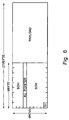
- Fig. 8 shows an example in which an SDH network is built with such transmission and radio terminal station apparatus.
- NE1, NE2, NE7 and NE10 denote transmission terminal station apparatus, and NE3, NE4, NE5, NE6, NE8 and NE9 do radio terminal station apparatus.
- U1 denotes a primary clock source that is the origin of an ordinary SDH synchronous network, and U2 does a secondary clock source.
- each of SYS1 and 2 has a set of up-link or down-link data signal sequences including SDH frames, and MUX denotes a multiplexer, and DMR does a digital microwave radio equipment.
- a wireless transmission line data signal sequences of plural system are transmitted and received through a single antenna in general, so the network never branches at the wireless line.
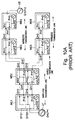
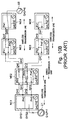
- a conventional radio or transmission terminal station apparatus has clock selection means in which a process of a flowchart shown in Fig. 9A or 9B is carried out as a method of determining a quality to insert.
- Fig. 9A shows a flowchart used when the transmission directions of the whole system are the same like radio terminal station apparatus.
- Q F on the qualities to multiplex on all systems in which the direction of multiplexing the qualities is opposite to the line clock that was the origin of the clock in the apparatus.
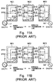
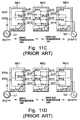
- Fig. 10A shows synchronization of clocks in a stationary state.
- line clocks of both routes of (NE1 ⁇ NE2 ⁇ NE3 ⁇ NE4) and (NE1 ⁇ NE2 ⁇ NE5 ⁇ NE6) all are synchronized with the output clock of U1.
- (NE1 ⁇ NE2) denotes direction of clock signal transmitted from NE1 to NE2.
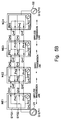
- Fig. 11A shows synchronization of clocks in a stationary state.
- the present invention has been made in view of the above points at issue and aims to provide a radio terminal station apparatus for an SDH network, wherein, by defining a special priority value in a system beforehand, a redundant construction for a route having a line clock of a high quality is maintained and the synchronous network construction never breaks even in case that a wired transmission line is branched, and a method of selecting an operation clock thereof.
- the quality/clock extracted from each system and each direction is input to a clock selection part.
- this clock selection part first, in a quality judgement circuit, the route information and quality value of the clock of the highest quality from among the qualities of an external clock, an internal clock and a line clock from each system are output to a control signal generation circuit.
- the control signal generation circuit in case of a single clock of the highest quality in the input quality information, the clock is selected, and, in case of a plurality of clocks, the route of the highest priority judged by a priority judgement circuit is selected, and a clock selection signal for using it as the clock in the apparatus, and the quality and extraction route information of the clock to be the clock in the apparatus are output.
- the direction and system to multiplex the quality are compared with the input direction and system of the clock in the apparatus, and, only in case of not the same system but the opposite direction and when the priority establishment of the input opposite to the insertion direction is a special value defined in advance, the same quality as the clock in the apparatus is multiplexed.
- a communication terminal station apparatus when determining a quality to multiplex, by using the priority established on the input opposite to the direction to multiplex the quality, a communication terminal station apparatus can be provided wherein, even in case of the transmission route of the data signal sequence branching, the synchronous network of the branched route never breaks, and further, in case that there are a plurality of routes having clocks of high qualities in the same direction, the degree of redundant can be kept and the synchronous network construction never breaks.
- Fig. 1 is a block diagram of an embodiment of the present invention.
- the embodiment shown in Fig. 1 is a radio terminal station apparatus having systems (SYS) each of which has a set of up-link and down-link data signal sequences including SDH frame constructions, for N (N is an integer of two or more) systems (SYS1 to N), wherein 101 to 10N and 211 to 21N denote data signal sequences connected to transmission terminal station apparatus or the like through wired transmission lines, and 111 to 11N and 201 to 20N do data signal sequences to transmit and receive through wireless transmission lines via a modem or the like.
- SYS systems
- N is an integer of two or more systems
- 101 to 10N and 211 to 21N denote data signal sequences connected to transmission terminal station apparatus or the like through wired transmission lines
- 111 to 11N and 201 to 20N do data signal sequences to transmit and receive through wireless transmission lines via a modem or the like.
- the data signal sequence 101 transmitted through the wired transmission line is input to a quality/clock extraction circuit 13-11, and the line clock 301 and quality information (quality) 401 of the line clock contained in SOH (Section Over Head) are extracted to be input to a line clock input circuit 1 of clock selection part 20 and a quality judgement circuit 7 in quality determination part 21.
- SOH Section Over Head
- the data signal sequence 201 through the wireless transmission line is input to a quality/clock extraction circuit 13-12, and the line clock 311 and quality 411 are output.
- the line clocks 30n and 31n synchronized with the wired and wireless transmission lines, respectively, and the respective qualities 40n and 41n are output to the above line clock input circuit 1 and quality judgement circuit 7.
- An external clock input circuit 2 is a circuit to which a clock of an external clock source to be a basis of the synchronous network in the SDH network is input, and M (M is a natural number) clocks 601 to 60M can be input.
- M is a natural number
- the apparatus for outputting the clock to be a basis of the synchronous network is mostly set up in the master and slave stations, and, in the other stations, there is no input of clock to the external clock input circuit 2.
- An internal clock generation circuit 3 is a circuit for generating a clock necessary to transmit a data signal sequence to a low-ranking station when any line clock can not be extracted due to a trouble or the like on a transmission line.
- Outputs of the external clock input circuit 2 and internal clock generation circuit 3 are input to a clock selection circuit 4.
- the clock selection circuit 4 determines a clock used in the apparatus on the basis of control information 91 from a control signal generation circuit 9 described later, and then outputs it to a clock-in-apparatus generation circuit 11.
- the clock-in-apparatus generation circuit 11 outputs a clock-in-apparatus 110 synchronized with an output clock of the clock selection circuit to a clock change circuit 14 of each system.
- a quality establishment part 5 is a circuit for establishing qualities for an input clock to the external clock input circuit 2 and a clock of the internal clock generation circuit 3, and establishes a quality of a route that no quality can be obtained from SOH and outputs it to a quality judgement circuit 7.
- a priority establishment part 6 is a circuit for establishing the degree of priority to the line clocks 301 to 30N, external clocks 601 to 60M and internal clock 300, namely, all clocks input to the clock selection circuit 4, and assigns numerical values in descending order of the degree of priority. Further, a special priority for changing processing methods in quality determination part 21 described later can be established. In the quality determination part 21, in the quality judgement circuit 7, the qualities of input clocks to the clock selection circuit 4 are judged and route information 71 of the clock of the best quality is output.
- a priority judgement circuit 8 detects a priority established to the input clock to the clock selection circuit 4 to output route establishment information 81, and, when there is a route that a special priority defined in advance has been established, outputs special priority route information 82.
- the control signal generation circuit 9 judges the route of the highest priority with the highest quality on the basis of the output route information 71 of the quality judgement circuit 7 and the output establishment route information 81 of the priority judgement circuit 8, and outputs control information 91 for a clock-in-apparatus, quality information 92 of the clock-in-apparatus, and route information 93 of the clock that was the origin of the clock-in-apparatus.
- priorities to multiplex are determined on the basis of the quality information 92 and route information 93 of the control signal generation circuit 9 and the output special priority 82 of the priority judgement circuit 8 to output.
- Fig. 2 is a view showing a process flowchart in the quality judgement circuit 7, priority judgement circuit 8 and control signal generation circuit 9.
- the quality judgement circuit 7 by carrying out the process of the part of a step 2A of Fig. 2, the route of the clock having the highest quality is judged.
- the priority judgement circuit 8 and control signal generation circuit 9 the processes of steps 2B to 2D are carried out so that, when there are a plurality of clocks of the quality of the highest quality, by selecting one that the established priority is the highest, the route and quality of the clock-in-apparatus are acquired.
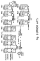
- the quality of the clock-in-apparatus is multiplexed with S1 byte of SOH as shown in Fig. 7 and an apparatus to connect has notice of it, so that the connected apparatus uses it for determining a clock in the apparatus to use.
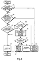
- control signal generation circuit 9 and multiplexing quality generation circuit 10 by carrying out the flowchart shown in Fig. 3, multiplexing qualities in consideration of timing loop is performed.
- the clock that was the origin of the clock in the apparatus is not a line clock (in case of NO in step 3A)
- the quality of the clock in the apparatus is multiplexed because there is no possibility to form a timing loop (step 3G).
- the following process is carried out when the clock that was the origin of the clock in the apparatus is a line clock (in case of YES in step 3A).
- the system and direction to multiplex the quality is compared with the output route information 93 of the control signal generation circuit 9, and it is judged whether or not the line clock that was the origin of the clock in the apparatus is the opposite direction to the quality multiplexing direction. Unless this judgement result is not the opposite direction (in case of NO in step 3B), because there is no possibility to form a timing loop, the quality of the clock in the apparatus is multiplexed (step 3G), and, in case of the opposite direction, the insertion direction of the quality is judged (step 3C).
- step 3H in case that the insertion direction is a wireless direction, "F" (Don't use for sync) is multiplexed with the quality (Q) even when the line clock that was the origin of the clock in the apparatus is not the same system (step 3H), in case of a wired direction, the process flow shifts to step 3D.
- step 3D in case that the line clock that was the origin of the clock in the apparatus and the insertion system of the quality are the same, "F” is multiplexed with the quality (step 3I), in the other cases, a priority established to the input from the opposite direction of the system to multiplex the quality is detected (step 3E).
- the quality of the clock in the apparatus is used as the quality to insert (step 3J), in the other cases, "F” is multiplexed with the quality (step 3I).
- NE1 to NE6 denote radio terminal station apparatus, and U1 to U2 do external clock sources, wherein U1 is a primary clock source of the highest quality on the network and U2 is a secondary clock source for spare, in the drawing, Q does a quality, besides, P does an established priority.
- P F .
- a line connected between NEs indicates a synchronous state of clock. Further, for simplifying the description, it is supposed that the number of systems of NE1 to NE2 is two, the number of systems of NE3 to NE6 is one, and this is a network branched into two directions in the wired transmission line direction of NE2.
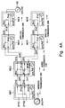
- Fig. 4A is a view showing a stationary state.
- the data signal sequence to input to NE1 is changed in its clock to the clock in the apparatus synchronized with the U1 output, in the clock change circuit.
- Q 2 that is the quality of the clock in the apparatus is multiplexed for NE3 and NE5 of the same direction as the line clock that was the origin of the clock in the apparatus
- Fig. 4B the clock of the highest quality among usable clocks is the output clock of U2.
- operations of NE2 are as follows.
- the network is synchronized in the order of (NE4 ⁇ NE3 ⁇ NE2 ⁇ NE1) and (NE4 ⁇ NE3 ⁇ NE2 ⁇ NE5 ⁇ NE6), and the whole of the network is synchronized with the output clock of U2.
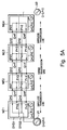
- NE1 to NE4 denote radio terminal station apparatus having the constructions of an embodiment of the present invention, wherein data signal sequences of two systems of SYS1 and SYS2 are transmitted.
- Fig. 5A is a view showing a synchronous state of the SDH network in a stationary state.
- Fig. 5B is a view in case that troubles arise on the transmission lines of SYS1 of (NE1 ⁇ NE2) and (NE2 ⁇ NE3).
- the clock in the apparatus becomes a signal synchronized with U1.
- the line clock of the data signal sequence input from NE2 to SYS2 is selected as the clock in the apparatus.
- radio terminal station apparatus has the construction to connect to the wired transmission line and wireless transmission line, and changes the processes for multiplexing the qualities in accordance with the transmission lines to connect, it can be applied in the transmission terminal station apparatus having the construction that both directions are wired transmission lines, by changing processing conditions.
- the quality of the SDH network can be kept high even when a trouble or the like arises on the transmission line, and the synchronous network construction never breaks due to a generation of a timing loop.
- a radio terminal station apparatus for an SDH network can be provided wherein the branched route can be synchronized with the clock of the high quality, and, without breaking the synchronous construction of the whole network, a generation of a timing loop can be also prevented.
Landscapes
- Engineering & Computer Science (AREA)
- Computer Networks & Wireless Communication (AREA)
- Signal Processing (AREA)
- Time-Division Multiplex Systems (AREA)
- Synchronisation In Digital Transmission Systems (AREA)
- Telephonic Communication Services (AREA)
Applications Claiming Priority (2)
| Application Number | Priority Date | Filing Date | Title |
|---|---|---|---|
| JP10035299A JP3052922B2 (ja) | 1998-02-18 | 1998-02-18 | 通信端局装置及びその動作クロック選定方法並びにその制御プログラムを記録した記録媒体 |
| JP3529998 | 1998-02-18 |
Publications (3)
| Publication Number | Publication Date |
|---|---|
| EP0938201A2 true EP0938201A2 (fr) | 1999-08-25 |
| EP0938201A3 EP0938201A3 (fr) | 2002-10-16 |
| EP0938201B1 EP0938201B1 (fr) | 2005-04-27 |
Family
ID=12437910
Family Applications (1)
| Application Number | Title | Priority Date | Filing Date |
|---|---|---|---|
| EP99103062A Expired - Lifetime EP0938201B1 (fr) | 1998-02-18 | 1999-02-16 | Station de terminal radio pour réseau SDH et méthode pour en sélectionner une horloge de travail |
Country Status (4)
| Country | Link |
|---|---|
| US (1) | US6807194B1 (fr) |
| EP (1) | EP0938201B1 (fr) |
| JP (1) | JP3052922B2 (fr) |
| DE (1) | DE69924902T2 (fr) |
Cited By (1)
| Publication number | Priority date | Publication date | Assignee | Title |
|---|---|---|---|---|
| WO2014083640A1 (fr) * | 2012-11-28 | 2014-06-05 | 三菱電機株式会社 | Appareil de communication, système de communication et procédé de synchronisation temporelle |
Families Citing this family (6)
| Publication number | Priority date | Publication date | Assignee | Title |
|---|---|---|---|---|
| CN1302629C (zh) * | 2003-12-18 | 2007-02-28 | 华为技术有限公司 | 一种多信号复用处理过程中时钟同步方法和装置 |
| CN101068133B (zh) * | 2007-06-12 | 2011-05-04 | 华为技术有限公司 | 时间同步方法、网络通信系统及其设备 |
| US7929574B2 (en) * | 2007-11-30 | 2011-04-19 | Alcatel Lucent | Advanced clock distribution mechanism for circuit emulation applications |
| JP5233684B2 (ja) * | 2009-01-09 | 2013-07-10 | 日本電気株式会社 | クロック選択装置、クロック選択方法およびクロック選択プログラム |
| CN101931524A (zh) | 2009-06-25 | 2010-12-29 | 中兴通讯股份有限公司 | 一种同步数字传输网的时钟源选择方法 |
| CN104216779B (zh) * | 2014-09-28 | 2018-10-02 | 北京经纬恒润科技有限公司 | 一种中断执行方法及装置 |
Family Cites Families (7)
| Publication number | Priority date | Publication date | Assignee | Title |
|---|---|---|---|---|
| JP3197793B2 (ja) * | 1995-07-03 | 2001-08-13 | 富士通株式会社 | 無線装置 |
| GB9605013D0 (en) * | 1996-03-08 | 1996-05-08 | Northern Telecom Ltd | Network synchronisation |
| JP3681225B2 (ja) * | 1996-07-31 | 2005-08-10 | 富士通株式会社 | シンクロナイゼイション・メッセージ送信装置 |
| JP3791983B2 (ja) * | 1996-10-29 | 2006-06-28 | 富士通株式会社 | シンクロナイゼーションメッセージによるアクティブリファレンスの切替え装置 |
| JPH11122207A (ja) * | 1997-10-14 | 1999-04-30 | Fujitsu Ltd | 伝送装置および同期ネットワークにおける信号伝送方法 |
| JP3414627B2 (ja) * | 1997-10-20 | 2003-06-09 | 富士通株式会社 | 同期装置 |
| JP3569127B2 (ja) * | 1998-04-20 | 2004-09-22 | 富士通株式会社 | Sdh無線伝送装置 |
-
1998
- 1998-02-18 JP JP10035299A patent/JP3052922B2/ja not_active Expired - Fee Related
-
1999
- 1999-02-11 US US09/248,096 patent/US6807194B1/en not_active Expired - Lifetime
- 1999-02-16 DE DE69924902T patent/DE69924902T2/de not_active Expired - Lifetime
- 1999-02-16 EP EP99103062A patent/EP0938201B1/fr not_active Expired - Lifetime
Cited By (1)
| Publication number | Priority date | Publication date | Assignee | Title |
|---|---|---|---|---|
| WO2014083640A1 (fr) * | 2012-11-28 | 2014-06-05 | 三菱電機株式会社 | Appareil de communication, système de communication et procédé de synchronisation temporelle |
Also Published As
| Publication number | Publication date |
|---|---|
| JP3052922B2 (ja) | 2000-06-19 |
| DE69924902T2 (de) | 2005-09-29 |
| US6807194B1 (en) | 2004-10-19 |
| EP0938201A3 (fr) | 2002-10-16 |
| DE69924902D1 (de) | 2005-06-02 |
| EP0938201B1 (fr) | 2005-04-27 |
| JPH11234237A (ja) | 1999-08-27 |
Similar Documents
| Publication | Publication Date | Title |
|---|---|---|
| US5857092A (en) | Interface apparatus for SDH/SONET interconnection | |
| US5416768A (en) | Interconnecting communications networks | |
| US6839858B1 (en) | System for clock synchronization | |
| US6163551A (en) | Network element for use in synchronous digital communications system and central clock generator | |
| US8194704B2 (en) | Network equipment | |
| JPWO2001080478A1 (ja) | Wdmネットワークの光クロック信号分配システム | |
| EP0938201B1 (fr) | Station de terminal radio pour réseau SDH et méthode pour en sélectionner une horloge de travail | |
| US6169753B1 (en) | Transmission device and signal transmission method in synchronous network | |
| US8126102B2 (en) | Communication apparatus and control method | |
| US8204085B1 (en) | Virtual concatenation for parallel data streams | |
| JP2001177491A (ja) | 光伝送システム、同期多重伝送システム及び同期多重伝送方法 | |
| ITMI20000545A1 (it) | Metodo ed apparato per trasmettere/ricevere segnali digitali di livello stm-4(sdh) o sts-12(sonet) su due portanti rf in una sezione di rige | |
| US6628674B1 (en) | Apparatus depending on timing source for synchronization | |
| KR0151908B1 (ko) | 동기식 디지틀 회선분배 장치 | |
| US5870403A (en) | Apparatus and a method for establishing signal synchronization between lines | |
| US6560245B1 (en) | Telecommunications system | |
| US20030112463A1 (en) | Path control method, a transmitter circuit, and a receiver circuit | |
| US7181545B2 (en) | Network synchronization architecture for a Broadband Loop Carrier (BLC) system | |
| JP4181867B2 (ja) | 同期網確立方法及びその装置 | |
| US6236665B1 (en) | Transmission device | |
| JP2677198B2 (ja) | 無線通信方式 | |
| EP0910189A2 (fr) | Synchronisation de réseau avec HNS/SONET | |
| KR100263383B1 (ko) | 광 가입자 전송장치에 있어서의 분기/결합 장치 | |
| JP3492558B2 (ja) | リング型ネットワークシステム | |
| JP2621801B2 (ja) | 無線通信方式 |
Legal Events
| Date | Code | Title | Description |
|---|---|---|---|
| PUAI | Public reference made under article 153(3) epc to a published international application that has entered the european phase |
Free format text: ORIGINAL CODE: 0009012 |
|
| AK | Designated contracting states |
Kind code of ref document: A2 Designated state(s): AT BE CH CY DE DK ES FI FR GB GR IE IT LI LU MC NL PT SE |
|
| AX | Request for extension of the european patent |
Free format text: AL;LT;LV;MK;RO;SI |
|
| PUAL | Search report despatched |
Free format text: ORIGINAL CODE: 0009013 |
|
| AK | Designated contracting states |
Kind code of ref document: A3 Designated state(s): AT BE CH CY DE DK ES FI FR GB GR IE IT LI LU MC NL PT SE |
|
| AX | Request for extension of the european patent |
Free format text: AL;LT;LV;MK;RO;SI |
|
| RIC1 | Information provided on ipc code assigned before grant |
Free format text: 7H 04J 3/06 A |
|
| 17P | Request for examination filed |
Effective date: 20020909 |
|
| 17Q | First examination report despatched |
Effective date: 20030319 |
|
| AKX | Designation fees paid |
Designated state(s): DE FR GB |
|
| GRAP | Despatch of communication of intention to grant a patent |
Free format text: ORIGINAL CODE: EPIDOSNIGR1 |
|
| GRAS | Grant fee paid |
Free format text: ORIGINAL CODE: EPIDOSNIGR3 |
|
| GRAA | (expected) grant |
Free format text: ORIGINAL CODE: 0009210 |
|
| AK | Designated contracting states |
Kind code of ref document: B1 Designated state(s): DE FR GB |
|
| REG | Reference to a national code |
Ref country code: GB Ref legal event code: FG4D |
|
| REG | Reference to a national code |
Ref country code: IE Ref legal event code: FG4D |
|
| REF | Corresponds to: |
Ref document number: 69924902 Country of ref document: DE Date of ref document: 20050602 Kind code of ref document: P |
|
| PLBE | No opposition filed within time limit |
Free format text: ORIGINAL CODE: 0009261 |
|
| STAA | Information on the status of an ep patent application or granted ep patent |
Free format text: STATUS: NO OPPOSITION FILED WITHIN TIME LIMIT |
|
| ET | Fr: translation filed | ||
| 26N | No opposition filed |
Effective date: 20060130 |
|
| PGFP | Annual fee paid to national office [announced via postgrant information from national office to epo] |
Ref country code: FR Payment date: 20120221 Year of fee payment: 14 |
|
| PGFP | Annual fee paid to national office [announced via postgrant information from national office to epo] |
Ref country code: DE Payment date: 20120208 Year of fee payment: 14 |
|
| REG | Reference to a national code |
Ref country code: FR Ref legal event code: ST Effective date: 20131031 |
|
| REG | Reference to a national code |
Ref country code: DE Ref legal event code: R119 Ref document number: 69924902 Country of ref document: DE Effective date: 20130903 |
|
| PG25 | Lapsed in a contracting state [announced via postgrant information from national office to epo] |
Ref country code: FR Free format text: LAPSE BECAUSE OF NON-PAYMENT OF DUE FEES Effective date: 20130228 Ref country code: DE Free format text: LAPSE BECAUSE OF NON-PAYMENT OF DUE FEES Effective date: 20130903 |
|
| PGFP | Annual fee paid to national office [announced via postgrant information from national office to epo] |
Ref country code: GB Payment date: 20160210 Year of fee payment: 18 |
|
| GBPC | Gb: european patent ceased through non-payment of renewal fee |
Effective date: 20170216 |
|
| PG25 | Lapsed in a contracting state [announced via postgrant information from national office to epo] |
Ref country code: GB Free format text: LAPSE BECAUSE OF NON-PAYMENT OF DUE FEES Effective date: 20170216 |