EP0938236A2 - Verfahren zum Generieren einer Einsprungsstelle in einen Bildatenstrom und Vorrichtung zur Durchführung des Verfahrens - Google Patents
Verfahren zum Generieren einer Einsprungsstelle in einen Bildatenstrom und Vorrichtung zur Durchführung des Verfahrens Download PDFInfo
- Publication number
- EP0938236A2 EP0938236A2 EP99440024A EP99440024A EP0938236A2 EP 0938236 A2 EP0938236 A2 EP 0938236A2 EP 99440024 A EP99440024 A EP 99440024A EP 99440024 A EP99440024 A EP 99440024A EP 0938236 A2 EP0938236 A2 EP 0938236A2
- Authority
- EP
- European Patent Office
- Prior art keywords
- image
- intraframe
- image data
- time delay
- interframe
- Prior art date
- Legal status (The legal status is an assumption and is not a legal conclusion. Google has not performed a legal analysis and makes no representation as to the accuracy of the status listed.)
- Granted
Links
Images
Classifications
-
- H—ELECTRICITY
- H04—ELECTRIC COMMUNICATION TECHNIQUE
- H04N—PICTORIAL COMMUNICATION, e.g. TELEVISION
- H04N7/00—Television systems
- H04N7/01—Conversion of standards, e.g. involving analogue television standards or digital television standards processed at pixel level
- H04N7/0117—Conversion of standards, e.g. involving analogue television standards or digital television standards processed at pixel level involving conversion of the spatial resolution of the incoming video signal
- H04N7/0122—Conversion of standards, e.g. involving analogue television standards or digital television standards processed at pixel level involving conversion of the spatial resolution of the incoming video signal the input and the output signals having different aspect ratios
-
- H—ELECTRICITY
- H04—ELECTRIC COMMUNICATION TECHNIQUE
- H04N—PICTORIAL COMMUNICATION, e.g. TELEVISION
- H04N19/00—Methods or arrangements for coding, decoding, compressing or decompressing digital video signals
- H04N19/40—Methods or arrangements for coding, decoding, compressing or decompressing digital video signals using video transcoding, i.e. partial or full decoding of a coded input stream followed by re-encoding of the decoded output stream
-
- H—ELECTRICITY
- H04—ELECTRIC COMMUNICATION TECHNIQUE
- H04N—PICTORIAL COMMUNICATION, e.g. TELEVISION
- H04N19/00—Methods or arrangements for coding, decoding, compressing or decompressing digital video signals
- H04N19/85—Methods or arrangements for coding, decoding, compressing or decompressing digital video signals using pre-processing or post-processing specially adapted for video compression
-
- H—ELECTRICITY
- H04—ELECTRIC COMMUNICATION TECHNIQUE
- H04N—PICTORIAL COMMUNICATION, e.g. TELEVISION
- H04N21/00—Selective content distribution, e.g. interactive television or video on demand [VOD]
- H04N21/80—Generation or processing of content or additional data by content creator independently of the distribution process; Content per se
- H04N21/83—Generation or processing of protective or descriptive data associated with content; Content structuring
- H04N21/845—Structuring of content, e.g. decomposing content into time segments
- H04N21/8455—Structuring of content, e.g. decomposing content into time segments involving pointers to the content, e.g. pointers to the I-frames of the video stream
Definitions
- the invention relates to a method for generating a Entry point into an image data stream from interframe-encoded image data and an apparatus for performing the method.
- service-on-demand systems real-time image data are encoded in a server and video image data in a video server encoded and stored on demand by a customer to be transferred to the respective customer.
- the image information of the Real-time image data and the video image data is divided into individual images that juxtaposed e.g. a recording of a live broadcast or one Result in video film.
- the Transmission medium e.g. a broadband cable
- the cable in the connection network for data reduction in the server / video server Compression of real-time / video image data by encoding after Interframe procedure performed.
- the Transmission medium e.g. a broadband cable
- the cable in the connection network for data reduction in the server / video server Compression of real-time / video image data by encoding after Interframe procedure performed.
- a disadvantage with the transmission interframe encoded image data is that no jump into one continuous image data stream is possible because knowledge of the previous frame would be required.
- the object of the invention is a method and an apparatus for Implementation of the procedure to create a suitable one To allow entry into an image data stream that, except for the Initial image, made up exclusively of interframe-encoded image data is.
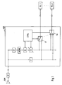
- FIG. 1 shows a first device according to the invention for Generate one or more entry points into an image data stream from interframe-encoded image data.
- the camera CAM takes e.g. a live broadcast and carries the image data then the encoder K1.
- the initial image is in the encoder K1 encoded according to the intra-frame method and all the initial image the following images are encoded according to the interframe method to minimize required transmission capacity.
- Such an encoder is known for example from DE 3613343, where it is used as a hybrid encoder is designated.
- the encoded image data is then the Device fed before.
- the device VOR and the video telephones TEL1 to TELn are e.g. about a Transmission network, e.g. ISDN or B-ISDN or by radio with each other in connection.
- the device VOR includes a time delay element ⁇ 1 for the time Delaying from the encoder K1 and in the device BEFORE received intra- and interframe-encoded image data by one fixed value, e.g. a few milliseconds.
- the delay of the Time delay element ⁇ 1 is required to subscribers who watch the live broadcast want to track to generate entry points.
- the Participants will be delayed the live broadcast by the fixed amount offered, which is not a disadvantage, since the delay is so is small that it is not visible to the human eye due to its sluggishness is noticeable.
- the device VOR further includes a series connection a decoder D1, an intermediate memory MEMO, an encoder K2 and a time delay element ⁇ 2 for generating the entry points.
- the decoder D1 is used to decode at least one intraframe-coded Picture, e.g. the opening picture of a live broadcast and of interframe encoded pictures, e.g. those sequentially following the initial image Single images. Due to the receipt of the intraframe-encoded Initial image, all other individual images can also be decoded, although these are interframe encoded since all previous frames are known.
- intraframe-coded Picture e.g. the opening picture of a live broadcast and of interframe encoded pictures, e.g. those sequentially following the initial image Single images. Due to the receipt of the intraframe-encoded Initial image, all other individual images can also be decoded, although these are interframe encoded since all previous frames are known.
- the decoded images are cached.
- Decoder D1 and buffer MEMO form e.g. Parts of a Videophones that connect to the CAM camera and the K1 encoder builds up.
- the encoder K2 is used to encode buffered images according to the intraframe process.
- the structure of the encoder K2 can be quite or partially correspond to the structure of the encoder K1.
- the entry points are generated.
- the MEMO buffer Image data that are comparable to the image data that the camera CAM available.
- the encoder K2 can thus in the same way as the encoder K1 generate intraframe-encoded image data without Information about previous images is needed.
- the time delay element ⁇ 2 serves to delay the time in Encoders generated intraframe-encoded images, the temporal Delay of the time delay element ⁇ 2 is less than the time Delay of the time delay element ⁇ 1.
- the device VOR further includes a control unit CTRL which e.g. is made up of a microprocessor, e.g. also part of one Videophones is.
- the control unit CTRL is provided to the encoder K2 and to drive the time delay element ⁇ 2.
- the control unit CTRL is programmed in such a way that it encodes the K2 controls such that the encoder K2 to from the control unit CTRL a cached image after the defined times Coded intraframe process.
- the encoder K2 is, for example, in one inactive state in which it does not make any coding. He'll be first by controlling the control unit CTRL, which e.g. of a Participants to jump in and broadcast a live broadcast was asked to be set to the active state in which the encoder K2 an encoding of the most recent cached frame the intra-frame procedure.
- This intraframe encoded frame then serves as an entry point for the transmission of the live broadcast Attendees.
- the timing of the transfer of the entry point is adjusted through the delay element ⁇ 2 the transmission of the single image Entry point following and coded in the interframe method Single images connected so that there is a continuous data stream results.
- the time delay of the time delay element ⁇ 2 is determined by the Control unit CTRL set by the encoder K2 information about how much capacity the intraframe-coded single image receives Entry point requires what the delay is for Let transfer be calculated.
- the time delay of the Time delay element ⁇ 2 is determined from the difference in time Delay of the time delay element ⁇ 1 to delay that for the Generation of the intraframe-coded single image of the entry point is required.
- the transmission of the intraframe-coded single image of the Entry point and the transmission of the intraframe-coded Frame of the entry point sequentially following interframe frames are therefore adjusted to each other in time to make the continuous To generate data stream.
- Each switch S1, Sn has two inputs and an exit.
- Each switch S1, Sn has an input with the Output of the time delay element ⁇ 1 and the other input with the Output of the time delay element ⁇ 2 connected.
- Each switch is S1, Sn can be controlled by the control unit CTRL in such a way that at each output a continuous image data stream is present when a request from a Participant for transmission e.g. a live broadcast and one Entry point was generated.
- Switch S1 is always with, for example Time delay element ⁇ 2 connected.
- this entry point is instructed by the Control unit CRTL generated and transmitted by the encoder K2.
- the time delay element ⁇ 2 arrives at the entry point with a delay Switch S1, from w it is forwarded to the subscriber.
- the desk Sl is sent with the Time delay element ⁇ 1 connected, so that the transmission of the Entry point connects the following pictures to the participant.
- Switch S1 ends with the Time delay element ⁇ 2 connected.
- steps c) to e) are required be performed.
- Steps a) and b) are for each live broadcast executed only once, with step b) parallel to step c) to e), which can be carried out several times in succession, is performed.
- steps c) to e) need only once be performed.
- One of two of the switches S1 to Sn can simultaneous assignment of the continuous image data streams over two separate transmission lines to two independent participants respectively.
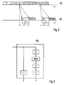
- Frame 1 is the initial image that after the Intra-frame encoded method is encoded.
- the individual pictures 2 to 14 are encoded according to the interframe method. For each of the frames 2 to 14 less transmission capacity is required, as for the single picture 1.
- the transmission time is plotted on the t-axis.
- FIG. 2b shows two entry points into the image data stream from FIG. 2a.
- Out the interframe-coded frame 4 is decoded by Decoder D1 and intermediate storage in the intermediate memory MEMO Intra-frame coded single image generated in the encoder K2, which as Entry point serves.
- the delay of the time delay element ⁇ 2 becomes chosen so that when sending the intraframe-coded frame 4 the transmission of the delay of the time delay element ⁇ 1 delayed frame 5 connects without interruption, so that a continuous image data stream arises.
- Intra-frame-coded single image 11 is generated as a further entry point serves.
- the delay of the time delay element ⁇ 2 is chosen so that when sending the intraframe-coded frame 11, the Transmission of the delay of the time delay element ⁇ 1 delayed frame 12 connects without interruption.
- Fig. 3 shows a second device according to the invention for Generate multiple entry points into an image data stream interframe-encoded image data.
- the device VOR includes a Time delay element ⁇ 1 and a series circuit consisting of a decoder D1, a buffer MEMO, an encoder K2 and one Time delay element ⁇ 2.
- These modules correspond to the 1 of the same name from Fig. in their structure and their Functioning with the difference that the encoder K2 and that Time delay element ⁇ 2 is not controlled by a control unit CTRL but at fixed times, e.g.
- a buffered image according to the intra-frame process encode and adapt to the delay of the Send out time delay element ⁇ 1.
- the intraframe encoded pictures serve as possible entry points. They become parallel to that continuous image data stream, e.g. over two separate Transmission channels of the ISDN or in time division multiplexing over one channel. Of the Recipients then have the option of possible entry points in to jump in the continuous image data stream. Instead of one adapted transmission of possible entry points and the continuous image data stream can also be on the time delay ⁇ 2 can be dispensed with. The recipient must then ensure that an adapted entry into the image data stream takes place. This is e.g. at Transmission routes make sense where runtime differences for e.g. Data transmitted over two separate ISDN transmission channels cannot be excluded, so that the adjustment of the possible Entry points to the continuous image data stream during transmission could be changed in an unpredictable way.
Landscapes
- Engineering & Computer Science (AREA)
- Multimedia (AREA)
- Signal Processing (AREA)
- Computer Graphics (AREA)
- Compression Or Coding Systems Of Tv Signals (AREA)
- Two-Way Televisions, Distribution Of Moving Picture Or The Like (AREA)
- Television Signal Processing For Recording (AREA)
- Compression, Expansion, Code Conversion, And Decoders (AREA)
Abstract
Description
- Fig. 1
- eine schematische Darstellung einer ersten erfindungsgemäßen Vorrichtung,
- Fig. 2
- zwei Diagramme beinhaltend einen interframe-kodierten Datenstrom und zwei Einsprungstellen, und
- Fig. 3
- eine schematische Darstellung einer zweiten erfindungsgemäßen Vorrichtung.
Claims (7)
- Verfahren zum Generieren einer Einsprungsstelle in einen Bilddatenstrom aus interframe-kodierten Bilddaten mit den folgenden Schritten:a) Empfang von intraframe-kodierten Bilddaten eines Anfangsbildes sowie Dekodieren und Zwischenspeichern des Anfangsbildes,b) Empfang von interframe-kodierten Bilddaten von dem Anfangsbild sequentiell folgenden Einzelbildern sowie Dekodieren und Zwischenspeichern des jeweils zuletzt empfangenen Einzelbildes,c) Empfang einer Anforderung zum Generieren einer Einsprungstelle,d) Kodieren des nächsten zwischenzuspeichernden Einzelbildes nach dem Intraframe-Verfahren bei gleichzeitigem Zeitverzögern aller dem nächsten zwischenzuspeichernden Einzelbild folgenden Bildern um einen vorbestimmten Wert,e) Zeitverzögern des intraframe-kodierten Einzelbildes derart, daß nach einer Aussendung des intraframe-kodierten Einzelbildes die Aussendung des dem intraframe-kodierten Einzelbild sequentiell folgenden interframe-kodierten Einzelbildes zeitlich angepaßt erfolgen kann.
- Verfahren zum Generieren von Einsprungsstellen in einen Bilddatenstrom aus interframe-kodierten Bilddaten mit den Schritten a) bis e) nach Anspruch 1, dadurch gekennzeichnet, daß für jede weitere Einsprungstelle die Schritte c) bis e) durchgeführt werden.
- Vorrichtung ( VOR ) zur Durchführung des Verfahrens nach Anspruch 1 oder 2, beinhaltend : ein erstes Zeitverzögerungsglied (τ1) zum zeitlichen Verzögern von empfangenen intra- und interframe-kodierten Bilddaten um einen festen Wert, einen Dekodierer (D1) zum Dekodieren mindestens eines intraframe-kodierten Bildes und von interframe-kodierten Bilder, einem dem Dekodierer (D1) nachgeschalteten Zwischenspeicher ( MEMO ) zum Zwischenspeichern der dekodierten Bilder, einem dem Zwischenspeicher ( MEMO ) nachgeschalteten Kodierer ( K2 ) zum Kodieren mindestens eines zwischengespeicherten Bildes nach dem Intraframe-Verfahren, und einem dem Kodierer ( K2 ) nachgeschalteten zweiten Zeitverzögerungsglied (τ2) zum zeitlichen Verzögern des mindestens einem interframe-kodierten Bildes, wobei die zeitliche Verzögerung des zweiten Zeitverzögerungsglieds (τ2) kleiner ist als die zeitliche Verzögerung des ersten Zeitverzögerungsglieds (τ1).
- Vorrichtung ( VOR ) nach Anspruch 3, dadurch gekennzeichnet, daß eine Steuereinheit ( CTRL ) vorgesehen ist, die geeignet ist, den Kodierer ( K2 ) derart anzusteuern, daß der Kodierer ( K2 ) zu einem von der Steuereinheit ( CTRL ) definierten Zeitpunkt ein zwischengespeichertes Bild nach dem Intraframe-Verfahren kodiert.
- Vorrichtung ( VOR ) nach Anspruch 4, dadurch gekennzeichnet, daß die Steuereinheit ( CTRL ) geeignet ist, die zeitliche Verzögerung des zweiten Zeitverzögerungsglieds (τ2) einzustellen, um die Aussendung des intraframe-kodierten Einzelbildes und die Aussendung des dem intraframe-kodierten Einzelbild sequentiell folgenden interframe-kodierten Einzelbildes zeitlich aneinander anzupassen.
- Vorrichtung ( VOR ) nach Anspruch 5, dadurch gekennzeichnet, daß mindestens ein von der Steuereinheit (CTRL) ansteuerbarer Schalter ( S1, Sn ) vorgesehen ist, daß jeder Schalter ( S1, Sn ) zwei Eingänge und einen Ausgang aufweist, daß bei jedem Schalter ( S1, Sn ) ein Eingang mit dem Ausgang des ersten Zeitverzögerungsglieds (τ1), der andere Eingang mit dem Ausgang des zweiten Zeitverzögerungsglieds (τ2) verbunden ist, und daß jeder Schalter ( S1, Sn ) derart ansteuerbar ist, daß an jedem Ausgang ein kontinuierlicher Bildatenstrom anliegt.
- Vorrichtung (VOR) nach Anspruch 3, dadurch gekennzeichnet, daß der Kodierer ( K2 ) geeignet ist, zu fest definierten Zeitpunkten ein zwischengespeichertes Bild nach dem Intraframe-Verfahren zu kodieren.
Applications Claiming Priority (2)
| Application Number | Priority Date | Filing Date | Title |
|---|---|---|---|
| DE19806913A DE19806913A1 (de) | 1998-02-19 | 1998-02-19 | Verfahren zum Generieren einer Einsprungstelle in einen Bilddatenstrom und Vorrichtung zur Durchführung des Verfahrens |
| DE19806913 | 1998-02-19 |
Publications (3)
| Publication Number | Publication Date |
|---|---|
| EP0938236A2 true EP0938236A2 (de) | 1999-08-25 |
| EP0938236A3 EP0938236A3 (de) | 2001-03-21 |
| EP0938236B1 EP0938236B1 (de) | 2006-11-08 |
Family
ID=7858259
Family Applications (1)
| Application Number | Title | Priority Date | Filing Date |
|---|---|---|---|
| EP99440024A Expired - Lifetime EP0938236B1 (de) | 1998-02-19 | 1999-02-05 | Verfahren zum Generieren einer Einsprungsstelle in einen Bildatenstrom und Vorrichtung zur Durchführung des Verfahrens |
Country Status (5)
| Country | Link |
|---|---|
| US (1) | US6240136B1 (de) |
| EP (1) | EP0938236B1 (de) |
| JP (1) | JP4372881B2 (de) |
| CA (1) | CA2261180A1 (de) |
| DE (2) | DE19806913A1 (de) |
Families Citing this family (2)
| Publication number | Priority date | Publication date | Assignee | Title |
|---|---|---|---|---|
| FR2943877B1 (fr) * | 2009-03-24 | 2014-04-04 | Streamwide | Procede et dispositif de stockage d'une partie d'un flux video |
| KR102077556B1 (ko) | 2012-06-28 | 2020-02-14 | 엑시스 에이비 | 가상 인트라-프레임을 사용하여 비디오 콘텐츠를 인코딩하기 위한 시스템 및 방법 |
Family Cites Families (17)
| Publication number | Priority date | Publication date | Assignee | Title |
|---|---|---|---|---|
| DE3613343A1 (de) | 1986-04-19 | 1987-10-22 | Philips Patentverwaltung | Hybrid-codierer |
| DE3831277A1 (de) | 1988-09-14 | 1990-03-15 | Philips Patentverwaltung | Verfahren zur speicherung und wiedergabe von videosignalen |
| US5535008A (en) * | 1993-03-16 | 1996-07-09 | Victor Company Of Japan, Ltd. | Method for jump-reproducing video data of moving picture coded with high efficiency |
| CA2127347A1 (en) * | 1993-07-07 | 1995-01-08 | Donald F. Hooper | Segmented video on-demand system |
| WO1995008823A1 (en) * | 1993-09-21 | 1995-03-30 | Sony Corporation | Method and device for transmitting data, data decoder, and data recording medium |
| EP0656729B1 (de) * | 1993-12-01 | 2000-02-09 | Matsushita Electric Industrial Co., Ltd. | Verfahren und Vorrichtung zum Editieren oder zur Mischung von komprimierten Bildern |
| JPH07212766A (ja) * | 1994-01-18 | 1995-08-11 | Matsushita Electric Ind Co Ltd | 動画像圧縮データ切り換え装置 |
| EP0982942B1 (de) * | 1994-07-29 | 2004-06-02 | Sharp Kabushiki Kaisha | Fernsehübermittlungsanlage mit Speichermöglichkeit |
| DE69633808T2 (de) * | 1995-04-10 | 2005-11-03 | Hewlett-Packard Development Co., L.P., Houston | Interaktives Video-auf-Abrufsystem mit Paketübertragung über eine ATM-Fernmeldeleitung |
| JP3484834B2 (ja) * | 1995-07-28 | 2004-01-06 | ソニー株式会社 | データ符号化/復号化方法および装置 |
| SG74566A1 (en) * | 1995-08-23 | 2000-08-22 | Sony Corp | Encoding/decoding fields of predetermined field polarity apparatus and method |
| DE19531847A1 (de) * | 1995-08-29 | 1997-03-06 | Sel Alcatel Ag | Vorrichtung zur Speicherung von Videobilddaten |
| US5845083A (en) * | 1996-03-07 | 1998-12-01 | Mitsubishi Semiconductor America, Inc. | MPEG encoding and decoding system for multimedia applications |
| DE19626108A1 (de) * | 1996-06-28 | 1998-01-08 | Thomson Brandt Gmbh | Verfahren und Vorrichtung zur Codierung von digitalen Bildsignalen |
| DE19644650A1 (de) * | 1996-10-26 | 1998-04-30 | Thomson Brandt Gmbh | Verfahren zur Bearbeitung von digital codierten Bildern einer Bildsequenz sowie Vorrichtung zur Durchführung des Verfahrens und Vorrichtung zur Zwischenspeicherung von decodierten Bildern |
| US6167083A (en) * | 1997-04-04 | 2000-12-26 | Avid Technology, Inc. | Computer system and process for capture editing and playback of motion video compressed using interframe and intraframe techniques |
| US6151443A (en) * | 1997-05-16 | 2000-11-21 | Indigita Corporation | Digital video and data recorder |
-
1998
- 1998-02-19 DE DE19806913A patent/DE19806913A1/de not_active Withdrawn
-
1999
- 1999-02-05 EP EP99440024A patent/EP0938236B1/de not_active Expired - Lifetime
- 1999-02-05 DE DE59913968T patent/DE59913968D1/de not_active Expired - Lifetime
- 1999-02-10 JP JP03265499A patent/JP4372881B2/ja not_active Expired - Fee Related
- 1999-02-18 CA CA002261180A patent/CA2261180A1/en not_active Abandoned
- 1999-02-18 US US09/252,453 patent/US6240136B1/en not_active Expired - Lifetime
Also Published As
| Publication number | Publication date |
|---|---|
| DE59913968D1 (de) | 2006-12-21 |
| JPH11284955A (ja) | 1999-10-15 |
| DE19806913A1 (de) | 1999-08-26 |
| CA2261180A1 (en) | 1999-08-19 |
| EP0938236A3 (de) | 2001-03-21 |
| EP0938236B1 (de) | 2006-11-08 |
| US6240136B1 (en) | 2001-05-29 |
| JP4372881B2 (ja) | 2009-11-25 |
Similar Documents
| Publication | Publication Date | Title |
|---|---|---|
| DE69229773T2 (de) | Statistischer Multiplexer für ein Multikanal-Bildkomprimierungssystem und Demultiplexer | |
| DE69011422T2 (de) | Paketstruktur und Übertragung der von einem Videosignal-Kodierer erzeugten Information. | |
| DE19635116C2 (de) | Verfahren zur Videokommunikation | |
| EP0796015B1 (de) | Einrichtung und Dienst zur Übertragung von Videobilddaten sowie Einrichtung von Anforderungssignalen | |
| DE69507410T2 (de) | Interaktives Videosystem | |
| DE69215973T2 (de) | Multiplexer mit Einfügung von digitalen Paketen mit verschiedenen Prioritäten in einem Übertragungskanal | |
| DE69214217T2 (de) | Multipoint-Telekonferenz-System mit Anwendung von Kommunikationskanälen in Ringkonfiguration | |
| DE3614361C2 (de) | ||
| DE60114650T2 (de) | Adaptive videobestellung | |
| DE10043188A1 (de) | Fehlerkorrekturverfahren für Videokompressionskodierung unter Verwendung von mehreren Referenzpuffern und einem Nachrichtenkanal | |
| EP2422517A1 (de) | Verfahren und vorrichtung zur modifikation eines kodierten datenstroms | |
| DE19631939A1 (de) | Digitaler ISDN-Video-Server | |
| EP0762770A2 (de) | Vorrichtung zur Speicherung von Videobilddaten | |
| DE69928494T2 (de) | Videosignalkompression | |
| EP0938236B1 (de) | Verfahren zum Generieren einer Einsprungsstelle in einen Bildatenstrom und Vorrichtung zur Durchführung des Verfahrens | |
| AT405588B (de) | Verfahren zur wiederholung fehlerhaft übertragener daten | |
| DE1512833B2 (de) | Nachrichtemnterpolationsanlage | |
| DE2904981A1 (de) | Verfahren zur uebertragung von fernsehsignalen und system zur durchfuehrung des verfahrens | |
| DE69503954T2 (de) | Peripheriegerät für Multi-Videokonferenz über Satellit | |
| EP2206311B1 (de) | Verfahren und system zur bandbreite-optimierten übertragung von hdtv-datenströmen über ein ip-basiertes verteilernetz | |
| DE69523201T2 (de) | Verfahren und Vorrichtung zur Wiedergabe einer von einer entfernten Quelle empfangenen digitalen Bildfolge | |
| WO2009018791A1 (de) | Verfahren und system zum reduzieren der umschaltlücke bei einem programmwechsel in einer digitalen videoumgebung | |
| DE69007843T2 (de) | Sende- und Empfangssystem zum Übertragen von beweglichen Farbbildern und Ton über unabhängige Kanäle. | |
| DE69326037T2 (de) | System zur Speicherung und Wiedergabe von Bildern | |
| DE69726417T2 (de) | Verfahren und Vorrichtung zur Kodierung von Bewegtbildern |
Legal Events
| Date | Code | Title | Description |
|---|---|---|---|
| PUAI | Public reference made under article 153(3) epc to a published international application that has entered the european phase |
Free format text: ORIGINAL CODE: 0009012 |
|
| AK | Designated contracting states |
Kind code of ref document: A2 Designated state(s): DE ES FR GB IT SE |
|
| AX | Request for extension of the european patent |
Free format text: AL;LT;LV;MK;RO;SI |
|
| PUAL | Search report despatched |
Free format text: ORIGINAL CODE: 0009013 |
|
| AK | Designated contracting states |
Kind code of ref document: A3 Designated state(s): AT BE CH CY DE DK ES FI FR GB GR IE IT LI LU MC NL PT SE |
|
| AX | Request for extension of the european patent |
Free format text: AL;LT;LV;MK;RO;SI |
|
| 17P | Request for examination filed |
Effective date: 20010726 |
|
| AKX | Designation fees paid |
Free format text: DE ES FR GB IT SE |
|
| GRAP | Despatch of communication of intention to grant a patent |
Free format text: ORIGINAL CODE: EPIDOSNIGR1 |
|
| GRAS | Grant fee paid |
Free format text: ORIGINAL CODE: EPIDOSNIGR3 |
|
| GRAA | (expected) grant |
Free format text: ORIGINAL CODE: 0009210 |
|
| AK | Designated contracting states |
Kind code of ref document: B1 Designated state(s): DE ES FR GB IT SE |
|
| REG | Reference to a national code |
Ref country code: GB Ref legal event code: FG4D Free format text: NOT ENGLISH |
|
| GBT | Gb: translation of ep patent filed (gb section 77(6)(a)/1977) |
Effective date: 20061108 |
|
| REF | Corresponds to: |
Ref document number: 59913968 Country of ref document: DE Date of ref document: 20061221 Kind code of ref document: P |
|
| PG25 | Lapsed in a contracting state [announced via postgrant information from national office to epo] |
Ref country code: SE Free format text: LAPSE BECAUSE OF FAILURE TO SUBMIT A TRANSLATION OF THE DESCRIPTION OR TO PAY THE FEE WITHIN THE PRESCRIBED TIME-LIMIT Effective date: 20070208 |
|
| PG25 | Lapsed in a contracting state [announced via postgrant information from national office to epo] |
Ref country code: ES Free format text: LAPSE BECAUSE OF FAILURE TO SUBMIT A TRANSLATION OF THE DESCRIPTION OR TO PAY THE FEE WITHIN THE PRESCRIBED TIME-LIMIT Effective date: 20070219 |
|
| RAP2 | Party data changed (patent owner data changed or rights of a patent transferred) |
Owner name: ALCATEL LUCENT |
|
| ET | Fr: translation filed | ||
| PLBE | No opposition filed within time limit |
Free format text: ORIGINAL CODE: 0009261 |
|
| STAA | Information on the status of an ep patent application or granted ep patent |
Free format text: STATUS: NO OPPOSITION FILED WITHIN TIME LIMIT |
|
| 26N | No opposition filed |
Effective date: 20070809 |
|
| PG25 | Lapsed in a contracting state [announced via postgrant information from national office to epo] |
Ref country code: IT Free format text: LAPSE BECAUSE OF NON-PAYMENT OF DUE FEES Effective date: 20070205 |
|
| REG | Reference to a national code |
Ref country code: FR Ref legal event code: GC Effective date: 20140717 |
|
| REG | Reference to a national code |
Ref country code: FR Ref legal event code: RG Effective date: 20141016 |
|
| REG | Reference to a national code |
Ref country code: FR Ref legal event code: PLFP Year of fee payment: 17 |
|
| REG | Reference to a national code |
Ref country code: FR Ref legal event code: CA Effective date: 20150521 |
|
| REG | Reference to a national code |
Ref country code: FR Ref legal event code: CA Effective date: 20150521 |
|
| REG | Reference to a national code |
Ref country code: FR Ref legal event code: PLFP Year of fee payment: 18 |
|
| PGFP | Annual fee paid to national office [announced via postgrant information from national office to epo] |
Ref country code: DE Payment date: 20160218 Year of fee payment: 18 |
|
| PGFP | Annual fee paid to national office [announced via postgrant information from national office to epo] |
Ref country code: GB Payment date: 20160217 Year of fee payment: 18 Ref country code: FR Payment date: 20160218 Year of fee payment: 18 |
|
| REG | Reference to a national code |
Ref country code: DE Ref legal event code: R119 Ref document number: 59913968 Country of ref document: DE |
|
| GBPC | Gb: european patent ceased through non-payment of renewal fee |
Effective date: 20170205 |
|
| REG | Reference to a national code |
Ref country code: FR Ref legal event code: ST Effective date: 20171031 |
|
| PG25 | Lapsed in a contracting state [announced via postgrant information from national office to epo] |
Ref country code: DE Free format text: LAPSE BECAUSE OF NON-PAYMENT OF DUE FEES Effective date: 20170901 Ref country code: FR Free format text: LAPSE BECAUSE OF NON-PAYMENT OF DUE FEES Effective date: 20170228 |
|
| PG25 | Lapsed in a contracting state [announced via postgrant information from national office to epo] |
Ref country code: GB Free format text: LAPSE BECAUSE OF NON-PAYMENT OF DUE FEES Effective date: 20170205 |