EP0938424B1 - Lenkung für ein fahrzeug mit knickrahmen - Google Patents
Lenkung für ein fahrzeug mit knickrahmen Download PDFInfo
- Publication number
- EP0938424B1 EP0938424B1 EP98942348A EP98942348A EP0938424B1 EP 0938424 B1 EP0938424 B1 EP 0938424B1 EP 98942348 A EP98942348 A EP 98942348A EP 98942348 A EP98942348 A EP 98942348A EP 0938424 B1 EP0938424 B1 EP 0938424B1
- Authority
- EP
- European Patent Office
- Prior art keywords
- steering
- valve
- rotation
- set forth
- steering system
- Prior art date
- Legal status (The legal status is an assumption and is not a legal conclusion. Google has not performed a legal analysis and makes no representation as to the accuracy of the status listed.)
- Expired - Lifetime
Links
- 239000012530 fluid Substances 0.000 claims description 40
- 230000007935 neutral effect Effects 0.000 claims description 13
- 230000004044 response Effects 0.000 claims description 7
- 230000001105 regulatory effect Effects 0.000 claims description 5
- 230000008859 change Effects 0.000 claims description 3
- 230000001276 controlling effect Effects 0.000 claims 1
- 238000012937 correction Methods 0.000 description 5
- 230000005540 biological transmission Effects 0.000 description 4
- 239000000463 material Substances 0.000 description 4
- 230000008901 benefit Effects 0.000 description 2
- 238000010348 incorporation Methods 0.000 description 2
- 230000000977 initiatory effect Effects 0.000 description 2
- 230000001133 acceleration Effects 0.000 description 1
- 230000001419 dependent effect Effects 0.000 description 1
- 230000007246 mechanism Effects 0.000 description 1
Images




Classifications
-
- B—PERFORMING OPERATIONS; TRANSPORTING
- B62—LAND VEHICLES FOR TRAVELLING OTHERWISE THAN ON RAILS
- B62D—MOTOR VEHICLES; TRAILERS
- B62D12/00—Steering specially adapted for vehicles operating in tandem or having pivotally connected frames
-
- B—PERFORMING OPERATIONS; TRANSPORTING
- B62—LAND VEHICLES FOR TRAVELLING OTHERWISE THAN ON RAILS
- B62D—MOTOR VEHICLES; TRAILERS
- B62D1/00—Steering controls, i.e. means for initiating a change of direction of the vehicle
- B62D1/02—Steering controls, i.e. means for initiating a change of direction of the vehicle vehicle-mounted
- B62D1/16—Steering columns
-
- B—PERFORMING OPERATIONS; TRANSPORTING
- B62—LAND VEHICLES FOR TRAVELLING OTHERWISE THAN ON RAILS
- B62D—MOTOR VEHICLES; TRAILERS
- B62D1/00—Steering controls, i.e. means for initiating a change of direction of the vehicle
- B62D1/02—Steering controls, i.e. means for initiating a change of direction of the vehicle vehicle-mounted
- B62D1/16—Steering columns
- B62D1/20—Connecting steering column to steering gear
Definitions
- This invention relates generally to a steering system for an articulated machine and more particularly to a steering system that provides a mechanical feedback to the steering wheel.
- a steering mechanism that includes a pair of hydraulic cylinders that are connected between the front and rear frames of the machine on opposing sides of an articulation point.
- the steering cylinders may be selectively actuated to extend one and retract the other to pivot the front frame with respect to the rear frame to affect a steering maneuver.
- HMU hand metering unit
- the response of the machine is such that initial movements of the steering wheel from its neutral position result in smaller amounts of response at the control valve than what is experienced when the machine is articulated.
- This has been known to provide a steering system that is much less “jerky” during “roading” operations and is more responsive with less amounts of steering wheel rotation during truck loading operations. While this has been quite successful in the operation of larger wheel loaders, the mechanical modulation is not quite as effective or comfortable for the individual operating smaller wheel loaders that may be operated on highways at higher speeds.
- the present invention is directed to overcoming one or more of the problems as set forth above.
- a steering system adapted for use with an articulated machine comprises the features set forth in claim 1. Preferred embodiments of the present invention may be gathered from the dependent claims.
- the fluid actuators that extend between the frame members of an articulated machine may be controlled by a steering wheel that requires a relatively small amount of overall rotation between its maximum positions.
- the connection between the steering wheel and the actuation within the control valve permit modulation of the pressurized fluid to the steering cylinders such that only a small amount of pressurized fluid is directed to the steering cylinders during the initial portion of rotation of the steering wheel to allow for subtle changes in articulation. This is very conducive for operation under relatively high speeds.
- the modulation of the control valve upon the greater portions of steering wheel rotation permits the application of increased flow of pressurized fluid to the steering cylinders to achieve greater movement thereof when operating the machine in confined loading situations.
- This steering system ultimately provides control for the machine that is extremely versatile in all phases of machine operation and yet reduces the fatigue normally experienced by a machine operator.
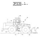
- a machine 10 is shown to have first and second frame members 12 and 14 respectively, that are mounted to one another for pivoting movement about a substantially vertical axis 15.
- the first or rear frame member provides support for a pair of wheels 16 (one shown in Fig. 1) that are positioned on opposite sides of the machine and an engine enclosure 18 housing an engine (not shown) that provides drive to the wheels 16.
- An operator station 20 is mounted to the rear frame 12 and houses a plurality of controls that are utilized to operate the machine.
- a steering control member such as a steering wheel assembly 22 that is normally supported by a console (not shown) that is in turn supported by the operator station.
- the second or front frame member 14 also supports a pair of wheels 24 (one shown in Fig. 1) that are positioned on opposite sides of the machine.
- a machine such as the wheel loader shown in Fig. 1, also provides drive from the engine to the front wheels 24.
- a work implement, such as bucket 26 is mounted on the front frame of the machine and is moveable in a substantially vertical plane to load and deposit material in a well known manner.
- the controls for operating the work implement are also located within the operator's station.
- a pair of fluid actuators, or hydraulic steering cylinders 28 are mounted between the frame members 12 and 14 on opposite sides of a longitudinal centerline 29 (Figs. 6-8) that runs the length of the machine.
- the steering cylinders may be actuated to pivot the front frame member with respect to the rear frame member on either side of the longitudinal centerline to provide steering of the machine.
- a first end portion 30 of the steering cylinder 28 is connected to the rear frame member 12 while a second end portion 32 is connected to the front frame portion as can best be seen in Fig. 2. While not shown in the drawings, the other steering cylinder is mounted on the opposite side of the machine in an identical manner.
- a fluid control means is provided to sequentially control the flow of pressurized fluid to the steering cylinders 28 so that one of the steering cylinders is extended while the other is retracted in a manner to be described in greater detail hereinafter.
- the fluid control means includes a control valve 36 that is mounted on the front frame 14 for movement therewith.
- the control valve 36 is shown as being a pilot valve that directs pilot pressure from an engine driven pump 38 to a steering valve 40.
- the steering valve 40 is in turn connected to the steering cylinders by a pair of conduits that extend from the respective head and rod ends of each steering cylinder in a well known manner.
- Operation of the steering valve in response to the pilot pressure will direct the flow of pressurized fluid from a main system pump (not shown) to the steering cylinders in a well known manner to cause the sequential operation thereof, i.e. extending one cylinder while retracting the other.
- the pilot system is shown schematically in Fig 3.
- the control valve 36 includes a directional control portion in the form of a rotary actuator 42, a pressure regulating valve 44 having a valve spool 46 movable in a rectilinear direction and an actuator 48 for mechanically imparting rectilinear movement of the valve spool 46 when the rotary actuator 42 is moved in either direction from a neutral position.
- the rotary actuator 42 includes a pair of control ports 50 and 52 connected to the steering valve 40, a drain port 54 connected to a tank 56 and an input passage 58.
- the rotary actuator 42 has a neutral position at which the control ports 50, 52 communicate with the drain port 54 and are blocked from the input passage 58.
- control valve has been described as being a pilot valve that communicates pilot pressure to the steering valve which in turn directs system pressure and flow to the respective steering cylinders. It is to be understood that the control valve could be in direct communication with the engine driven pump, and that either system would be acceptable without departing from the principles of the present invention. In either instance, the flow of the pressurized fluid (pilot or system pressure) is dictated by the rotary actuator 42 that is mounted for rotation within the control valve 36.
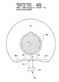
- the rotary actuator 42 has a shaft 68 that extends into the valve body 70 for rotation about an axis 72.
- a cam member 74 is positioned along the axis and is rotatable with the shaft 68.
- the cam member defines a plurality of operating surfaces that extend substantially along a horizontal plane as viewed in the drawings.
- the cam member 74 has a centrally disposed neutral portion 76 that is substantially centered beneath the axis 72 as viewed in the drawing.
- a first operating surface 78 is positioned on opposite sides of the neutral portion and is defined by a preselected radius that is relatively large to provide the first operating surface with a slight curvature.
- a second operating surface 80 is positioned adjacent each of the first operating surfaces 78 on opposing sides thereof.
- Each of the second operating surfaces 80 is defined a second preselected radius that is smaller than that of the first operating surface to thereby create a curvature having a greater amount of curvature than the first operating surface.
- An actuator 48 in the form of a cam follower is positioned beneath the cam member 74 and has a first end portion 84 that is engaged with the cam member and a second end portion 86 that is engaged with the pressure regulating valve 44 via a spring 87 (Fig. 3).
- the actuator 48 in the illustrated embodiment, moves in a linear direction and imparts rectilinear movement of the valve spool 46 as is described above. As the actuator is moved in a linear direction as a result of its contact with the cam member 74, it controls the amount of pressure that is directed to the steering valve, and thus the steering cylinders 28, as well as the rate at which the pressure of the fluid is increased.
- Movement of the rotary actuator 42 is imparted by a shaft assembly 88, a first end portion 90 of which is connected to the steering wheel 22 and a second end portion 92 of which is connected to the shaft 68 defined by the rotary actuator 42.
- the shaft assembly 88 includes a pair of constant velocity (CV) U-joints that are positioned in spaced relation to one another along the shaft assembly.
- the first end portion 90 of the shaft assembly is positioned in the operators station 20 and extends between the steering wheel 22 and a first CV joint 94.
- the second portion 92 of the shaft assembly is connected to the shaft 68 defined by the rotary actuator 42 by the a CV joint 96.
- the two CV joints are interconnected by a third shaft portion 98 that is telescopic to accommodate movement of the second CV joint 96 toward and away from the first CV joint 94 as the second frame 14 is articulated with respect to the first frame 12.
- the both of CV joints are shown to be of the type commonly known as a double Cardan U-joint. It is to be understood however, that another type of CV joint, such as one commonly known as a Rzeppa joint or any one of several commonly known CV joints, could be used in either one or both locations without departing from the intent of the present invention.
- the important function of the two CV joints is to impart substantially the same amount of rotation between the steering wheel 22 and the rotary actuator 42 regardless of the amount of articulation between the front and rear frames 14 and 12, respectively.
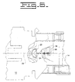
- a flat portion defined by the steering wheel is shown to be generally horizontally oriented and parallel to transverse portions of the front frame 14.
- the rotary actuator 42 is in the neutral position with the actuator 48 engaging the central portion 76 of the cam member 74.
- Fig. 7 it can be seen that the steering wheel 22 has been rotated in a counterclockwise direction.
- the amount of rotation is shown to be approximately 10 degrees as is illustrated by the angle "A" that is indicated by a line extending through the flat portion of the steering wheel and intersecting with a transverse line representing the non-rotated position of the steering wheel.
- the same amount of rotation is translated through the shaft assembly 88 to the rotary actuator 42.
- This rotates the cam 74, initially, in a counterclockwise direction, as viewed in Fig. 3, the same 10 degrees. This amount of rotation will cause the cam to engage the actuator 48 along the first operating surface 78.
- the regulating valve 44 When this condition exists, the regulating valve 44 is actuated and pressurized fluid is then directed to the input passage 58.
- the pressurized fluid will be communicated through flow path 64 to control port 52 while simultaneously communicating the control port 50 with the drain 54 through flow path 66.
- This directs pressurized fluid to the steering valve 40 which will in turn, control the flow fluid from the main system to the head end of one steering cylinder 28 to cause its extension and the rod end of the other steering cylinder to cause its retraction.
- the control valve 36 Since the steering wheel has been rotated an amount (10 degrees) that is within the first range of rotation, 0 to 13 degrees, the control valve 36 is operated in the first condition, directing pilot pressure to the steering valve 40 within a range of pressure that falls within 550 to 850 kPa.
- This first condition is initiated after the steering wheel is rotated more that 2 degrees whereupon the pressure climbs from 0 to 550 relatively quickly.
- the pilot pressure is typically communicated to the steering valve at a pressure that falls within the range of between 550 and 850 kPa.
- the rotary actuator is rotated an equivalent amount, which is shown to be approximately 25 degrees. With this amount of rotation, the actuator 48 will be placed into engagement with the second operating surface 80. In this condition, the actuator will move the regulating valve 44 to a position wherein pressurized fluid is directed to the steering valve 40 in the same manner previously described, however the range of pressure will fall within 850 to 1925 kPa. In doing so, the front frame is rotated with respect to the rear frame 12 an amount that is substantially equivalent to the 25 degree angle of the steering wheel. This position is indicated by angle "D" in Fig. 8.
- the fluid pressure in the second range R2 not only is greater than that of the first range R1 but it also increases at a faster rate over the given range of steering wheel rotation.
- the distance between the two CV joints will increase as the articulation of the frames continues. This variation in distance is accommodated by the telescopic third portion 98 of the shaft assembly 88. Also, since the distance between the second CV joint 96 and the vertical axis 15 is greater than the distance between the two CV joints 94 and 96, the angular relationship between the two CV joints will also change as the front frame pivots. Since the rotary actuator 42 is connected to the steering wheel by a shaft assembly that includes the two CV joints, and since the actuation of the rotary actuator is dictated by the steering wheel, relative rotation between the rotary actuator 42 and the control valve 36 will naturally occur as the front frame articulates.
- an articulated machine may be controlled in a very versatile manner.
- the steering corrections are normally relatively moderate, requiring small rotations of the steering wheel.
- These types of corrections will cause the control valve to operate in the first condition, providing steering corrections that are relatively smooth and subtle.
- the steering corrections require larger degrees of steering wheel rotation.
- the control valve will operate in its second condition and the steering corrections will be quicker providing increased frame acceleration which is very desirable when operating in confined quarters.
Landscapes
- Engineering & Computer Science (AREA)
- Chemical & Material Sciences (AREA)
- Combustion & Propulsion (AREA)
- Transportation (AREA)
- Mechanical Engineering (AREA)
- Power Steering Mechanism (AREA)
- Steering Control In Accordance With Driving Conditions (AREA)
Claims (20)
- Lenksystem zur Verwendung mit einer gelenkigen Maschine (10) mit ersten und zweiten Rahmengliedern (12, 14) angebracht aneinander zur Schwenkbewegung relativ zueinander ansprechend auf die Bewegung von mindestens einem dazwischen verbundenen Strömungsmittelbetätiger (28), wobei folgendes vorgesehen ist:ein Lenksteuerglied (22) ist drehbar auf dem ersten Rahmenglied (12) gelagert;ein Steuerventil (36) ist angebracht an dem zweiten Rahmenglied (14), wobei das Steuerventil einen Drehbetätiger (42) aufweist, und bei Drehung des Lenksteuerglieds (22) betätigbar ist, um die Bewegung des Strömungsmittelbetätigers (28) selektiv zu steuern;eine Wellenanordnung (88) mit ersten und zweiten Endteilen (90, 92), wobei der erste Endteil (90) mit dem Lenksteuerglied (22) verbunden ist, und wobei der Endteil (92) mit dem Drehbetätiger (42) verbunden ist, dadurch gekennzeichnet, dassein Paar Konstantgeschwindigkeits-U-Verbindungen (94, 96) in Abstandsbeziehung angeordnet ist zwischen den ersten und zweiten Endteilen (90, 92) der Wellenanordnung (88); und das erwähnte Steuerventil (36) in einem ersten Zustand betätigbar ist, wo unter Druck stehendes Strömungsmittel zu dem Strömungsmittelbetätiger (28) geleitet wird, und zwar innerhalb eines ersten vorgewählten Bereiches (R1) des Drucks bei anfänglicher Verdrängung des Lenksteuerglieds (22) innerhalb eines ersten vorgewählten Drehbereichs, und wobei das Steuerventil (36) in einem zweiten Zustand betätigbar ist, wo unter Druck stehendes Strömungsmittel zu dem Strömungsmittelbetätiger (28) geleitet wird, und zwar innerhalb eines zweiten vorgewählten Bereichs (R2) des Druckes bei anfänglicher Verdrängung des Lenksteuergliedes (22) innerhalb eines zweiten vorgewählten Bereiches der Drehung.
- Lenksystem nach Anspruch 1, wobei das Paar von Konstantgeschwindgkeits-U-Verbindungen (94, 96) geeignet ist, um die Winkeländerung zwischen den zwei Rahmengliedern (12, 14) aufzunehmen, wenn sie bezüglich einander bewegt werden, um ein Drehverhältnis von annähernd 1 : 1 zwischen den ersten und zweiten Endeilen (90, 92) der Wellenanordnung (88) aufrechtzuerhalten.
- Lenksystem nach Anspruch 1 oder 2, wobei das Lenksteuerglied (22) ein Lenkrad ist.
- Lenksystem nach Anspruch 1, wobei das Steuerventil (36) ein Pilotoder Vorsteuerventil ist, das die Verbindung von unter Druck stehendem Strömungsmittel mit einem Lenkventil (40) vorsieht, und zwar zur Steuerung der Bewegung des Strömungsmittelbetätigers (28).
- Lenksystem nach Anspruch 4, wobei das Vorsteuerventil (36) in einem ersten Zustand arbeitet, wo die Ausgangsgröße des unter Druck stehenden Strömungsmittels verbunden mit dem Lenkventil (40) innerhalb eines ersten vorgewählten Bereichs des Drucks gehalten wird, und zwar ansprechend auf einen ersten vorgewählten Drehbereich des Lenksteuerglieds (22), und wobei das Vorsteuerventil (36) in einem zweiten Zustand arbeitet, wo die Ausgangsgröße des unter Druck stehenden Strömungsmittels verbunden mit dem Lenkventil (40) innerhalb eines zweiten vorgewählten Bereichs (R2) des Drucks gehalten wird, während einer zweiten vorgewählten Größe der Drehung des Lenksteuerglieds (22), wobei der erwähnte zweite Druckbereich (R2) in seiner Größe und Vergrößerungsanstiegsrate größer ist als der erwähnte erste Druckbereich (R1).
- Lenksystem nach Anspruch 4 oder 5, wobei das Vorsteuerventil (36) einen Drehbetätiger (42) aufweist, mit einem Nockenteil (74) und einem Linearbetätiger (48) positioniert zum Eingriff mit dem Nockenteil (74) und geeignet zur Steuerung der Menge von unter Druck stehendem Strömungsmittel die zu dem Lenkventil (40) geleitet wird.
- Lenksystem nach Anspruch 6, wobei das Nockenglied (74) einen Mittelteil (76) definiert, ferner eine erste Betriebsoberfläche (78) an entgegengesetzten Seiten des Mittelteils (76) und eine zweite Betriebsoberfläche (80) positioniert benachbart zur ersten Betriebsoberfläche (78) an einer entgegengesetzt liegenden Seite davon von dem Mittelteil (76), wobei der Eingriff des erwähnten Linearbetätigers (48) mit der einen oder anderen der entsprechenden ersten Betriebsoberflächen (78) den Betrieb des Pilotventils (36) in dem ersten Zustand bewirkt und den Eingriff des Linearbetätigers (48) mit der einen oder anderen der zweiten Betriebsoberflächen (80) den Betrieb des Pilotoder Vorsteuerventils (36) in dem zweiten Zustand hervorruft.
- Lenksystem nach Anspruch 7, wobei die ersten und zweiten Betriebsoberflächen (78, 80) sich von dem Mittelteil (76) in einer allgemeinen horizontalen Ebene wegerstreckt, wobei die ersten Betriebsoberflächen (78), durch einen Radius einer ersten vorgewählten Größe definiert sind, und wobei die zweite Betriebsoberfläche (80) durch einen Radius einer zweiten vorgewählten Größe definiert ist, die kleiner ist als die erste Betriebsoberfläche (78) um eine Oberfläche zu schaffen, die eine größere Krümmung besitzt als die erste Betriebsoberfläche (78).
- Lenksystem nach Anspruch 1, wobei eine erste (94) des Paares von Konstantgeschwindgkeits-U-Verbindungen (94, 96) verbünden ist mit dem Lenkrad (22), und zwar durch einen ersten Teil (90) der Schaftanordnung (88), und eine zweite (96) des Paares von Konstantgeschwindgkeits-U-Verbindungen (94, 96) verbunden ist mit dem Drehbetätiger (42), wobei die Schaftanordnung (88) geeignet ist, um eine Drehgröße zu dem Drehbetätiger (42) zu übertragen, die im wesentlichen gleich der Drehgröße des Lenkrades (22) ist, und zwar über den gesamten Bereich der Relativbewegung zwischen den ersten und zweiten Rahmengliedern (12, 14) hinweg.
- Lenksystem nach Anspruch 1, wobei der Drehbetätiger (42) eine Neutralposition besitzt, wo kein unter Druck stehendes Strömungsmittel zu dem Strömungsmittelbetätiger (28) geleitet wird, wobei ferner der Drehbetätiger (42) aus seiner Neutralposition wegbewegbar ist infolge einer Dreheingangsgröße vom Lenkrad (22) um unter Druck stehendes Strömungsmittel zu dem Strömungsmittelbetätiger (28) zu leiten, um das zweite Rahmenglied (14) bezüglich des ersten Rahmengliedes (12) zu bewegen, und wobei die Bewegung des zweiten Rahmengliedes (14) bezüglich des ersten Rahmengliedes (12) bewirkt, dass der Drehbetätiger (42) sich in einer Richtung entgegengesetzt zu der der Lenkrad (22) Eingangsgröße verdreht, zurück zu seiner Neutralposition um allmählich den Strömungsmittelfluß zu dem Strömungsmittelbetätiger (28) zu reduzieren und schließlich zu eliminieren, dann wenn der Gelenkverbindungswinkel zwischen den ersten und zweiten Rahmengliedern (12, 14) im wesentlichen gleich dem Drehwinkel des Lenkrads (22) ist bei Nichtvorhandensein irgendeiner zusätzlichen Drehung des Lenkrades (22).
- Lenksystem nach Anspruch 10, wobei der Drehbetätiger (42) einen Nockenteil (74) aufweist, mit einem Mittelteil (76) der die Neutralposition des Drehbetätigers (42) definiert, und wobei ferner ein Paar von ersten Betätigungsoberflächen (78) benachbart zum Mittelteil (76) auf entgegengesetzten Seiten davon vorgesehen ist, und schließlich ein zweites Paar von Betriebsoder Betätigungsoberflächen (80) positioniert benachbart zu den ersten Betätigungs- oder Betriebsoberflächen (78) auf entgegengesetzten Seiten davon vom Mittelteil (76).
- Lenksystem nach Anspruch 11, wobei das Vorsteuerventil (36) einen Betätiger (48) aufweist, mit einem ersten Endteil (84) geeignet zum Eingriff mit dem Nockenteil (74) und einem zweiten Endteil (86) geeignet zum Eingriff mit einem Druckregulierventil (44) zur Steuerung der mit dem Lenkventil (40) verbundenen Druckgröße.
- Lenksystem nach Anspruch 11, wobei der Betätiger (48) in Eingriff bringbar ist mit dem Mittelteil (76) des Nockenteils (74) wenn der Drehbetätiger (42) sich in seiner Neutralposition befindet, mit der ersten Betriebsoberfläche (78) wenn das Steuerventil (36) in seinem ersten Zustand betrieben wird, und mit der zweiten Betriebsoberfläche (80) wenn das Steuerventil in seinem zweiten Zustand betrieben wird.
- Lenksystem nach Anspruch 4, wobei der erste Betriebszustand des Steuerventils (36) die Verbindung des Pilot- oder Vorsteuerdrucks zwischen Steuerventil (36) und Lenkventil (40) umfaßt, und zwar innerhalb eines Bereichs (R1) des Drucks der annähert zwischen 0 und 850 kPa liegt, während des ersten vorgewählten Bereichs der Lenkrad (22) Verdrehung, die annähernd zwischen 0 und 13 Grad Drehung liegt, und wobei der zweite Zustand des Betriebes des Steuerventils (36) die Verbindung des Vorsteuerdruckes aufweist, und zwar zwischen Steuerventil (36) und Lenkventil (40) innerhalb eines Bereichs (R2) von annähernd 850 bis 1925 kPa während des zweiten vorgewählten Bereichs der Lenkrad (22) Drehung der annähernd zwischen 14 und 35 Grad Drehung liegt.
- Lenksystem nach Anspruch 14, wobei die Anstiegsrate des Strömungsmitteldruckes verbunden oder liegend zwischen dem Steuerventil (36) und dem Lenkventil (40) annähernd 850 kPa über den ersten Bereich der Drehung des Lenkrades (22) ist, und annähernd 1075 kPa über den zweiten Bereich der Drehung des Lenkrades (22).
- Lenksystem nach einem der vorhergehenden Ansprüche, wobei das erste Rahmenglied (12) und das zweite Rahmenglied (14) bezüglich einander um eine im wesentlichen vertikal orientierte Achse (15) sich verschwenken.
- Lenksystem nach Anspruch 16, wobei ein Paar von Strömungsmittelbetätigern (28) verbunden ist, zwischen den ersten und zweiten Rahmengliedern (12, 14), und zwar positioniert auf entgegengesetzten Seiten der Achse (15).
- Lenksystem nach Anspruch 1, wobei der Druck des Strömungsmittels verbunden ist zwischen dem Steuerventil (36) und einem Lenkventil (40) in einer Art und Weise, wo der Druck annähernd zwischen 0 und 850 kPa während des Betriebes des Steuerventils (36) im ersten Zustand ansteigt und annähernd zwischen 850 und 1925 kPa ansteigt während des Betriebs im zweiten Zustand des Steuerventils (36).
- Lenksystem nach Anspruch 16, wobei die erste Konstantgeschwindigkeits-U-Verbindung (94) am ersten Rahmenglied (12) positioniert ist mit einem festen Abstand von der Schwenkachse (15), und wobei die zweite Konstantgeschwindigkeits-U-Verbindung (96) benachbart zum Steuerventil (36) positioniert ist, angebracht auf dem zweiten Rahmenglied (14) mit einem Abstand von der Schwenkachse (15), der sich verändert, wenn der zweite Rahmen (14) sich bezüglich des ersten Rahmens (12) verdreht, wobei die ersten und zweiten U-Verbindungen (94, 96) durch einen Teil (98) der Wellenanordnung (88) verbunden sind, der teleskopartig ausgebildet ist, um die Bewegung der zweiten U-Verbindung (96) in einer Richtung zu der ersten U-Verbindung (94) hin und von dieser weg ermöglicht wird, und zwar ansprechend auf die Relativbewegung zwischen den ersten und zweiten Rahmengliedern (12, 14).
- Lenksystem nach Anspruch 19, wobei die ersten und zweiten Konstantgeschwindigkeits-U-Verbindungen (94, 96) Doppel-Kardan-U-Verbindungen sind.
Applications Claiming Priority (3)
| Application Number | Priority Date | Filing Date | Title |
|---|---|---|---|
| US5870597P | 1997-09-12 | 1997-09-12 | |
| US58705P | 1997-09-12 | ||
| PCT/US1998/018156 WO1999014100A1 (en) | 1997-09-12 | 1998-09-02 | Steering system for an articulated machine |
Publications (2)
| Publication Number | Publication Date |
|---|---|
| EP0938424A1 EP0938424A1 (de) | 1999-09-01 |
| EP0938424B1 true EP0938424B1 (de) | 2002-05-02 |
Family
ID=22018412
Family Applications (1)
| Application Number | Title | Priority Date | Filing Date |
|---|---|---|---|
| EP98942348A Expired - Lifetime EP0938424B1 (de) | 1997-09-12 | 1998-09-02 | Lenkung für ein fahrzeug mit knickrahmen |
Country Status (5)
| Country | Link |
|---|---|
| US (1) | US6158544A (de) |
| EP (1) | EP0938424B1 (de) |
| JP (1) | JP4300277B2 (de) |
| DE (1) | DE69805157T2 (de) |
| WO (1) | WO1999014100A1 (de) |
Families Citing this family (4)
| Publication number | Priority date | Publication date | Assignee | Title |
|---|---|---|---|---|
| US7610989B2 (en) * | 2002-05-29 | 2009-11-03 | Volvo Construction Equipment Ab | Control system and a vehicle comprising the control system |
| US7798282B2 (en) * | 2008-03-04 | 2010-09-21 | Ford Global Technologies, Llc | Power assisted steering system |
| US8002074B2 (en) * | 2009-07-27 | 2011-08-23 | Roose Mfg. Company | Center-pivot steering articulated vehicle |
| WO2018049475A1 (en) | 2016-09-15 | 2018-03-22 | Terex Australia Pty Ltd | Crane counterweight and suspension |
Family Cites Families (19)
| Publication number | Priority date | Publication date | Assignee | Title |
|---|---|---|---|---|
| FR87497E (fr) * | 1960-11-21 | 1966-05-06 | Citroen Sa Andre | Perfectionnements aux dispositifs de direction asservie pour véhicule automobile |
| US3340949A (en) * | 1966-06-23 | 1967-09-12 | Eaton Yale & Towne | Variable rate steering for articulated vehicle |
| US3554312A (en) * | 1967-09-01 | 1971-01-12 | Westinghouse Air Brake Co | Vehicle steering system |
| US4057158A (en) * | 1976-06-01 | 1977-11-08 | Igor Lissy | Aircraft towing vehicle |
| DE2903624A1 (de) * | 1979-01-31 | 1980-08-14 | Zahnradfabrik Friedrichshafen | Hydraulische lenkeinrichtung fuer fahrzeuge mit einem knickgelenk |
| US4700794A (en) * | 1986-07-14 | 1987-10-20 | Caterpillar Inc. | Vehicle steering apparatus |
| DE3821700A1 (de) * | 1988-06-28 | 1990-01-04 | Deere & Co | Steuervorrichtung fuer mindestens ein ventil |
| US5085245A (en) * | 1989-04-21 | 1992-02-04 | Remote Controls, Inc. | Flow control valve cartridge |
| US4955442A (en) * | 1989-05-16 | 1990-09-11 | Caterpillar Inc. | Steering mechanism for a vehicle |
| US5042314A (en) * | 1989-11-02 | 1991-08-27 | Caterpillar Inc. | Steering and transmission shifting control mechanism |
| US5366316A (en) * | 1992-06-02 | 1994-11-22 | General Motors Corporation | Intermediate steering shaft assembly and method |
| US5411110A (en) * | 1993-03-09 | 1995-05-02 | New Venture Gear, Inc. | Power transfer system for a four-wheel drive vehicle |
| US5365803A (en) * | 1993-07-13 | 1994-11-22 | Caterpillar Inc. | Steering and transmission shifting control device |
| DE4440232A1 (de) * | 1993-11-23 | 1995-05-24 | Barksdale Inc | Fluidventil |
| US5489005A (en) * | 1994-11-23 | 1996-02-06 | Caterpillar Inc. | Electro-hydraulic steering system |
| US5579863A (en) * | 1995-04-10 | 1996-12-03 | Caterpillar Inc. | Steering system for an articulated machine |
| US5520262A (en) * | 1995-04-28 | 1996-05-28 | Caterpillar Inc. | Electrohydraulic steering system |
| US5979504A (en) * | 1996-05-02 | 1999-11-09 | Caterpillar Inc. | Rotary control valve |
| US5752578A (en) * | 1996-05-07 | 1998-05-19 | Caterpillar Inc. | Control apparatus |
-
1998
- 1998-09-02 DE DE69805157T patent/DE69805157T2/de not_active Expired - Fee Related
- 1998-09-02 JP JP51696699A patent/JP4300277B2/ja not_active Expired - Fee Related
- 1998-09-02 WO PCT/US1998/018156 patent/WO1999014100A1/en not_active Ceased
- 1998-09-02 EP EP98942348A patent/EP0938424B1/de not_active Expired - Lifetime
- 1998-09-09 US US09/150,272 patent/US6158544A/en not_active Expired - Lifetime
Also Published As
| Publication number | Publication date |
|---|---|
| EP0938424A1 (de) | 1999-09-01 |
| DE69805157T2 (de) | 2002-12-19 |
| JP4300277B2 (ja) | 2009-07-22 |
| JP2001507310A (ja) | 2001-06-05 |
| US6158544A (en) | 2000-12-12 |
| DE69805157D1 (de) | 2002-06-06 |
| WO1999014100A1 (en) | 1999-03-25 |
Similar Documents
| Publication | Publication Date | Title |
|---|---|---|
| US5899292A (en) | Hydraulic drive and steering systems for a vehicle | |
| EP0737612B1 (de) | Lenkung für ein Knickrahmenfahrzeug | |
| US4565257A (en) | Multi-mode steering system | |
| US5995893A (en) | Device for controlling the operation of power excavators | |
| US6152239A (en) | Ergonomic electronic hand control for a motor grader | |
| USH1822H (en) | Miniature joystick mounted on a joystick | |
| US5520262A (en) | Electrohydraulic steering system | |
| US5413452A (en) | Hydraulic system for a backhoe apparatus | |
| CA2606350A1 (en) | Universal linkage assembly for a power machine | |
| WO2023286444A1 (ja) | 作業機械、及び作業機械を制御するための方法 | |
| US5692541A (en) | Hydraulic joystick | |
| EP0438435B1 (de) | Hydraulisches lenkungssystem | |
| US20100051376A1 (en) | Bending Construction Vehicle | |
| EP0938424B1 (de) | Lenkung für ein fahrzeug mit knickrahmen | |
| US3380547A (en) | Steering system | |
| US20020070071A1 (en) | Electro-hydraulic load sense on a power machine | |
| US6041673A (en) | Dual function throttle control system for heavy construction equipment machines | |
| USH1851H (en) | Motor grader having dual steering mechanisms | |
| CA2288572A1 (en) | Motor grader steerable by a joystick and a steering wheel | |
| AU2021102514B4 (en) | Hydraulic cylinder with specific performance dimensions | |
| AU2021102521B4 (en) | Hydraulic cylinder with specific performance dimensions | |
| AU2021102518B4 (en) | Hydraulic cylinder with specific performance dimensions | |
| AU2021102515B4 (en) | Hydraulic cylinder with specific performance dimensions | |
| AU2021102522B4 (en) | Hydraulic cylinder with specific performance dimensions | |
| EP4159592A1 (de) | Lenkungssteuerungsvorrichtung für arbeitsfahrzeug |
Legal Events
| Date | Code | Title | Description |
|---|---|---|---|
| PUAI | Public reference made under article 153(3) epc to a published international application that has entered the european phase |
Free format text: ORIGINAL CODE: 0009012 |
|
| 17P | Request for examination filed |
Effective date: 19990507 |
|
| AK | Designated contracting states |
Kind code of ref document: A1 Designated state(s): DE SE |
|
| 17Q | First examination report despatched |
Effective date: 20000824 |
|
| GRAG | Despatch of communication of intention to grant |
Free format text: ORIGINAL CODE: EPIDOS AGRA |
|
| GRAG | Despatch of communication of intention to grant |
Free format text: ORIGINAL CODE: EPIDOS AGRA |
|
| GRAH | Despatch of communication of intention to grant a patent |
Free format text: ORIGINAL CODE: EPIDOS IGRA |
|
| GRAH | Despatch of communication of intention to grant a patent |
Free format text: ORIGINAL CODE: EPIDOS IGRA |
|
| GRAA | (expected) grant |
Free format text: ORIGINAL CODE: 0009210 |
|
| AK | Designated contracting states |
Kind code of ref document: B1 Designated state(s): DE SE |
|
| REF | Corresponds to: |
Ref document number: 69805157 Country of ref document: DE Date of ref document: 20020606 |
|
| PLBE | No opposition filed within time limit |
Free format text: ORIGINAL CODE: 0009261 |
|
| STAA | Information on the status of an ep patent application or granted ep patent |
Free format text: STATUS: NO OPPOSITION FILED WITHIN TIME LIMIT |
|
| 26N | No opposition filed |
Effective date: 20030204 |
|
| PGFP | Annual fee paid to national office [announced via postgrant information from national office to epo] |
Ref country code: DE Payment date: 20060929 Year of fee payment: 9 |
|
| PGFP | Annual fee paid to national office [announced via postgrant information from national office to epo] |
Ref country code: SE Payment date: 20060908 Year of fee payment: 9 |
|
| PG25 | Lapsed in a contracting state [announced via postgrant information from national office to epo] |
Ref country code: SE Free format text: LAPSE BECAUSE OF NON-PAYMENT OF DUE FEES Effective date: 20070903 |
|
| EUG | Se: european patent has lapsed | ||
| PG25 | Lapsed in a contracting state [announced via postgrant information from national office to epo] |
Ref country code: DE Free format text: LAPSE BECAUSE OF NON-PAYMENT OF DUE FEES Effective date: 20080401 |