EP0938424B1 - Systeme de direction pour machine articulee - Google Patents
Systeme de direction pour machine articulee Download PDFInfo
- Publication number
- EP0938424B1 EP0938424B1 EP98942348A EP98942348A EP0938424B1 EP 0938424 B1 EP0938424 B1 EP 0938424B1 EP 98942348 A EP98942348 A EP 98942348A EP 98942348 A EP98942348 A EP 98942348A EP 0938424 B1 EP0938424 B1 EP 0938424B1
- Authority
- EP
- European Patent Office
- Prior art keywords
- steering
- valve
- rotation
- set forth
- steering system
- Prior art date
- Legal status (The legal status is an assumption and is not a legal conclusion. Google has not performed a legal analysis and makes no representation as to the accuracy of the status listed.)
- Expired - Lifetime
Links
- 239000012530 fluid Substances 0.000 claims description 40
- 230000007935 neutral effect Effects 0.000 claims description 13
- 230000004044 response Effects 0.000 claims description 7
- 230000001105 regulatory effect Effects 0.000 claims description 5
- 230000008859 change Effects 0.000 claims description 3
- 230000001276 controlling effect Effects 0.000 claims 1
- 238000012937 correction Methods 0.000 description 5
- 230000005540 biological transmission Effects 0.000 description 4
- 239000000463 material Substances 0.000 description 4
- 230000008901 benefit Effects 0.000 description 2
- 238000010348 incorporation Methods 0.000 description 2
- 230000000977 initiatory effect Effects 0.000 description 2
- 230000001133 acceleration Effects 0.000 description 1
- 230000001419 dependent effect Effects 0.000 description 1
- 230000007246 mechanism Effects 0.000 description 1
Images




Classifications
-
- B—PERFORMING OPERATIONS; TRANSPORTING
- B62—LAND VEHICLES FOR TRAVELLING OTHERWISE THAN ON RAILS
- B62D—MOTOR VEHICLES; TRAILERS
- B62D12/00—Steering specially adapted for vehicles operating in tandem or having pivotally connected frames
-
- B—PERFORMING OPERATIONS; TRANSPORTING
- B62—LAND VEHICLES FOR TRAVELLING OTHERWISE THAN ON RAILS
- B62D—MOTOR VEHICLES; TRAILERS
- B62D1/00—Steering controls, i.e. means for initiating a change of direction of the vehicle
- B62D1/02—Steering controls, i.e. means for initiating a change of direction of the vehicle vehicle-mounted
- B62D1/16—Steering columns
-
- B—PERFORMING OPERATIONS; TRANSPORTING
- B62—LAND VEHICLES FOR TRAVELLING OTHERWISE THAN ON RAILS
- B62D—MOTOR VEHICLES; TRAILERS
- B62D1/00—Steering controls, i.e. means for initiating a change of direction of the vehicle
- B62D1/02—Steering controls, i.e. means for initiating a change of direction of the vehicle vehicle-mounted
- B62D1/16—Steering columns
- B62D1/20—Connecting steering column to steering gear
Definitions
- This invention relates generally to a steering system for an articulated machine and more particularly to a steering system that provides a mechanical feedback to the steering wheel.
- a steering mechanism that includes a pair of hydraulic cylinders that are connected between the front and rear frames of the machine on opposing sides of an articulation point.
- the steering cylinders may be selectively actuated to extend one and retract the other to pivot the front frame with respect to the rear frame to affect a steering maneuver.
- HMU hand metering unit
- the response of the machine is such that initial movements of the steering wheel from its neutral position result in smaller amounts of response at the control valve than what is experienced when the machine is articulated.
- This has been known to provide a steering system that is much less “jerky” during “roading” operations and is more responsive with less amounts of steering wheel rotation during truck loading operations. While this has been quite successful in the operation of larger wheel loaders, the mechanical modulation is not quite as effective or comfortable for the individual operating smaller wheel loaders that may be operated on highways at higher speeds.
- the present invention is directed to overcoming one or more of the problems as set forth above.
- a steering system adapted for use with an articulated machine comprises the features set forth in claim 1. Preferred embodiments of the present invention may be gathered from the dependent claims.
- the fluid actuators that extend between the frame members of an articulated machine may be controlled by a steering wheel that requires a relatively small amount of overall rotation between its maximum positions.
- the connection between the steering wheel and the actuation within the control valve permit modulation of the pressurized fluid to the steering cylinders such that only a small amount of pressurized fluid is directed to the steering cylinders during the initial portion of rotation of the steering wheel to allow for subtle changes in articulation. This is very conducive for operation under relatively high speeds.
- the modulation of the control valve upon the greater portions of steering wheel rotation permits the application of increased flow of pressurized fluid to the steering cylinders to achieve greater movement thereof when operating the machine in confined loading situations.
- This steering system ultimately provides control for the machine that is extremely versatile in all phases of machine operation and yet reduces the fatigue normally experienced by a machine operator.
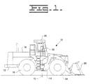
- a machine 10 is shown to have first and second frame members 12 and 14 respectively, that are mounted to one another for pivoting movement about a substantially vertical axis 15.
- the first or rear frame member provides support for a pair of wheels 16 (one shown in Fig. 1) that are positioned on opposite sides of the machine and an engine enclosure 18 housing an engine (not shown) that provides drive to the wheels 16.
- An operator station 20 is mounted to the rear frame 12 and houses a plurality of controls that are utilized to operate the machine.
- a steering control member such as a steering wheel assembly 22 that is normally supported by a console (not shown) that is in turn supported by the operator station.
- the second or front frame member 14 also supports a pair of wheels 24 (one shown in Fig. 1) that are positioned on opposite sides of the machine.
- a machine such as the wheel loader shown in Fig. 1, also provides drive from the engine to the front wheels 24.
- a work implement, such as bucket 26 is mounted on the front frame of the machine and is moveable in a substantially vertical plane to load and deposit material in a well known manner.
- the controls for operating the work implement are also located within the operator's station.
- a pair of fluid actuators, or hydraulic steering cylinders 28 are mounted between the frame members 12 and 14 on opposite sides of a longitudinal centerline 29 (Figs. 6-8) that runs the length of the machine.
- the steering cylinders may be actuated to pivot the front frame member with respect to the rear frame member on either side of the longitudinal centerline to provide steering of the machine.
- a first end portion 30 of the steering cylinder 28 is connected to the rear frame member 12 while a second end portion 32 is connected to the front frame portion as can best be seen in Fig. 2. While not shown in the drawings, the other steering cylinder is mounted on the opposite side of the machine in an identical manner.
- a fluid control means is provided to sequentially control the flow of pressurized fluid to the steering cylinders 28 so that one of the steering cylinders is extended while the other is retracted in a manner to be described in greater detail hereinafter.
- the fluid control means includes a control valve 36 that is mounted on the front frame 14 for movement therewith.
- the control valve 36 is shown as being a pilot valve that directs pilot pressure from an engine driven pump 38 to a steering valve 40.
- the steering valve 40 is in turn connected to the steering cylinders by a pair of conduits that extend from the respective head and rod ends of each steering cylinder in a well known manner.
- Operation of the steering valve in response to the pilot pressure will direct the flow of pressurized fluid from a main system pump (not shown) to the steering cylinders in a well known manner to cause the sequential operation thereof, i.e. extending one cylinder while retracting the other.
- the pilot system is shown schematically in Fig 3.
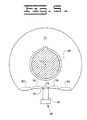
- the control valve 36 includes a directional control portion in the form of a rotary actuator 42, a pressure regulating valve 44 having a valve spool 46 movable in a rectilinear direction and an actuator 48 for mechanically imparting rectilinear movement of the valve spool 46 when the rotary actuator 42 is moved in either direction from a neutral position.
- the rotary actuator 42 includes a pair of control ports 50 and 52 connected to the steering valve 40, a drain port 54 connected to a tank 56 and an input passage 58.
- the rotary actuator 42 has a neutral position at which the control ports 50, 52 communicate with the drain port 54 and are blocked from the input passage 58.
- control valve has been described as being a pilot valve that communicates pilot pressure to the steering valve which in turn directs system pressure and flow to the respective steering cylinders. It is to be understood that the control valve could be in direct communication with the engine driven pump, and that either system would be acceptable without departing from the principles of the present invention. In either instance, the flow of the pressurized fluid (pilot or system pressure) is dictated by the rotary actuator 42 that is mounted for rotation within the control valve 36.
- the rotary actuator 42 has a shaft 68 that extends into the valve body 70 for rotation about an axis 72.
- a cam member 74 is positioned along the axis and is rotatable with the shaft 68.
- the cam member defines a plurality of operating surfaces that extend substantially along a horizontal plane as viewed in the drawings.
- the cam member 74 has a centrally disposed neutral portion 76 that is substantially centered beneath the axis 72 as viewed in the drawing.
- a first operating surface 78 is positioned on opposite sides of the neutral portion and is defined by a preselected radius that is relatively large to provide the first operating surface with a slight curvature.
- a second operating surface 80 is positioned adjacent each of the first operating surfaces 78 on opposing sides thereof.
- Each of the second operating surfaces 80 is defined a second preselected radius that is smaller than that of the first operating surface to thereby create a curvature having a greater amount of curvature than the first operating surface.
- An actuator 48 in the form of a cam follower is positioned beneath the cam member 74 and has a first end portion 84 that is engaged with the cam member and a second end portion 86 that is engaged with the pressure regulating valve 44 via a spring 87 (Fig. 3).
- the actuator 48 in the illustrated embodiment, moves in a linear direction and imparts rectilinear movement of the valve spool 46 as is described above. As the actuator is moved in a linear direction as a result of its contact with the cam member 74, it controls the amount of pressure that is directed to the steering valve, and thus the steering cylinders 28, as well as the rate at which the pressure of the fluid is increased.
- Movement of the rotary actuator 42 is imparted by a shaft assembly 88, a first end portion 90 of which is connected to the steering wheel 22 and a second end portion 92 of which is connected to the shaft 68 defined by the rotary actuator 42.
- the shaft assembly 88 includes a pair of constant velocity (CV) U-joints that are positioned in spaced relation to one another along the shaft assembly.
- the first end portion 90 of the shaft assembly is positioned in the operators station 20 and extends between the steering wheel 22 and a first CV joint 94.
- the second portion 92 of the shaft assembly is connected to the shaft 68 defined by the rotary actuator 42 by the a CV joint 96.
- the two CV joints are interconnected by a third shaft portion 98 that is telescopic to accommodate movement of the second CV joint 96 toward and away from the first CV joint 94 as the second frame 14 is articulated with respect to the first frame 12.
- the both of CV joints are shown to be of the type commonly known as a double Cardan U-joint. It is to be understood however, that another type of CV joint, such as one commonly known as a Rzeppa joint or any one of several commonly known CV joints, could be used in either one or both locations without departing from the intent of the present invention.
- the important function of the two CV joints is to impart substantially the same amount of rotation between the steering wheel 22 and the rotary actuator 42 regardless of the amount of articulation between the front and rear frames 14 and 12, respectively.
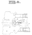
- a flat portion defined by the steering wheel is shown to be generally horizontally oriented and parallel to transverse portions of the front frame 14.
- the rotary actuator 42 is in the neutral position with the actuator 48 engaging the central portion 76 of the cam member 74.
- Fig. 7 it can be seen that the steering wheel 22 has been rotated in a counterclockwise direction.
- the amount of rotation is shown to be approximately 10 degrees as is illustrated by the angle "A" that is indicated by a line extending through the flat portion of the steering wheel and intersecting with a transverse line representing the non-rotated position of the steering wheel.
- the same amount of rotation is translated through the shaft assembly 88 to the rotary actuator 42.
- This rotates the cam 74, initially, in a counterclockwise direction, as viewed in Fig. 3, the same 10 degrees. This amount of rotation will cause the cam to engage the actuator 48 along the first operating surface 78.
- the regulating valve 44 When this condition exists, the regulating valve 44 is actuated and pressurized fluid is then directed to the input passage 58.
- the pressurized fluid will be communicated through flow path 64 to control port 52 while simultaneously communicating the control port 50 with the drain 54 through flow path 66.
- This directs pressurized fluid to the steering valve 40 which will in turn, control the flow fluid from the main system to the head end of one steering cylinder 28 to cause its extension and the rod end of the other steering cylinder to cause its retraction.
- the control valve 36 Since the steering wheel has been rotated an amount (10 degrees) that is within the first range of rotation, 0 to 13 degrees, the control valve 36 is operated in the first condition, directing pilot pressure to the steering valve 40 within a range of pressure that falls within 550 to 850 kPa.
- This first condition is initiated after the steering wheel is rotated more that 2 degrees whereupon the pressure climbs from 0 to 550 relatively quickly.
- the pilot pressure is typically communicated to the steering valve at a pressure that falls within the range of between 550 and 850 kPa.
- the rotary actuator is rotated an equivalent amount, which is shown to be approximately 25 degrees. With this amount of rotation, the actuator 48 will be placed into engagement with the second operating surface 80. In this condition, the actuator will move the regulating valve 44 to a position wherein pressurized fluid is directed to the steering valve 40 in the same manner previously described, however the range of pressure will fall within 850 to 1925 kPa. In doing so, the front frame is rotated with respect to the rear frame 12 an amount that is substantially equivalent to the 25 degree angle of the steering wheel. This position is indicated by angle "D" in Fig. 8.
- the fluid pressure in the second range R2 not only is greater than that of the first range R1 but it also increases at a faster rate over the given range of steering wheel rotation.
- the distance between the two CV joints will increase as the articulation of the frames continues. This variation in distance is accommodated by the telescopic third portion 98 of the shaft assembly 88. Also, since the distance between the second CV joint 96 and the vertical axis 15 is greater than the distance between the two CV joints 94 and 96, the angular relationship between the two CV joints will also change as the front frame pivots. Since the rotary actuator 42 is connected to the steering wheel by a shaft assembly that includes the two CV joints, and since the actuation of the rotary actuator is dictated by the steering wheel, relative rotation between the rotary actuator 42 and the control valve 36 will naturally occur as the front frame articulates.
- an articulated machine may be controlled in a very versatile manner.
- the steering corrections are normally relatively moderate, requiring small rotations of the steering wheel.
- These types of corrections will cause the control valve to operate in the first condition, providing steering corrections that are relatively smooth and subtle.
- the steering corrections require larger degrees of steering wheel rotation.
- the control valve will operate in its second condition and the steering corrections will be quicker providing increased frame acceleration which is very desirable when operating in confined quarters.
Landscapes
- Engineering & Computer Science (AREA)
- Chemical & Material Sciences (AREA)
- Combustion & Propulsion (AREA)
- Transportation (AREA)
- Mechanical Engineering (AREA)
- Power Steering Mechanism (AREA)
- Steering Control In Accordance With Driving Conditions (AREA)
Claims (20)
- Système de direction adapté à une machine articulée (10) ayant des premier et second éléments de châssis (12, 14) montés pour pouvoir pivoter l'un par rapport à l'autre en réponse au déplacement d'au moins un actionneur à fluide (28) connecté entre eux, comprenant :caractérisé en ce que :un élément de commande de direction (22) monté à rotation sur le premier élément de châssis (12) ;une vanne de commande (36) montée sur le second élément de châssis (14), la vanne de commande comprenant un actionneur tournant (42) et pouvant fonctionner à la suite de la rotation de l'élément de commande de direction (22) pour commander sélectivement le déplacement de l'actionneur à fluide (28) ;un montage d'arbre (88) ayant des première et seconde parties d'extrémité (90, 92), la première partie d'extrémité (90) étant reliée à l'élément de commande de direction (22) et la seconde partie d'extrémité (92) étant connectée à l'actionneur tournant (42) ;deux joints homocinétiques en U (94, 96) sont interposés de façon espacée entre les première et seconde parties d'extrémité (90, 92) du montage d'arbre (88) ; etla vanne de commande (36) peut fonctionner dans un premier état dans lequel du fluide sous pression est fourni à l'actionneur à fluide (28) dans une première plage prédéterminée (R1) de pression par suite de la rotation initiale de l'élément de commande de direction (22) dans une première plage prédéterminée de rotation et un second état dans lequel le fluide sous pression est transmis à l'actionneur à fluide (28) dans une seconde plage prédéterminée (R2) de pression à la suite de la rotation initiale de l'élément de commande de direction (22) dans une seconde plage prédéterminée de rotation.
- Système de direction selon la revendication 1, dans lequel les deux joints homocinétiques en U (94, 96) sont adaptés à tenir compte du changement angulaire entre les deux éléments de châssis (12, 14) tandis qu'ils sont déplacés l'un par rapport à l'autre et à maintenir un rapport de rotation d'environ 1/1 entre les première et seconde parties d'extrémité (90, 92) du montage d'arbre (88).
- Système de direction selon la revendication 1 ou 2, dans lequel l'élément de commande de direction (22) est un volant de direction.
- Système de direction selon la revendication 1, dans lequel la vanne de commande (36) est une vanne pilote qui assure une communication de fluide sous pression avec une vanne de direction (40) pour commander le déplacement de l'actionneur à fluide (28).
- Système de direction selon la revendication 4, dans lequel la vanne pilote (36) fonctionne dans un premier état dans lequel la sortie du fluide sous pression (3) fourni à la vanne de direction (40) est maintenue dans une première plage prédéterminée de pression (R1) en réponse à une première plage prédéterminée de rotation de l'élément de commande de direction (22) et un second état dans lequel la sortie du fluide sous pression transmis à la vanne de direction (40) est maintenue dans une seconde plage prédéterminée de pression (R2) pendant une seconde quantité prédéterminée de rotation de l'élément de commande de direction (22), la seconde plage de pression (R2) étant supérieure en quantité et en vitesse d'augmentation à la première plage de pression (R1).
- Système de direction selon la revendication 4 ou 5, dans lequel la vanne pilote (36) comprend un actionneur tournant (42) muni d'une partie de came (74) et un actionneur linéaire (48) disposé pour s'engager avec la partie de la came (74) et adapté à commander la quantité de fluide sous pression qui est dirigée vers la vanne de direction (40).
- Système de direction selon la revendication 6, dans lequel l'élément de came (74) définit une partie centrale (76), une première surface d'actionnement (78) sur les côtés opposés de la partie centrale (76) et une seconde surface d'actionnement (80) disposée au voisinage de la première surface d'actionnement (78) sur un côté opposé de celle-ci par rapport à la partie centrale (76), dans lequel l'engagement de l'actionneur linéaire (48) avec l'une des premières surfaces d'actionnement respectives (78) provoque un fonctionnement de la vanne pilote (36) dans le premier état et un engagement de l'actionneur linéaire (48) avec l'une des secondes surfaces d'actionnement (80) provoque le fonctionnement de la vanne pilote (36) dans le second état.
- Système de direction selon la revendication 7, dans lequel les première et seconde surfaces d'actionnement (78, 80) s'étendent à partir de la partie centrale (76) selon un plan de façon générale horizontal, les premières surfaces d'actionnement (78) étant définies par un rayon d'une première amplitude prédéterminée et la seconde surface d'actionnement (80) étant définie par un rayon d'une seconde amplitude prédéterminée inférieure à celle de la première surface d'actionnement (78) pour créer une surface ayant une courbure plus grande que celle de la première surface d'actionnement (78).
- Système de direction selon la revendication 1, dans lequel l'un (94) des deux joints homocinétiques en U (94, 96) est connecté au volant de direction (22) par une première partie (90) du montage d'arbre (88) et un second (96) des deux joints homocinétiques en U (94, 96) est connecté à l'actionneur tournant (42), le montage d'arbre (88) étant adapté à transmettre une quantité de rotation à l'actionneur tournant (42) qui est sensiblement égale à la quantité de rotation du volant de direction (22) sur toute la plage de mouvement relatif entre les premier et second éléments de châssis (12, 14).
- Système de direction selon la revendication 1, dans lequel l'actionneur tournant (42) a une position neutre dans laquelle aucun fluide sous pression n'est transmis à l'actionneur à fluide (28), l'actionneur tournant (42) étant mobile à l'écart de sa position neutre par suite d'une commande de rotation en provenance du volant de direction (22) pour fournir du fluide sous pression à l'actionneur à fluide (28) pour déplacer le second élément de châssis (14) par rapport au premier élément de châssis (12), et dans lequel le déplacement du second élément de châssis (14) par rapport au premier élément de châssis (12) amène l'actionneur tournant (42) à tourner en sens opposé à celui du volant de direction (22), en retour vers sa position neutre, pour réduire progressivement et éliminer finalement l'écoulement de fluide vers l'actionneur à fluide (28) quand l'angle d'articulation entre les premier et second éléments de châssis (12, 14) devient sensiblement égal à l'angle de rotation du volant de direction (22) en l'absence de toute rotation supplémentaire du volant de direction (22).
- Système de direction selon la revendication 10, dans lequel l'actionneur tournant (42) comprend une partie de came (74) ayant une partie centrale (76) qui définit la position neutre de l'actionneur tournant (42), deux premières surfaces d'actionnement (78) disposées de façon adjacente à la partie centrale (76) sur les côtés opposés de celle-ci, et deux secondes surfaces d'actionnement (80) positionnées de façon adjacente aux premières surfaces d'actionnement (78) sur les côtés opposés de celles-ci par rapport à la partie centrale (76).
- Système de direction selon la revendication 11, dans lequel la vanne pilote (36) comprend un actionneur (48) ayant une première partie d'extrémité (84) adaptée à s'engager avec la partie de came (74) et une seconde partie d'extrémité (86) adaptée à s'engager avec une vanne de régulation de pression (44) pour commander la quantité de pression transmise à la vanne de direction (40).
- Système de direction selon la revendication 11, dans lequel l'actionneur (48) peut entrer en contact avec la partie centrale (76) de la partie de came (74) quand l'actionneur tournant (42) est dans sa position neutre, avec la première surface d'actionnement (78) quand la vanne de commande (36) est actionnée dans son premier état, et avec la seconde surface d'actionnement (80) quand la vanne de commande (36) est amenée à fonctionner dans son second état.
- Système de direction selon la revendication 4, dans lequel le premier état de fonctionnement de la vanne de commande (36) comprend la communication de pression pilote entre la vanne de commande (36) et la vanne de direction (40) dans une plage (R1) de pression qui est comprise sensiblement entre 0 et 850 kPa pendant la première plage prédéterminée de rotation du volant de direction (22) qui est approximativement entre 0 et 13 degrés de rotation, et le second état de fonctionnement de la vanne de commande (36) comprend la communication de la pression pilote entre la vanne de commande (36) et la vanne de direction (40) dans une plage (R2) d'environ 850 à 1925 kPa pendant la seconde plage prédéterminée de rotation du volant de direction (22) qui est sensiblement comprise entre 14 et 35° de rotation.
- Système de direction selon la revendication 14, dans lequel le taux d'augmentation de pression de fluide transmis entre la vanne de commande (36) et la vanne de direction (40) est d'environ 850 kPa au-dessus de la première plage de rotation du volant de direction (22) et est d'environ 1075 kPa au-dessus de la seconde plage de rotation du volant de direction (22).
- Système de direction selon l'une quelconque des revendications précédentes dans lequel le premier élément de châssis (12) et le second élément de châssis (14) pivotent l'un par rapport à l'autre autour d'un axe (15) orienté sensiblement verticalement.
- Système de direction selon la revendication 16, dans lequel deux actionneurs à fluide (28) sont reliés entre les premier et second éléments de châssis (12, 14) et sont disposés sur les côtés opposés de l'axe (15).
- Système de direction selon la revendication 1, dans lequel la pression de fluide est transmise entre la vanne de commande (36) et une vanne de direction (40) de façon telle que la pression augmente sensiblement entre 0 et 850 kPa pendant le premier état de fonctionnement de la vanne de commande (36) et sensiblement entre 850 et 1925 kPa pendant le second état de fonctionnement de la vanne de commande (36).
- Système de direction selon la revendication 16, dans lequel le premier joint homocinétique en U (94) est disposé sur le premier élément de châssis (12) à une distance fixe de l'axe de pivotement (15) et le second joint homocinétique en U (96) est disposé de façon adjacente à la vanne de commande (36) montée sur le second élément de châssis (14) à une distance de l'axe de pivotement (15) qui varie quand le second châssis (14) tourne par rapport au premier châssis (12), les premier et second joints en U (94, 96) étant reliés par une partie (98) du montage d'arbre (88) qui est télescopique pour tenir compte du déplacement du second joint en U (96) dans une direction qui s'éloigne ou se rapproche du premier joint en U (94) en réponse à un mouvement relatif entre les premier et second éléments de châssis (12, 14).
- Système de direction selon la revendication 19, dans lequel les premier et second joints homocinétiques en U (94, 96) sont des joints en U à double cardan.
Applications Claiming Priority (3)
| Application Number | Priority Date | Filing Date | Title |
|---|---|---|---|
| US5870597P | 1997-09-12 | 1997-09-12 | |
| US58705P | 1997-09-12 | ||
| PCT/US1998/018156 WO1999014100A1 (fr) | 1997-09-12 | 1998-09-02 | Systeme de direction pour machine articulee |
Publications (2)
| Publication Number | Publication Date |
|---|---|
| EP0938424A1 EP0938424A1 (fr) | 1999-09-01 |
| EP0938424B1 true EP0938424B1 (fr) | 2002-05-02 |
Family
ID=22018412
Family Applications (1)
| Application Number | Title | Priority Date | Filing Date |
|---|---|---|---|
| EP98942348A Expired - Lifetime EP0938424B1 (fr) | 1997-09-12 | 1998-09-02 | Systeme de direction pour machine articulee |
Country Status (5)
| Country | Link |
|---|---|
| US (1) | US6158544A (fr) |
| EP (1) | EP0938424B1 (fr) |
| JP (1) | JP4300277B2 (fr) |
| DE (1) | DE69805157T2 (fr) |
| WO (1) | WO1999014100A1 (fr) |
Families Citing this family (4)
| Publication number | Priority date | Publication date | Assignee | Title |
|---|---|---|---|---|
| US7610989B2 (en) * | 2002-05-29 | 2009-11-03 | Volvo Construction Equipment Ab | Control system and a vehicle comprising the control system |
| US7798282B2 (en) * | 2008-03-04 | 2010-09-21 | Ford Global Technologies, Llc | Power assisted steering system |
| US8002074B2 (en) * | 2009-07-27 | 2011-08-23 | Roose Mfg. Company | Center-pivot steering articulated vehicle |
| WO2018049475A1 (fr) | 2016-09-15 | 2018-03-22 | Terex Australia Pty Ltd | Contrepoids et suspension de grue |
Family Cites Families (19)
| Publication number | Priority date | Publication date | Assignee | Title |
|---|---|---|---|---|
| FR87497E (fr) * | 1960-11-21 | 1966-05-06 | Citroen Sa Andre | Perfectionnements aux dispositifs de direction asservie pour véhicule automobile |
| US3340949A (en) * | 1966-06-23 | 1967-09-12 | Eaton Yale & Towne | Variable rate steering for articulated vehicle |
| US3554312A (en) * | 1967-09-01 | 1971-01-12 | Westinghouse Air Brake Co | Vehicle steering system |
| US4057158A (en) * | 1976-06-01 | 1977-11-08 | Igor Lissy | Aircraft towing vehicle |
| DE2903624A1 (de) * | 1979-01-31 | 1980-08-14 | Zahnradfabrik Friedrichshafen | Hydraulische lenkeinrichtung fuer fahrzeuge mit einem knickgelenk |
| US4700794A (en) * | 1986-07-14 | 1987-10-20 | Caterpillar Inc. | Vehicle steering apparatus |
| DE3821700A1 (de) * | 1988-06-28 | 1990-01-04 | Deere & Co | Steuervorrichtung fuer mindestens ein ventil |
| US5085245A (en) * | 1989-04-21 | 1992-02-04 | Remote Controls, Inc. | Flow control valve cartridge |
| US4955442A (en) * | 1989-05-16 | 1990-09-11 | Caterpillar Inc. | Steering mechanism for a vehicle |
| US5042314A (en) * | 1989-11-02 | 1991-08-27 | Caterpillar Inc. | Steering and transmission shifting control mechanism |
| US5366316A (en) * | 1992-06-02 | 1994-11-22 | General Motors Corporation | Intermediate steering shaft assembly and method |
| US5411110A (en) * | 1993-03-09 | 1995-05-02 | New Venture Gear, Inc. | Power transfer system for a four-wheel drive vehicle |
| US5365803A (en) * | 1993-07-13 | 1994-11-22 | Caterpillar Inc. | Steering and transmission shifting control device |
| DE4440232A1 (de) * | 1993-11-23 | 1995-05-24 | Barksdale Inc | Fluidventil |
| US5489005A (en) * | 1994-11-23 | 1996-02-06 | Caterpillar Inc. | Electro-hydraulic steering system |
| US5579863A (en) * | 1995-04-10 | 1996-12-03 | Caterpillar Inc. | Steering system for an articulated machine |
| US5520262A (en) * | 1995-04-28 | 1996-05-28 | Caterpillar Inc. | Electrohydraulic steering system |
| US5979504A (en) * | 1996-05-02 | 1999-11-09 | Caterpillar Inc. | Rotary control valve |
| US5752578A (en) * | 1996-05-07 | 1998-05-19 | Caterpillar Inc. | Control apparatus |
-
1998
- 1998-09-02 DE DE69805157T patent/DE69805157T2/de not_active Expired - Fee Related
- 1998-09-02 JP JP51696699A patent/JP4300277B2/ja not_active Expired - Fee Related
- 1998-09-02 WO PCT/US1998/018156 patent/WO1999014100A1/fr not_active Ceased
- 1998-09-02 EP EP98942348A patent/EP0938424B1/fr not_active Expired - Lifetime
- 1998-09-09 US US09/150,272 patent/US6158544A/en not_active Expired - Lifetime
Also Published As
| Publication number | Publication date |
|---|---|
| EP0938424A1 (fr) | 1999-09-01 |
| DE69805157T2 (de) | 2002-12-19 |
| JP4300277B2 (ja) | 2009-07-22 |
| JP2001507310A (ja) | 2001-06-05 |
| US6158544A (en) | 2000-12-12 |
| DE69805157D1 (de) | 2002-06-06 |
| WO1999014100A1 (fr) | 1999-03-25 |
Similar Documents
| Publication | Publication Date | Title |
|---|---|---|
| US5899292A (en) | Hydraulic drive and steering systems for a vehicle | |
| EP0737612B1 (fr) | Système de direction pour une machine articulée | |
| US4565257A (en) | Multi-mode steering system | |
| US5995893A (en) | Device for controlling the operation of power excavators | |
| US6152239A (en) | Ergonomic electronic hand control for a motor grader | |
| USH1822H (en) | Miniature joystick mounted on a joystick | |
| US5520262A (en) | Electrohydraulic steering system | |
| US5413452A (en) | Hydraulic system for a backhoe apparatus | |
| CA2606350A1 (fr) | Tringlerie universelle pour machine a moteur | |
| WO2023286444A1 (fr) | Engin de chantier et procédé de commande d'un engin de chantier | |
| US5692541A (en) | Hydraulic joystick | |
| EP0438435B1 (fr) | Systeme de direction hydraulique | |
| US20100051376A1 (en) | Bending Construction Vehicle | |
| EP0938424B1 (fr) | Systeme de direction pour machine articulee | |
| US3380547A (en) | Steering system | |
| US20020070071A1 (en) | Electro-hydraulic load sense on a power machine | |
| US6041673A (en) | Dual function throttle control system for heavy construction equipment machines | |
| USH1851H (en) | Motor grader having dual steering mechanisms | |
| CA2288572A1 (fr) | Niveleuse automotrice orientable au moyen d'un manche et d'un volant | |
| AU2021102514B4 (en) | Hydraulic cylinder with specific performance dimensions | |
| AU2021102521B4 (en) | Hydraulic cylinder with specific performance dimensions | |
| AU2021102518B4 (en) | Hydraulic cylinder with specific performance dimensions | |
| AU2021102515B4 (en) | Hydraulic cylinder with specific performance dimensions | |
| AU2021102522B4 (en) | Hydraulic cylinder with specific performance dimensions | |
| EP4159592A1 (fr) | Appareil de commande de direction de véhicule de travail |
Legal Events
| Date | Code | Title | Description |
|---|---|---|---|
| PUAI | Public reference made under article 153(3) epc to a published international application that has entered the european phase |
Free format text: ORIGINAL CODE: 0009012 |
|
| 17P | Request for examination filed |
Effective date: 19990507 |
|
| AK | Designated contracting states |
Kind code of ref document: A1 Designated state(s): DE SE |
|
| 17Q | First examination report despatched |
Effective date: 20000824 |
|
| GRAG | Despatch of communication of intention to grant |
Free format text: ORIGINAL CODE: EPIDOS AGRA |
|
| GRAG | Despatch of communication of intention to grant |
Free format text: ORIGINAL CODE: EPIDOS AGRA |
|
| GRAH | Despatch of communication of intention to grant a patent |
Free format text: ORIGINAL CODE: EPIDOS IGRA |
|
| GRAH | Despatch of communication of intention to grant a patent |
Free format text: ORIGINAL CODE: EPIDOS IGRA |
|
| GRAA | (expected) grant |
Free format text: ORIGINAL CODE: 0009210 |
|
| AK | Designated contracting states |
Kind code of ref document: B1 Designated state(s): DE SE |
|
| REF | Corresponds to: |
Ref document number: 69805157 Country of ref document: DE Date of ref document: 20020606 |
|
| PLBE | No opposition filed within time limit |
Free format text: ORIGINAL CODE: 0009261 |
|
| STAA | Information on the status of an ep patent application or granted ep patent |
Free format text: STATUS: NO OPPOSITION FILED WITHIN TIME LIMIT |
|
| 26N | No opposition filed |
Effective date: 20030204 |
|
| PGFP | Annual fee paid to national office [announced via postgrant information from national office to epo] |
Ref country code: DE Payment date: 20060929 Year of fee payment: 9 |
|
| PGFP | Annual fee paid to national office [announced via postgrant information from national office to epo] |
Ref country code: SE Payment date: 20060908 Year of fee payment: 9 |
|
| PG25 | Lapsed in a contracting state [announced via postgrant information from national office to epo] |
Ref country code: SE Free format text: LAPSE BECAUSE OF NON-PAYMENT OF DUE FEES Effective date: 20070903 |
|
| EUG | Se: european patent has lapsed | ||
| PG25 | Lapsed in a contracting state [announced via postgrant information from national office to epo] |
Ref country code: DE Free format text: LAPSE BECAUSE OF NON-PAYMENT OF DUE FEES Effective date: 20080401 |