EP0938445B1 - Cabine d'ascenseur - Google Patents
Cabine d'ascenseur Download PDFInfo
- Publication number
- EP0938445B1 EP0938445B1 EP97951526A EP97951526A EP0938445B1 EP 0938445 B1 EP0938445 B1 EP 0938445B1 EP 97951526 A EP97951526 A EP 97951526A EP 97951526 A EP97951526 A EP 97951526A EP 0938445 B1 EP0938445 B1 EP 0938445B1
- Authority
- EP
- European Patent Office
- Prior art keywords
- cab
- wall panel
- car
- hoistway
- machine
- Prior art date
- Legal status (The legal status is an assumption and is not a legal conclusion. Google has not performed a legal analysis and makes no representation as to the accuracy of the status listed.)
- Expired - Lifetime
Links
- 238000007373 indentation Methods 0.000 claims description 9
- 229920002430 Fibre-reinforced plastic Polymers 0.000 description 2
- 239000011151 fibre-reinforced plastic Substances 0.000 description 2
- JOYRKODLDBILNP-UHFFFAOYSA-N Ethyl urethane Chemical compound CCOC(N)=O JOYRKODLDBILNP-UHFFFAOYSA-N 0.000 description 1
Images


Classifications
-
- B—PERFORMING OPERATIONS; TRANSPORTING
- B66—HOISTING; LIFTING; HAULING
- B66B—ELEVATORS; ESCALATORS OR MOVING WALKWAYS
- B66B11/00—Main component parts of lifts in, or associated with, buildings or other structures
- B66B11/02—Cages, i.e. cars
- B66B11/0226—Constructional features, e.g. walls assembly, decorative panels, comfort equipment, thermal or sound insulation
Definitions
- the present invention relates to elevator systems.
- FIG. 6 is an illustration of a known elevator system.
- a car 101 comprises a cab 102 and a car frame 103 which supports the cab 102.
- a rope 104 is attached to the car frame 103 and passes over a sheave 106 of a hydraulic cylinder 105.
- the hydraulic cylinder 105 When the hydraulic cylinder 105 is operated, the car 101 moves up and down.
- the cab 102 is designed to provide a certain floor area. For instance, for home elevators the floor area may be 1.1 m 2 or smaller. The floor area of the cab being chosen in this manner, the over-all size of the cab is in turn determined by the size of the floor.
- the car frame 103 is positioned outside of the cab 102.
- a problem then arises in that the size of the car 101 as a whole, which includes the cab 102 and the frame 103, will be large relative to the available space in the building in which it is located.
- the machinery used to drive the car is located within the hoistway, this will require either a reduction in the size of the car or an increase in the size of the hoistway.
- GB-A-2138395 discloses an elevator system including an elevator cab and a hoistway defining a passage for movement of the elevator cab, the cab having a floor and at least one wall panel, the floor having a perimeter, the said wall panel having a lower end and an upper end, the lower end of the wall panel engaging the perimeter of the floor, and either the upper end or the lower end of the wall panel being spaced inward relative to the other of the said upper end or lower end, to define an indentation in the shape of the cab.
- the present invention is characterised in that a machine is disposed in the hoistway and the said indentation is arranged to accommodate the presence of the machine when the cab is adjacent the machine.
- a machine may be located in the hoistway and the need for a separate machine room, or an extension of the hoistway, is removed.
- a car 1 is installed in an elevator hoistway 2 so that it can move freely up and down.
- a counterweight 3 balances the car.
- One end of a rope 4 is attached to the car and passes over a driving sheave 5a of a hoist machine 5, the other end of the rope being attached to the counterweight.
- a single door 6 is provided, which is openable and closeable. Adjacent the entrance/exit 1a, a door recess 1b is provided to accommodate the door when it is open. Facing the side of the car 1 nearest to the door recess, car rails 7 and counterweight guide rails 8 are installed together in pairs.
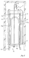
- the car 1 comprises a cab 9 and a car frame 10.
- the cab 9 is made of glass-fibre-reinforced plastic and has a floor 11, side wall panels 12, and a back wall panel 13, among others.
- the side wall panels 12 and back wall panel 13 engage the perimeter of the floor 11.
- the floor 11 and the side wall panels 12 have a sandwich structure of urethane inserted between glass-fibre-reinforced plastic, and thus have a higher rigidity than the other parts.
- roller guides 14 and 15 are provided that engage with the car guide rails 7.
- the cab 9 is thus supported from the car guide rails 7 by means of the car frame 10, through the roller guides 14 and 15.
- the roller guides 14 and 15 are one possible means to engage the guide rails 7.
- Alternative means includes guide shoes.
- the car frame 10, which supports the cab 9, consists of a lower frame 16 and a side frame 17.
- the lower frame 16 is fixed to the floor 11 while the side frame 17 is fixed to the adjacent side wall panel 12 with bolts, etc.
- the side frame 17 consists of a pair of vertical frame members 17a and 17b positioned on the respective left and right sides of the side wall panel 12, and a transverse frame member 17c spanning the upper ends of the frame members 17a and 17b.
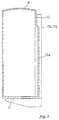
- those parts of the side wall panel 12 of the cab 9 where there are no vertical frame members 17a and 17b or transverse frame member 17c, are formed to bulge outward so that an indentation is formed in the side wall panel 12.
- This bulging part 12a of the side wall panel 12 has an elongate shape which extends from the floor 11 upwards. As shown in Figure 2, the top end of the bulging part 12a is round. The bulging part 12a does not extend outside of the side frame 17.
- the cab 9 has a large capacity with regard to the size of the car 1 as a whole, including the car frame 10. That is, while the cab 9 has a large capacity within the desired design parameters, the car 1 as a whole can still be compact.
- the indentation formed by the bulge 12a in the side wall panel 12 permits the cab to be positioned adjacent the hoist machine 5 and sheave 5a without interference. As a result, the machine 5 and sheave 5a can be disposed in the hoistway without the need to extend the hoistway outward or to reduce the floor area of the cab 9.
- a part of a side wall panel or back wall panel of the cab is made to bulge outward other than where the side frame is located.
- the cab can be made to have a large capacity, while the car as a whole remains compact.
- FIG. 1 to 5 has the lower end of a side wall panel formed as the bulging portion, with the upper end of the panel located inward to form the indentation.
- the indentation may be formed in either end of the side wall panel, or in either one of the side wall panels, or in the back wall panel, in order to accommodate the location of the hoist machine in the hoistway.
Landscapes
- Engineering & Computer Science (AREA)
- Civil Engineering (AREA)
- Mechanical Engineering (AREA)
- Structural Engineering (AREA)
- Cage And Drive Apparatuses For Elevators (AREA)
- Types And Forms Of Lifts (AREA)
- Body Structure For Vehicles (AREA)
Claims (4)
- Système d'ascenseur comprenant une cabine d'ascenseur (9) et une cage (2) définissant un passage pour le mouvement de la cabine d'ascenseur, la cabine comportant un plancher (11) et au moins un panneau de paroi (12), le plancher ayant un périmètre, ledit panneau de paroi comportant une extrémité inférieure et une extrémité supérieure, l'extrémité inférieure du panneau de paroi étant en prise avec le périmètre du plancher, et l'une ou l'autre de l'extrémité supérieure ou de l'extrémité inférieure du panneau de paroi étant décalée vers l'intérieur par rapport à l'autre de ladite extrémité supérieure ou extrémité inférieure, afin de définir une indentation dans la forme de la cabine, caractérisé en ce qu'une machine (5) est disposée dans la cage et ladite indentation est agencée de manière à s'adapter à la présence de la machine lorsque la cabine est adjacente à la machine.
- Système d'ascenseur selon la revendication 1, dans lequel ladite machine (5) est disposée dans la partie supérieure de la cage (2), et ladite indentation est formée dans l'extrémité supérieure dudit panneau de paroi (12).
- Système d'ascenseur selon la revendication 1 ou 2, comprenant, de plus, un étrier de cabine (1) et deux rails de guidage de cabine (7) qui s'étendent à travers la cage, l'étrier de cabine comprenant des moyens pour se mettre en prise avec les rails de guidage, dans lequel ladite machine (5) est montée avec les rails de guidage, et la cabine (9) est disposée dans l'étrier de cabine de façon que ledit panneau de paroi (12) soit face aux rails de guidage.
- Système d'ascenseur selon la revendication 3, dans lequel ledit étrier de cabine (10) est monté en porte-à-faux sur lesdits rails de guidage (7).
Applications Claiming Priority (3)
| Application Number | Priority Date | Filing Date | Title |
|---|---|---|---|
| JP8302620A JPH10139316A (ja) | 1996-11-14 | 1996-11-14 | サイドフォーク型ホームエレベーターのかご構造 |
| JP30262096 | 1996-11-14 | ||
| PCT/US1997/022078 WO1998021139A1 (fr) | 1996-11-14 | 1997-11-14 | Cabine d'ascenseur |
Publications (2)
| Publication Number | Publication Date |
|---|---|
| EP0938445A1 EP0938445A1 (fr) | 1999-09-01 |
| EP0938445B1 true EP0938445B1 (fr) | 2002-04-03 |
Family
ID=17911184
Family Applications (1)
| Application Number | Title | Priority Date | Filing Date |
|---|---|---|---|
| EP97951526A Expired - Lifetime EP0938445B1 (fr) | 1996-11-14 | 1997-11-14 | Cabine d'ascenseur |
Country Status (8)
| Country | Link |
|---|---|
| US (1) | US6026937A (fr) |
| EP (1) | EP0938445B1 (fr) |
| JP (1) | JPH10139316A (fr) |
| CN (1) | CN1081603C (fr) |
| CA (1) | CA2271427A1 (fr) |
| DE (1) | DE69711672T2 (fr) |
| ES (1) | ES2175505T3 (fr) |
| WO (1) | WO1998021139A1 (fr) |
Cited By (1)
| Publication number | Priority date | Publication date | Assignee | Title |
|---|---|---|---|---|
| CN103350940A (zh) * | 2013-07-04 | 2013-10-16 | 大连佳林设备制造有限公司 | 电梯结构垂直输送系统 |
Families Citing this family (11)
| Publication number | Priority date | Publication date | Assignee | Title |
|---|---|---|---|---|
| WO1999065812A1 (fr) * | 1998-06-16 | 1999-12-23 | Mitsubishi Denki Kabushiki Kaisha | Ascenseur |
| FI981887A7 (fi) * | 1998-09-04 | 2000-03-05 | Kone Corp | Hissijärjestely hissikoneiston moottorin lähtömomentin asettamiseksi |
| US6779634B1 (en) * | 1999-12-06 | 2004-08-24 | Wayne M. Slagle | Dumb waiter elevating and lowering platform device |
| AU2003100189C4 (en) * | 2003-03-12 | 2005-01-27 | Eastern Elevators Pty. Limited | Elevator system |
| AU2004220476B2 (en) * | 2003-03-12 | 2007-07-12 | Eastern Elevators Pty. Limited | Elevator system |
| MY141627A (en) * | 2006-06-09 | 2010-05-31 | Inventio Ag | Lift installation and use of such a lift installation for high-speed lifts |
| JP2008087879A (ja) * | 2006-09-29 | 2008-04-17 | Toshiba Elevator Co Ltd | エレベータの乗りかご構造 |
| DE102009005000A1 (de) | 2009-01-09 | 2010-12-02 | Christopher Schiese | Aufzugskabine und Aufzug |
| ES2599259T3 (es) * | 2013-10-10 | 2017-01-31 | Kone Corporation | Un conjunto de terminal de cable y un ascensor |
| JP7341961B2 (ja) * | 2020-08-17 | 2023-09-11 | 東芝エレベータ株式会社 | かご枠 |
| JP7004408B1 (ja) * | 2020-08-17 | 2022-01-21 | 東芝エレベータ株式会社 | レールユニット |
Family Cites Families (6)
| Publication number | Priority date | Publication date | Assignee | Title |
|---|---|---|---|---|
| US1348138A (en) * | 1919-06-12 | 1920-07-27 | Hunt John | Climbing-elevator device |
| DE1077845B (de) * | 1958-04-03 | 1960-03-17 | Kleindienst & Co | Personenfahrstuhl |
| CH555227A (de) * | 1971-08-05 | 1974-10-31 | Modulbau Ag | Vorrichtung zur herstellung von monolithischen, raumgrossen bauwerken aus stahlbeton. |
| GB1540847A (en) * | 1976-09-10 | 1979-02-14 | Hartley Simon Ltd | Lifting beam |
| KR870003910Y1 (ko) * | 1983-04-11 | 1987-12-05 | 미쓰비시전기 주식회사 | 엘리베이터용 카장치(car apparatus) |
| US5207295A (en) * | 1991-10-01 | 1993-05-04 | Otis Elevator Company | Lightweight prefabricated elevator cab |
-
1996
- 1996-11-14 JP JP8302620A patent/JPH10139316A/ja not_active Withdrawn
-
1997
- 1997-11-14 WO PCT/US1997/022078 patent/WO1998021139A1/fr not_active Ceased
- 1997-11-14 US US08/970,225 patent/US6026937A/en not_active Expired - Fee Related
- 1997-11-14 DE DE69711672T patent/DE69711672T2/de not_active Expired - Lifetime
- 1997-11-14 CA CA002271427A patent/CA2271427A1/fr not_active Abandoned
- 1997-11-14 EP EP97951526A patent/EP0938445B1/fr not_active Expired - Lifetime
- 1997-11-14 CN CN97199708A patent/CN1081603C/zh not_active Expired - Fee Related
- 1997-11-14 ES ES97951526T patent/ES2175505T3/es not_active Expired - Lifetime
Cited By (1)
| Publication number | Priority date | Publication date | Assignee | Title |
|---|---|---|---|---|
| CN103350940A (zh) * | 2013-07-04 | 2013-10-16 | 大连佳林设备制造有限公司 | 电梯结构垂直输送系统 |
Also Published As
| Publication number | Publication date |
|---|---|
| US6026937A (en) | 2000-02-22 |
| EP0938445A1 (fr) | 1999-09-01 |
| DE69711672D1 (de) | 2002-05-08 |
| CN1081603C (zh) | 2002-03-27 |
| ES2175505T3 (es) | 2002-11-16 |
| WO1998021139A1 (fr) | 1998-05-22 |
| JPH10139316A (ja) | 1998-05-26 |
| DE69711672T2 (de) | 2002-11-28 |
| CA2271427A1 (fr) | 1998-05-22 |
| CN1237944A (zh) | 1999-12-08 |
Similar Documents
| Publication | Publication Date | Title |
|---|---|---|
| AU762403B2 (en) | Machine-room-less elevator | |
| RU2246440C2 (ru) | Канатный лифт с рабочим шкивом | |
| DE69633347T2 (de) | Antriebsscheibenaufzug | |
| EP0938445B1 (fr) | Cabine d'ascenseur | |
| EP0631968A2 (fr) | Elevateur à poulie de traction avec moteur d'entraînement inférieur | |
| EP1224142B1 (fr) | Monte-charge a cable | |
| US6209686B1 (en) | Car structure | |
| CN1248217A (zh) | 电梯轿厢 | |
| EP0935580B1 (fr) | Rail de guidage de monte-charge | |
| JP4262796B2 (ja) | エレベータのかご吊り構造 | |
| WO2006006228A1 (fr) | Ascenseur | |
| JP4849712B2 (ja) | エレベータ | |
| US6302239B1 (en) | Elevator apparatus with hoisting machine beneath elevator car | |
| JP2001063935A (ja) | エレベータ装置 | |
| US20020139619A1 (en) | Hoistwayless elevator system | |
| JPH1149463A (ja) | 巻き取り式フェッシャープレートおよびその取付方法 | |
| JP2505628B2 (ja) | ダブルデッキエレベ―タ | |
| EP1329411B1 (fr) | Ascenseur | |
| JP2526699B2 (ja) | 主索なしエレベ―タ―の運行路 | |
| EP1328460B1 (fr) | Structure de support pour glissieres d'ascenseurs | |
| JP7558907B2 (ja) | 乗りかご及びエレベーター | |
| WO2003066499A1 (fr) | Cabine d'ascenseur compacte | |
| JP2858518B2 (ja) | エレベーター機械室 | |
| EP1106561A2 (fr) | Forme pour contrepoids d'ascenseur | |
| JP2004123273A (ja) | エレベータの乗りかご |
Legal Events
| Date | Code | Title | Description |
|---|---|---|---|
| PUAI | Public reference made under article 153(3) epc to a published international application that has entered the european phase |
Free format text: ORIGINAL CODE: 0009012 |
|
| 17P | Request for examination filed |
Effective date: 19990531 |
|
| AK | Designated contracting states |
Kind code of ref document: A1 Designated state(s): DE ES FR IT |
|
| GRAG | Despatch of communication of intention to grant |
Free format text: ORIGINAL CODE: EPIDOS AGRA |
|
| 17Q | First examination report despatched |
Effective date: 20010518 |
|
| GRAG | Despatch of communication of intention to grant |
Free format text: ORIGINAL CODE: EPIDOS AGRA |
|
| GRAH | Despatch of communication of intention to grant a patent |
Free format text: ORIGINAL CODE: EPIDOS IGRA |
|
| GRAH | Despatch of communication of intention to grant a patent |
Free format text: ORIGINAL CODE: EPIDOS IGRA |
|
| GRAA | (expected) grant |
Free format text: ORIGINAL CODE: 0009210 |
|
| AK | Designated contracting states |
Kind code of ref document: B1 Designated state(s): DE ES FR IT |
|
| REF | Corresponds to: |
Ref document number: 69711672 Country of ref document: DE Date of ref document: 20020508 |
|
| ET | Fr: translation filed | ||
| REG | Reference to a national code |
Ref country code: ES Ref legal event code: FG2A Ref document number: 2175505 Country of ref document: ES Kind code of ref document: T3 |
|
| PGFP | Annual fee paid to national office [announced via postgrant information from national office to epo] |
Ref country code: FR Payment date: 20021127 Year of fee payment: 6 |
|
| PLBE | No opposition filed within time limit |
Free format text: ORIGINAL CODE: 0009261 |
|
| STAA | Information on the status of an ep patent application or granted ep patent |
Free format text: STATUS: NO OPPOSITION FILED WITHIN TIME LIMIT |
|
| 26N | No opposition filed |
Effective date: 20030106 |
|
| PG25 | Lapsed in a contracting state [announced via postgrant information from national office to epo] |
Ref country code: FR Free format text: LAPSE BECAUSE OF NON-PAYMENT OF DUE FEES Effective date: 20040730 |
|
| REG | Reference to a national code |
Ref country code: FR Ref legal event code: ST |
|
| PGFP | Annual fee paid to national office [announced via postgrant information from national office to epo] |
Ref country code: ES Payment date: 20091117 Year of fee payment: 13 Ref country code: DE Payment date: 20091130 Year of fee payment: 13 |
|
| PGFP | Annual fee paid to national office [announced via postgrant information from national office to epo] |
Ref country code: IT Payment date: 20091123 Year of fee payment: 13 |
|
| REG | Reference to a national code |
Ref country code: DE Ref legal event code: R119 Ref document number: 69711672 Country of ref document: DE Effective date: 20110601 Ref country code: DE Ref legal event code: R119 Ref document number: 69711672 Country of ref document: DE Effective date: 20110531 |
|
| PG25 | Lapsed in a contracting state [announced via postgrant information from national office to epo] |
Ref country code: DE Free format text: LAPSE BECAUSE OF NON-PAYMENT OF DUE FEES Effective date: 20110531 |
|
| PG25 | Lapsed in a contracting state [announced via postgrant information from national office to epo] |
Ref country code: IT Free format text: LAPSE BECAUSE OF NON-PAYMENT OF DUE FEES Effective date: 20101114 |
|
| REG | Reference to a national code |
Ref country code: ES Ref legal event code: FD2A Effective date: 20120110 |
|
| PG25 | Lapsed in a contracting state [announced via postgrant information from national office to epo] |
Ref country code: ES Free format text: LAPSE BECAUSE OF NON-PAYMENT OF DUE FEES Effective date: 20101115 |