EP1106561A2 - Forme pour contrepoids d'ascenseur - Google Patents
Forme pour contrepoids d'ascenseur Download PDFInfo
- Publication number
- EP1106561A2 EP1106561A2 EP00126291A EP00126291A EP1106561A2 EP 1106561 A2 EP1106561 A2 EP 1106561A2 EP 00126291 A EP00126291 A EP 00126291A EP 00126291 A EP00126291 A EP 00126291A EP 1106561 A2 EP1106561 A2 EP 1106561A2
- Authority
- EP
- European Patent Office
- Prior art keywords
- car
- counterweight
- elevator
- motor reducer
- assembly
- Prior art date
- Legal status (The legal status is an assumption and is not a legal conclusion. Google has not performed a legal analysis and makes no representation as to the accuracy of the status listed.)
- Withdrawn
Links
Images
Classifications
-
- B—PERFORMING OPERATIONS; TRANSPORTING
- B66—HOISTING; LIFTING; HAULING
- B66B—ELEVATORS; ESCALATORS OR MOVING WALKWAYS
- B66B17/00—Hoistway equipment
- B66B17/12—Counterpoises
Definitions
- the present invention relates to an elevator car lift assembly.
- the car is normally connected to a vertical rail and is moved along the rail by a lift assembly, which, in most applications, comprises an electric motor reducer housed in a motor compartment of the elevator, and a cable transmission interposed between the reducer and the car and comprising a drive pulley fitted to the motor reducer shaft, and a single counterweight fitted to slide along a rail parallel to the rail of the car.
- the counterweight rail is located on the opposite side of the car to the cable transmission, so that, in use, the counterweight, normally defined by a solid block, slides facing and adjacent to a lateral wall of the elevator shaft.
- known elevators of the above type are far from satisfactory, mainly by failing to enable the motor compartment to be formed at the first-floor or first-stop-floor level of the elevator shaft, i.e. adjacent to a bottom portion of the car rail, as required by current standards governing safe access to the motor reducer and transmission.
- the access opening to the motor compartment must normally be formed through said lateral wall of the elevator shaft, thus preventing uninterrupted access to the motor compartment, as required by current standards, on account of the opening, as the car moves up and down, being closed by the moving counterweight adjacent to the lateral wall of the elevator shaft.
- an elevator car lift assembly comprising a motor reducer; motion transmission means activated by said motor reducer and connected to a car; and a counterweight movable vertically and together with the car between two limit positions and defined at the bottom by a bottom surface; characterized in that said counterweight has a through opening extending from said bottom surface and defined by a top surface raised, in use, with respect to said motor reducer.
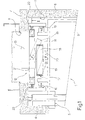
- Number 1 in Figure 1 indicates as a whole a passenger elevator housed inside an elevator shaft indicated by 2 and defined by a front wall 4, in which is formed a door 5 for access to elevator 1, by a back wall 6, and by a lateral wall 7 through which is formed a door 8 for access to elevator shaft 2.
- elevator 1 comprises a car 9, which partly engages elevator shaft 2, is connected to a fixed vertical rail 10, and is moved along rail 10 to and from a bottom limit position by a lift assembly 12 housed in elevator shaft 2.
- Lift assembly 12 comprises a known motor reducer 13 (shown schematically in the accompanying drawings) housed inside a motor compartment 14 of elevator 1 and accessible via door 8.
- motor compartment 14 is formed at a bottom end portion of rail 10, on a level with the first floor 15, and in the space of elevator shaft 2 extending between wall 7 and car 9 when car 9 is in the bottom limit position.
- lift assembly 12 also comprises a cable transmission 17 in turn comprising a number of cables wound about a friction pulley 18 fitted to the output shaft of motor reducer 13, and two idler wheels 19.
- the cables have respective end portions connected to a bracket 20 of car 9, and respective opposite end portions connected to a counterweight 21 connected to a fixed rail 22.
- Rail 22 extends vertically and parallel to rail 10, and is located adjacent to wall 7 and door 8 so that counterweight 21 slides, adjacent to wall 7, between two limit positions.
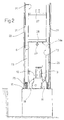
- counterweight 21 is defined by a portal-shaped plate body. More specifically, counterweight 21 comprises two parallel, transversely spaced bottom uprights 23, and a top portion 24 connecting the ends of uprights 23 and defined at the bottom by a surface 24a. Surface 24a extends over motor reducer 13 and defines, together with uprights 23, an opening 25. Opening 25 extends from a surface 26 defining the bottom of counterweight 21, and hence of uprights 23, and is located at door 8 when counterweight 21 is located in a bottom limit position in which counterweight 21 is at least partly housed inside motor compartment 14 and extends astride motor reducer 13. More specifically, opening 25 is the same height as door 8, and is of a width, measured in a direction perpendicular to rail 10, comparable with the width of door 8 and at any rate greater than the transverse dimension of motor reducer 13 measured in the same direction ( Figure 2).
- portion 24 comprises inner bracing in turn comprising an upper cross member 27 for attaching the cables, and a lower cross member 28 fitted integrally with a fastening member 29 projecting inside opening 25 and for fastening hoists or other devices for lifting components, including motor reducer 13, housed inside motor compartment 14.
- counterweight 21 therefore enables access to motor compartment 14 of elevator 1 regardless of the position of car 9 along rail 10 and, hence, regardless of the position of counterweight 21. That is, even when counterweight 21 is located inside motor compartment 14, i.e. at floor 15, opening 25 formed in counterweight 21 permits safe access to motor compartment 14 and the motor reducer, and enables any maintenance to be carried out and even manual operation of car 9.
- cable transmission 17 may be replaced with a different, e.g. hydraulic, transmission; and counterweight 21 may be formed otherwise than as described by way of example, providing access is permitted to motor compartment 14 regardless of the position of counterweight 21 along rail 22.
Landscapes
- Cage And Drive Apparatuses For Elevators (AREA)
- Load-Engaging Elements For Cranes (AREA)
- Lift-Guide Devices, And Elevator Ropes And Cables (AREA)
Applications Claiming Priority (2)
| Application Number | Priority Date | Filing Date | Title |
|---|---|---|---|
| IT1999TO000217 IT248793Y1 (it) | 1999-12-03 | 1999-12-03 | Gruppo di sollevamento cabine per ascensori e ascensore provvisto ditale gruppo |
| ITTO990217U | 1999-12-03 |
Publications (2)
| Publication Number | Publication Date |
|---|---|
| EP1106561A2 true EP1106561A2 (fr) | 2001-06-13 |
| EP1106561A3 EP1106561A3 (fr) | 2002-04-17 |
Family
ID=11417654
Family Applications (1)
| Application Number | Title | Priority Date | Filing Date |
|---|---|---|---|
| EP00126291A Withdrawn EP1106561A3 (fr) | 1999-12-03 | 2000-12-01 | Forme pour contrepoids d'ascenseur |
Country Status (2)
| Country | Link |
|---|---|
| EP (1) | EP1106561A3 (fr) |
| IT (1) | IT248793Y1 (fr) |
Family Cites Families (2)
| Publication number | Priority date | Publication date | Assignee | Title |
|---|---|---|---|---|
| ATE192995T1 (de) * | 1994-06-09 | 2000-06-15 | Aldo Loiodice | Selbsttragendes aufzugsystem und einbaueinrichtung für dessen hauptmotor |
| JPH10250959A (ja) * | 1997-03-07 | 1998-09-22 | Toshiba Elevator Eng Kk | ロープ式エレベータのカウンターウェート |
-
1999
- 1999-12-03 IT IT1999TO000217 patent/IT248793Y1/it active
-
2000
- 2000-12-01 EP EP00126291A patent/EP1106561A3/fr not_active Withdrawn
Also Published As
| Publication number | Publication date |
|---|---|
| IT248793Y1 (it) | 2003-02-20 |
| ITTO990217V0 (it) | 1999-12-03 |
| ITTO990217U1 (it) | 2001-06-03 |
| EP1106561A3 (fr) | 2002-04-17 |
Similar Documents
| Publication | Publication Date | Title |
|---|---|---|
| US6691833B1 (en) | Elevator without a machine room | |
| AU2002339286B2 (en) | Lift system | |
| EP3319896B1 (fr) | Cabine d'ascenseur | |
| US6742628B2 (en) | Rope elevator | |
| CN107522064B (zh) | 电梯 | |
| CN101172557B (zh) | 带有在竖井内两个上下设置的电梯轿厢的电梯 | |
| CN101003343A (zh) | 轿厢自走式电梯 | |
| EP0938445B1 (fr) | Cabine d'ascenseur | |
| CN101128384A (zh) | 具有不对称的导轨的升降机 | |
| EP1377516B1 (fr) | Unite d'entrainement hydraulique montee dans la cage d'ascenseur | |
| EP1106561A2 (fr) | Forme pour contrepoids d'ascenseur | |
| CN212198046U (zh) | 一种顶矮且无圈梁无机房货梯 | |
| MXPA97007934A (en) | Hydraulic elevator that has a contrap | |
| EP1053969B1 (fr) | Ascenseur | |
| FI105123B (fi) | Monitoiminen liitäntä- ja kannatinelementti mekanismissa, joka on tarkoitettu hissien ja nostolaitteiden automaattista oviliikettä varten | |
| KR101998869B1 (ko) | 기계실이 없는 고하중용 엘리베이터 장치 | |
| JP6058710B2 (ja) | エレベータ装置 | |
| EP3274285B1 (fr) | Terminaision d'element de suspension d'un systeme d'ascenseur | |
| JPH04361977A (ja) | 縦横走行エレベータ装置 | |
| EP1760028B1 (fr) | Dispositif de levage sans local de machinerie pour personnes et articles. | |
| JP6692461B2 (ja) | エレベータ装置 | |
| JP2526699B2 (ja) | 主索なしエレベ―タ―の運行路 | |
| KR19990038666A (ko) | 엘리베이터 방식 주차설비의 팰리트 횡행안내장치 | |
| KR20240154856A (ko) | 밀림방지 스토퍼가 구비된 승강기 | |
| JP2015182870A (ja) | エレベータのドア開閉装置 |
Legal Events
| Date | Code | Title | Description |
|---|---|---|---|
| PUAI | Public reference made under article 153(3) epc to a published international application that has entered the european phase |
Free format text: ORIGINAL CODE: 0009012 |
|
| AK | Designated contracting states |
Kind code of ref document: A2 Designated state(s): DE ES FR GB IT PT Kind code of ref document: A2 Designated state(s): AT BE CH CY DE DK ES FI FR GB GR IE IT LI LU MC NL PT SE TR |
|
| AX | Request for extension of the european patent |
Free format text: AL;LT;LV;MK;RO;SI |
|
| PUAL | Search report despatched |
Free format text: ORIGINAL CODE: 0009013 |
|
| AK | Designated contracting states |
Kind code of ref document: A3 Designated state(s): AT BE CH CY DE DK ES FI FR GB GR IE IT LI LU MC NL PT SE TR |
|
| AX | Request for extension of the european patent |
Free format text: AL;LT;LV;MK;RO;SI |
|
| 17P | Request for examination filed |
Effective date: 20021016 |
|
| AKX | Designation fees paid |
Free format text: DE ES FR GB IT PT |
|
| STAA | Information on the status of an ep patent application or granted ep patent |
Free format text: STATUS: THE APPLICATION IS DEEMED TO BE WITHDRAWN |
|
| 18D | Application deemed to be withdrawn |
Effective date: 20070703 |