EP2338738A2 - Moyen de fixation excentrique universel - Google Patents
Moyen de fixation excentrique universel Download PDFInfo
- Publication number
- EP2338738A2 EP2338738A2 EP10466034A EP10466034A EP2338738A2 EP 2338738 A2 EP2338738 A2 EP 2338738A2 EP 10466034 A EP10466034 A EP 10466034A EP 10466034 A EP10466034 A EP 10466034A EP 2338738 A2 EP2338738 A2 EP 2338738A2
- Authority
- EP
- European Patent Office
- Prior art keywords
- eccentric
- universal
- recess
- clamp
- universal eccentric
- Prior art date
- Legal status (The legal status is an assumption and is not a legal conclusion. Google has not performed a legal analysis and makes no representation as to the accuracy of the status listed.)
- Withdrawn
Links
- 238000000034 method Methods 0.000 description 2
- 238000004519 manufacturing process Methods 0.000 description 1
- 239000007787 solid Substances 0.000 description 1
Images


Classifications
-
- B—PERFORMING OPERATIONS; TRANSPORTING
- B60—VEHICLES IN GENERAL
- B60R—VEHICLES, VEHICLE FITTINGS, OR VEHICLE PARTS, NOT OTHERWISE PROVIDED FOR
- B60R7/00—Stowing or holding appliances inside vehicle primarily intended for personal property smaller than suit-cases, e.g. travelling articles, or maps
- B60R7/02—Stowing or holding appliances inside vehicle primarily intended for personal property smaller than suit-cases, e.g. travelling articles, or maps in separate luggage compartment
-
- B—PERFORMING OPERATIONS; TRANSPORTING
- B60—VEHICLES IN GENERAL
- B60P—VEHICLES ADAPTED FOR LOAD TRANSPORTATION OR TO TRANSPORT, TO CARRY, OR TO COMPRISE SPECIAL LOADS OR OBJECTS
- B60P7/00—Securing or covering of load on vehicles
- B60P7/06—Securing of load
- B60P7/08—Securing to the vehicle floor or sides
- B60P7/0807—Attachment points
-
- B—PERFORMING OPERATIONS; TRANSPORTING
- B60—VEHICLES IN GENERAL
- B60R—VEHICLES, VEHICLE FITTINGS, OR VEHICLE PARTS, NOT OTHERWISE PROVIDED FOR
- B60R5/00—Compartments within vehicle body primarily intended or sufficiently spacious for trunks, suit-cases, or the like
- B60R5/04—Compartments within vehicle body primarily intended or sufficiently spacious for trunks, suit-cases, or the like arranged at rear of vehicle
-
- B—PERFORMING OPERATIONS; TRANSPORTING
- B60—VEHICLES IN GENERAL
- B60R—VEHICLES, VEHICLE FITTINGS, OR VEHICLE PARTS, NOT OTHERWISE PROVIDED FOR
- B60R11/00—Arrangements for holding or mounting articles, not otherwise provided for
- B60R2011/0001—Arrangements for holding or mounting articles, not otherwise provided for characterised by position
- B60R2011/0003—Arrangements for holding or mounting articles, not otherwise provided for characterised by position inside the vehicle
- B60R2011/0029—Floor, e.g. side sills, fire wall
-
- B—PERFORMING OPERATIONS; TRANSPORTING
- B60—VEHICLES IN GENERAL
- B60R—VEHICLES, VEHICLE FITTINGS, OR VEHICLE PARTS, NOT OTHERWISE PROVIDED FOR
- B60R11/00—Arrangements for holding or mounting articles, not otherwise provided for
- B60R2011/0001—Arrangements for holding or mounting articles, not otherwise provided for characterised by position
- B60R2011/0003—Arrangements for holding or mounting articles, not otherwise provided for characterised by position inside the vehicle
- B60R2011/0036—Luggage compartment
-
- B—PERFORMING OPERATIONS; TRANSPORTING
- B60—VEHICLES IN GENERAL
- B60R—VEHICLES, VEHICLE FITTINGS, OR VEHICLE PARTS, NOT OTHERWISE PROVIDED FOR
- B60R11/00—Arrangements for holding or mounting articles, not otherwise provided for
- B60R2011/0042—Arrangements for holding or mounting articles, not otherwise provided for characterised by mounting means
- B60R2011/0049—Arrangements for holding or mounting articles, not otherwise provided for characterised by mounting means for non integrated articles
- B60R2011/005—Connection with the vehicle part
- B60R2011/0059—Connection with the vehicle part using clips, clamps, straps or the like
-
- B—PERFORMING OPERATIONS; TRANSPORTING
- B60—VEHICLES IN GENERAL
- B60R—VEHICLES, VEHICLE FITTINGS, OR VEHICLE PARTS, NOT OTHERWISE PROVIDED FOR
- B60R11/00—Arrangements for holding or mounting articles, not otherwise provided for
- B60R2011/0042—Arrangements for holding or mounting articles, not otherwise provided for characterised by mounting means
- B60R2011/0049—Arrangements for holding or mounting articles, not otherwise provided for characterised by mounting means for non integrated articles
- B60R2011/005—Connection with the vehicle part
- B60R2011/0061—Connection with the vehicle part using key-type connections
-
- B—PERFORMING OPERATIONS; TRANSPORTING
- B60—VEHICLES IN GENERAL
- B60R—VEHICLES, VEHICLE FITTINGS, OR VEHICLE PARTS, NOT OTHERWISE PROVIDED FOR
- B60R11/00—Arrangements for holding or mounting articles, not otherwise provided for
- B60R2011/0042—Arrangements for holding or mounting articles, not otherwise provided for characterised by mounting means
- B60R2011/0049—Arrangements for holding or mounting articles, not otherwise provided for characterised by mounting means for non integrated articles
- B60R2011/0064—Connection with the article
- B60R2011/0066—Connection with the article using screws, bolts, rivets or the like
Definitions
- the invention relates to an eccentric tensioning clamp for fastening objects, in particular the objects in the loading space of motor vehicles.
- a universal eccentric clamp which is intended for attachment to the lashing in the recess of the side panel of the cargo space and consists of a body with a fixed lid and a jaw, the body of the two below on the pad and top form side walls interconnected by the upper support member and where the upper recess is formed on the lower surface of the support member and the rotatably mounted jaw has a lower recess on the upper surface, wherein in the secured position the universal eccentric clamp is between the upper recess and the lower recess is the lashing.
- the universal eccentric clamp can be placed on the lashing, the jaw on bolts, where it is pivotally mounted in the openings, which are configured by the recesses in the side walls and the semicircular enclosures on the lid.
- the jaw also has an extension.
- the lid which has a vertical hole with slidably mounted pin, has an upper web with a hole coaxial with the hole in the upper web of the supporting part of the body, wherein in the holes pivotally a lever with eccentric is arranged, which has a surface of the eccentric has.
- the lid has at least one threaded fixing hole.
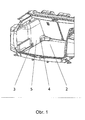
- Fig. 1 an axonometric view of the cargo hold
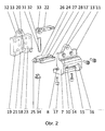
- the Fig. 2 the individual parts of the universal eccentric tension clamp in an axonometric view
- the Fig. 3 the attached to the lashing universal universal eccentric clamp in unlocked position in the cut
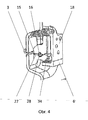
- the Fig. 4 the on the Lashing eye patch universal eccentric tension clamp in locked position in the cut
- the Fig. 5 represents the universal eccentric clamping plate in axonometric view in the attached state.
- the universal eccentric tension clamp 1 is intended for attachment to the lashing eyes 3 , which are fixedly connected to the side part of the vehicle body (not shown) and arranged in depressions 4 of the side panels 5 of the loading space 2 .
- Both the lashing eyes 3 , as well as the depressions 4 have typified dimensions.
- the universal eccentric tension clamp 1 consists of a body 6 to which a lid 18 is fixed, wherein the body 1 consists of a pair of side walls 7 in the form of the letter C with recess 8 , bottom with the pad 9 and top through the upper support member 10 is connected, which merges into the upper web 11 with eyelet 12 , in which an opening 13 is formed. Between the side walls 7 , the pad 9 and the upper support member 10 , a slot 14 is formed. On the lower surface 15 of the upper support member 10 , an upper recess 16 is formed. On the body 6 is fastened with screws 17, a lid 18 having a pair of semicircular enclosures 19 in the lower part.
- the lid 18 further includes a vertical groove 20 and lid recess 21 .
- the holes 12 and 12 'in the assembled state of the body 6 and the lid 18 are coaxial and include a pivotally mounted lever with eccentric 22 .
- the lid 18 has the fixing holes 23 with thread.
- the clamping jaw 24 which has a pair of bolts 25 and an extension 26 .
- a lower recess 28 is formed on the upper surface 27 of the clamping jaw 24 .
- the semicircular enclosures 19 of the cover 18 abut against the recesses 8 in the side walls 7 , whereby a pair of lateral holes 29 is formed.
- the jaw 24 mounted which is partially in the bounded by the slot 14 space in which it is to the bolt 25 is pivotable.
- a pin 30 which rests with the lower end 31 of the spur 26 and at its upper end 32, the surface of the eccentric 33 touches.
- a flat spring 34 is arranged between the pad 9 of the body 6 and the tail 26 of the clamping jaw 24 .
- the universal eccentric tension clamp 1 is attached to the lashing eyes 3 , which are arranged in the depressions 4 of the side panels 5 of the loading space 2 .
- the lever with eccentric 22 is in such a position that the surface of the eccentric 33 does not press on the upper end 32 of the pin 30 .
- the clamping jaw 24 possibly its upper surface 27 , is thus pushed away by the flat spring 34 of the lower surface 15 of the upper support member 10 , whereby a simple placement of the universal eccentric tensioning clamp 1 on the slot 14 on the lashing 3 is made possible.
- the lever After placing the body 6 of the universal eccentric clamp 1 in the recess 4 of the side panel 5 of the loading space 2 , the lever is pivoted with eccentric 22 by approximately 180 °, as a result of which the surface of the eccentric 33 pushes the pin 30 and its pushing movement over the tail 26 is transmitted to the clamping jaw 24 , whereby the lashing 3 , which is fixed in the upper recess 16 through the lower recess 28 , is clamped.
- the position of the so clamped universal eccentric tension clamp 1 is thus clearly delimited against the lashing 3 - they can not move on the lashing 3 both radially, as well as axially and not even pivot about this.
- universal eccentric tension clamp 1 is used as a replaceable component, in which this is fastened by using the fixing holes 23 threaded to the object to be fastened.
- the orientation of the bearing of the eccentric lever 22 can be changed in the composition of the body 6 with the lid 17 , whereby the direction of its tightening can be changed.
Landscapes
- Engineering & Computer Science (AREA)
- Mechanical Engineering (AREA)
- Transportation (AREA)
- Clamps And Clips (AREA)
- Fittings On The Vehicle Exterior For Carrying Loads, And Devices For Holding Or Mounting Articles (AREA)
Applications Claiming Priority (1)
| Application Number | Priority Date | Filing Date | Title |
|---|---|---|---|
| CZ20090856A CZ2009856A3 (cs) | 2009-12-17 | 2009-12-17 | Universální excentrická upínka |
Publications (2)
| Publication Number | Publication Date |
|---|---|
| EP2338738A2 true EP2338738A2 (fr) | 2011-06-29 |
| EP2338738A3 EP2338738A3 (fr) | 2011-12-28 |
Family
ID=43991062
Family Applications (1)
| Application Number | Title | Priority Date | Filing Date |
|---|---|---|---|
| EP10466034A Withdrawn EP2338738A3 (fr) | 2009-12-17 | 2010-12-16 | Moyen de fixation excentrique universel |
Country Status (2)
| Country | Link |
|---|---|
| EP (1) | EP2338738A3 (fr) |
| CZ (1) | CZ2009856A3 (fr) |
Citations (2)
| Publication number | Priority date | Publication date | Assignee | Title |
|---|---|---|---|---|
| EP0939005A1 (fr) | 1998-01-28 | 1999-09-01 | HS Products AG Systemtechnik und Produktmanagement | Dispositif pour fixer des articles dans le compartiment à bagages d'un véhicule |
| CZ293138B6 (cs) | 2000-03-08 | 2004-02-18 | Škoda Auto a. s. | Výklopný hák pro zavěšení zavazadel |
Family Cites Families (4)
| Publication number | Priority date | Publication date | Assignee | Title |
|---|---|---|---|---|
| JP3842530B2 (ja) * | 2000-07-19 | 2006-11-08 | 株式会社ニフコ | 物品保持具 |
| DE202004005126U1 (de) * | 2004-04-01 | 2005-08-18 | Hachenburg, Bruno | Fahrradhalter und Pkw mit Fahrradhalter |
| DE102005000952A1 (de) * | 2005-01-07 | 2006-07-20 | Daimlerchrysler Ag | Haltevorrichtung |
| DE102009033107B4 (de) * | 2009-07-15 | 2020-10-29 | Volkswagen Ag | Vorrichtung zur festen, jedoch lösbaren Befestigung eines Anbauteils an einem tragenden Bauteil eines Fahrzeugs sowie Fahrzeug mit einer derartigen Vorrichtung |
-
2009
- 2009-12-17 CZ CZ20090856A patent/CZ2009856A3/cs unknown
-
2010
- 2010-12-16 EP EP10466034A patent/EP2338738A3/fr not_active Withdrawn
Patent Citations (2)
| Publication number | Priority date | Publication date | Assignee | Title |
|---|---|---|---|---|
| EP0939005A1 (fr) | 1998-01-28 | 1999-09-01 | HS Products AG Systemtechnik und Produktmanagement | Dispositif pour fixer des articles dans le compartiment à bagages d'un véhicule |
| CZ293138B6 (cs) | 2000-03-08 | 2004-02-18 | Škoda Auto a. s. | Výklopný hák pro zavěšení zavazadel |
Also Published As
| Publication number | Publication date |
|---|---|
| EP2338738A3 (fr) | 2011-12-28 |
| CZ2009856A3 (cs) | 2011-06-29 |
Similar Documents
| Publication | Publication Date | Title |
|---|---|---|
| DE3888364T3 (de) | Eine lasttragende vorrichtung. | |
| EP2525998B1 (fr) | Dispositif de support pour accessoire electronique | |
| EP1884410B1 (fr) | Porte-charge | |
| DE10359226B4 (de) | Rollstuhl-Halterungssystem | |
| DE19531018A1 (de) | Gelenkbeschlag für Fahrzeugsitze, insbesondere Kraftfahrzeugsitze | |
| EP2745739A1 (fr) | Dispositif d'accroche pour meuble mural | |
| EP1107878A1 (fr) | Dispositif de fixation pour siege enfant | |
| DE102012110208B4 (de) | Betätigungseinheit für einen Fahrzeugsitz | |
| DE102005056614B4 (de) | Vorrichtung zum Einstellen einer Kippkraft für ein Lkw-Fahrerhaus | |
| DE202016106894U1 (de) | Installationssystem zur Installation von Versorgungsleitungen im Rahmen eines Chassis eines Fahrzeugs | |
| EP3238990B1 (fr) | Pontet d'amarrage et son utilisation | |
| EP2338738A2 (fr) | Moyen de fixation excentrique universel | |
| EP2287045B1 (fr) | Sols de chargement déplaçables | |
| DE2629727C3 (de) | Heb- und absenkbare Auflage | |
| DE102012012489B4 (de) | Sitzunterbau für einen Omnibus | |
| DE3036584A1 (de) | Wagenheber | |
| DE102021209179B4 (de) | Tisch zum Anbringen an einem Sattel eines Fahrrades | |
| DE8801422U1 (de) | Universell verwendbarer Materialträger | |
| DE1655826C3 (de) | Skihaltevorrichtung für Fahrzeuge, insbesondere Kraftfahrzeuge | |
| DE102005019764B4 (de) | Längsverstellbarer Kraftfahrzeugsitz | |
| EP1598489A1 (fr) | Dispositif de fixation pour un élément encastré, encastrable dans une ouverture d'une plaque de support | |
| DE102009013262A1 (de) | Scharniereinrichtung für eine Frontklappe eines Kraftfahrzeugs | |
| DE4039723A1 (de) | Fahrrad- und gepaeckhalter fuer die heckklappe bei fahrzeugen | |
| DE19955964C2 (de) | Anhänger für ein Kraftfahrzeug | |
| DE102018200182B4 (de) | Vorrichtung zur Verbindung eines an einem Kindersitz angebrachten Haltegurts mit einer Karosserie eines Fahrzeugs |
Legal Events
| Date | Code | Title | Description |
|---|---|---|---|
| PUAI | Public reference made under article 153(3) epc to a published international application that has entered the european phase |
Free format text: ORIGINAL CODE: 0009012 |
|
| AK | Designated contracting states |
Kind code of ref document: A2 Designated state(s): AL AT BE BG CH CY CZ DE DK EE ES FI FR GB GR HR HU IE IS IT LI LT LU LV MC MK MT NL NO PL PT RO RS SE SI SK SM TR |
|
| AX | Request for extension of the european patent |
Extension state: BA ME |
|
| PUAL | Search report despatched |
Free format text: ORIGINAL CODE: 0009013 |
|
| AK | Designated contracting states |
Kind code of ref document: A3 Designated state(s): AL AT BE BG CH CY CZ DE DK EE ES FI FR GB GR HR HU IE IS IT LI LT LU LV MC MK MT NL NO PL PT RO RS SE SI SK SM TR |
|
| AX | Request for extension of the european patent |
Extension state: BA ME |
|
| RIC1 | Information provided on ipc code assigned before grant |
Ipc: B60R 7/02 20060101AFI20111122BHEP |
|
| STAA | Information on the status of an ep patent application or granted ep patent |
Free format text: STATUS: THE APPLICATION HAS BEEN WITHDRAWN |
|
| 18W | Application withdrawn |
Effective date: 20120627 |