EP0939156B1 - Method and device for the pneumatic threading of textile machine weft feeders - Google Patents
Method and device for the pneumatic threading of textile machine weft feeders Download PDFInfo
- Publication number
- EP0939156B1 EP0939156B1 EP19990102773 EP99102773A EP0939156B1 EP 0939156 B1 EP0939156 B1 EP 0939156B1 EP 19990102773 EP19990102773 EP 19990102773 EP 99102773 A EP99102773 A EP 99102773A EP 0939156 B1 EP0939156 B1 EP 0939156B1
- Authority
- EP
- European Patent Office
- Prior art keywords
- threading
- pneumatic
- thread
- pneumatic threading
- feeder
- Prior art date
- Legal status (The legal status is an assumption and is not a legal conclusion. Google has not performed a legal analysis and makes no representation as to the accuracy of the status listed.)
- Expired - Lifetime
Links
- 238000000034 method Methods 0.000 title claims description 8
- 239000004753 textile Substances 0.000 title description 3
- 230000003213 activating effect Effects 0.000 claims description 7
- 238000003801 milling Methods 0.000 claims 1
- 238000009826 distribution Methods 0.000 description 3
- 238000003825 pressing Methods 0.000 description 2
- 238000003860 storage Methods 0.000 description 2
- 238000009825 accumulation Methods 0.000 description 1
- 230000004913 activation Effects 0.000 description 1
- 230000000670 limiting effect Effects 0.000 description 1
- 238000004519 manufacturing process Methods 0.000 description 1
- 238000012544 monitoring process Methods 0.000 description 1
- 238000011144 upstream manufacturing Methods 0.000 description 1
- 238000009941 weaving Methods 0.000 description 1
- 238000004804 winding Methods 0.000 description 1
Images

Classifications
-
- D—TEXTILES; PAPER
- D03—WEAVING
- D03D—WOVEN FABRICS; METHODS OF WEAVING; LOOMS
- D03D47/00—Looms in which bulk supply of weft does not pass through shed, e.g. shuttleless looms, gripper shuttle looms, dummy shuttle looms
- D03D47/34—Handling the weft between bulk storage and weft-inserting means
- D03D47/36—Measuring and cutting the weft
- D03D47/361—Drum-type weft feeding devices
-
- B—PERFORMING OPERATIONS; TRANSPORTING
- B65—CONVEYING; PACKING; STORING; HANDLING THIN OR FILAMENTARY MATERIAL
- B65H—HANDLING THIN OR FILAMENTARY MATERIAL, e.g. SHEETS, WEBS, CABLES
- B65H51/00—Forwarding filamentary material
- B65H51/16—Devices for entraining material by flow of liquids or gases, e.g. air-blast devices
-
- B—PERFORMING OPERATIONS; TRANSPORTING
- B65—CONVEYING; PACKING; STORING; HANDLING THIN OR FILAMENTARY MATERIAL
- B65H—HANDLING THIN OR FILAMENTARY MATERIAL, e.g. SHEETS, WEBS, CABLES
- B65H57/00—Guides for filamentary materials; Supports therefor
- B65H57/003—Arrangements for threading or unthreading the guide
-
- B—PERFORMING OPERATIONS; TRANSPORTING
- B65—CONVEYING; PACKING; STORING; HANDLING THIN OR FILAMENTARY MATERIAL
- B65H—HANDLING THIN OR FILAMENTARY MATERIAL, e.g. SHEETS, WEBS, CABLES
- B65H2701/00—Handled material; Storage means
- B65H2701/30—Handled filamentary material
- B65H2701/31—Textiles threads or artificial strands of filaments
Definitions
- the present invention relates to a method and a device for the pneumatic threading of textile machine weft feeders, particularly high-speed weaving looms.
- weft feeders are devices designed to be interposed between the spool and the loom or, more generally, the textile machine in order to allow the correct unwinding of the weft thread from the spool and its correct feeding to the loom, regardless of the stresses to which the thread is subjected by the loom.
- weft feeders typically comprise a fixed drum on which a windmilling arm, located at the base of the drum, winds a reserve of thread.
- a windmilling arm located at the base of the drum, winds a reserve of thread.
- the thread unwinds from the drum of the feeder, and during unwinding its mechanical tension is controlled by a braking means which is arranged at the front end of the drum.
- a monitoring element is provided in order to control the extent of the turn reserve and to activate the windmilling arm in order to restore the reserve, and an advancement means is provided in order to move the turns of the reserve from the base to the front end of the drum.
- the thread that arrives from the spool is guided inside the driving shaft and the windmilling arm of the feeder, both of which are hollow, and after forming the weft reserve on the drum it passes through the braking means and reaches a thread guiding ring, by which it is guided to the loom.
- This path of the thread inside the weft feeder generally makes it troublesome to thread the feeder; the threading is a frequent operation which must be performed at the beginning of each working cycle or if the thread breaks during production.
- Conventional pneumatic threading systems are substantially divided into two categories: partial threading systems, which cause the guided passage of the thread only in the rear side of the feeder, upstream of the reserve accumulation drum; and full threading systems, which provide for the guided automatic passage of the thread from the infeed to the output of the feeder, where the term "output" designates the final thread guiding ring that guides said thread to the loom.
- Systems of the first type have been known and used for many years and substantially employ a controlled pneumatic element which is provided with a thread guiding bush which is arranged at the infeed of the driving shaft of the feeder and has a tapering cross-section which acts like a Venturi tube and into which a stream of pressurized air is injected by means of a suitable duct.
- the air stream by producing a partial vacuum at the infeed of said bush, draws the thread, which is then propelled by the stream into the driving shaft and the windmilling arm.
- the pneumatic element is controlled by an electric valve which is operated by an actuation button and activates or blocks the air stream fed into the bush.
- the system entails the drawback that it only partially facilitates feeder threading, which is in fact completed manually by passing the thread through the braking means and the final thread guiding ring, which are located in front of the drum of the feeder.
- Systems of the second type which are more recent and fully automated, use a first pneumatic element and a second pneumatic element which are respectively associated with the input of the driving shaft and with the final thread guiding ring and are actuated simultaneously by corresponding electric control valves.
- US-A-5 441 087 discloses a feeder, i.e. a yam storage and feed device, with a rear part extending between the point of inlet and the point of outlet of the yam winding element and with a front part extending downstream of said outlet and wherein first pneumatic threading means are provided in said rear part of the said feeder and second pneumatic threading means are provided in said front part of the feeder and disclosing the teaching to activate either simultaneously both of said pneumatic threading means when total failure yarn breakage occurs and the yarn reserve has been totally consumed, or to activate only said first pneumatic threading means when partial failure yarn breakage occurs in said rear part of the feeder and the yarn reserve has not been consumed.
- US-A- 5 487 415 discloses a yam storage and feed device with a first and a second pneumatic threading means, provided in the rear and the front part thereof, respectively and which discloses the teaching to always activate both pneumatic threading mans when yam breakage occurs.
- the aim of the present invention is substantially to eliminate the drawbacks of conventional systems, by combining their respective advantages and therefore by providing a threading method and device which allow the partial threading of the feeder, substantially the threading of the front end part of the feeder, in order to allow, in case of breakage, to tie the thread without having to first remove the residual thread from the drum of the feeder, and likewise allow full threading, which is useful particularly at the beginning of each working cycle or in case of thread replacement and the like.
- the invention is based on the concept of providing the feeder with a first pneumatic threading element and with a second pneumatic threading element which are operatively separate and are located at the infeed and at the output of the feeder, respectively.
- the pneumatic elements are then selectively activated in order to selectively obtain the threading of the front and end feeder parts only, which is achieved by activating the second pneumatic element and by guiding the thread through the braking means and the final output thread guiding ring, or the partial threading of the rear feeder part only, which is achieved by activating the first pneumatic element and by guiding the thread from the infeed of the driving shaft to the base of the drum through the windmilling arm, or the full threading of the feeder, which is obtained by activating the second element after the first one.
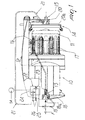
- the reference numeral 10 generally designates a conventional weft feeder which comprises a fixed drum 11 on which a windmilling arm 12, associated with a driving shaft 13 and arranged at the base of the drum 11, winds a plurality of turns of thread F which constitute a thread reserve RF ( Figure 2).
- braking means 14 of a per se known type which are suitable to control the tension of the thread F that unwinds from the drum by passing through a final thread guiding ring 15 which is arranged in front of the drum (relative to the travel of the thread) and is generally designated by the reference numeral 15.
- a feeler 16 which can be mechanical and/or electric, is arranged at the drum 11 in order to monitor the extent of the reserve of turns RS and to activate the windmilling arm 12 in order to replenish the reserve.
- the windmilling arm 12 and the driving shaft 13 are both hollow, in order to receive the thread F that arrives from the spool (not shown) and deposit it on the drum 11 in the form of reserve turns. From the drum, the thread unwinds, when requested by the loom (not shown), by passing through the braking means 14 and the thread guiding ring 15.
- a first pneumatic threading element 18 is arranged at the infeed section of the driving shaft 13 in order to suck up the thread and guide it through the cavities of the driving shaft and of the windmilling arm 12 to the base of the drum 11.
- the pneumatic element 18, which is of a per se known type, is substantially constituted by a bush which has a central channel 18a with a funnel-shaped profile which acts like a Venturi tube into which a duct 19 opens which is inclined in the direction in which the thread travels (shown by the arrow in the figure); the duct 19 feeds a stream of pressurized air into the bush.
- a second pneumatic threading element 20 is associated with the final thread guiding ring 15 and allows to complete the threading of the front part of the feeder 10, sucking up the end of the thread F that is present on the drum 11 and guiding it through the braking means 14, which are released beforehand (i.e., moved away from the drum 11), and through said thread guiding ring 15.
- the pneumatic threading element 20 too is provided with a funnel-shaped cavity 20a into which a respective duct 21 opens which feeds a stream of pressurized air.
- the pressurized air stream which arrives from a source SA, is fed separately to the ducts 19 and 21 by a distribution unit 22 which is provided with electric valves 23 and 24 which control the corresponding ducts and are respectively controlled by a first button 25 and by a second button 26 for selectively activating the duct 19 or the duct 21.
- the button 26 and the respective electric valve 24 can be separate from the distribution unit 22 and can be arranged on the duct 21, for example at the front side of the feeder 10, in order to directly control said duct, which in this case branches off from the pressurized air source SA instead of from the distribution unit 22.
Landscapes
- Engineering & Computer Science (AREA)
- Textile Engineering (AREA)
- Looms (AREA)
Applications Claiming Priority (2)
| Application Number | Priority Date | Filing Date | Title |
|---|---|---|---|
| ITTO980152 IT1302068B1 (it) | 1998-02-26 | 1998-02-26 | Metodo e dispositivo di infilaggio pneumatico di apparecchialimentatori di trama a macchine tessili. |
| ITTO980152 | 1998-02-26 |
Publications (3)
| Publication Number | Publication Date |
|---|---|
| EP0939156A2 EP0939156A2 (en) | 1999-09-01 |
| EP0939156A3 EP0939156A3 (en) | 2001-05-16 |
| EP0939156B1 true EP0939156B1 (en) | 2004-11-03 |
Family
ID=11416482
Family Applications (1)
| Application Number | Title | Priority Date | Filing Date |
|---|---|---|---|
| EP19990102773 Expired - Lifetime EP0939156B1 (en) | 1998-02-26 | 1999-02-23 | Method and device for the pneumatic threading of textile machine weft feeders |
Country Status (3)
| Country | Link |
|---|---|
| EP (1) | EP0939156B1 (it) |
| DE (1) | DE69921524T2 (it) |
| IT (1) | IT1302068B1 (it) |
Cited By (1)
| Publication number | Priority date | Publication date | Assignee | Title |
|---|---|---|---|---|
| US7526776B2 (en) | 2000-12-06 | 2009-04-28 | Microsoft Corporation | Systems and methods for generating and managing filter strings in a filter graph utilizing a matrix switch |
Families Citing this family (1)
| Publication number | Priority date | Publication date | Assignee | Title |
|---|---|---|---|---|
| BE1025268B1 (nl) * | 2017-05-30 | 2019-01-07 | Picanol N.V. Naamloze Vennootschap | Inslagtoevoerinrichting met veerkrachtig gemonteerd drukelement |
Family Cites Families (5)
| Publication number | Priority date | Publication date | Assignee | Title |
|---|---|---|---|---|
| WO1989002944A1 (en) * | 1987-09-25 | 1989-04-06 | Aktiebolaget Iro | Yarn storing and delivering device |
| DE4007131C2 (de) * | 1990-03-07 | 1999-12-30 | Iro Patent Ag Baar | Liefervorrichtung für laufende Fäden |
| DE9117045U1 (de) * | 1991-06-18 | 1995-05-11 | Iro Ab, Ulricehamn | Fadenspeicher- und -liefervorrichtung |
| IT226136Y1 (it) * | 1991-09-19 | 1997-04-18 | Roy Electrotex Spa | Miglioramenti costruttivi per porgitrama per telai di tessitura. |
| IT1259551B (it) * | 1992-04-22 | 1996-03-20 | Lgl Electronics Spa | Dispositivo elettropneumatico per l'infilaggio automatico di apparecchi alimentatori di trama a macchine tessili ed apparecchio alimentatore di trama incorporante detto dispositivo |
-
1998
- 1998-02-26 IT ITTO980152 patent/IT1302068B1/it active IP Right Grant
-
1999
- 1999-02-23 EP EP19990102773 patent/EP0939156B1/en not_active Expired - Lifetime
- 1999-02-23 DE DE1999621524 patent/DE69921524T2/de not_active Expired - Lifetime
Cited By (1)
| Publication number | Priority date | Publication date | Assignee | Title |
|---|---|---|---|---|
| US7526776B2 (en) | 2000-12-06 | 2009-04-28 | Microsoft Corporation | Systems and methods for generating and managing filter strings in a filter graph utilizing a matrix switch |
Also Published As
| Publication number | Publication date |
|---|---|
| DE69921524T2 (de) | 2005-10-27 |
| ITTO980152A1 (it) | 1999-08-26 |
| EP0939156A3 (en) | 2001-05-16 |
| IT1302068B1 (it) | 2000-07-20 |
| DE69921524D1 (de) | 2004-12-09 |
| EP0939156A2 (en) | 1999-09-01 |
Similar Documents
| Publication | Publication Date | Title |
|---|---|---|
| DE60110981T2 (de) | Maschine und Verfahren zur Herstellung eines Kerngarnes | |
| US4893461A (en) | Process and device for piecing with a spinning device operating with a pneumatic twisting unit | |
| US5105614A (en) | Method and apparatus for supplying reserve feed stock to a spinning machine | |
| US4877064A (en) | Device for the automatic control of the weft yarn feed in air looms | |
| US4534387A (en) | Method and apparatus for inserting different weft threads having different properties into the warp shed of a jet weaving machine | |
| CN101868570B (zh) | 用于制造针织品的方法和装置 | |
| US5111852A (en) | Weft inserting nozzle with separate threading duct | |
| JP2863318B2 (ja) | 糸の供給方法 | |
| GB2170828A (en) | Pneumatic thread tensioning device | |
| US4542772A (en) | Apparatus for selectively introducing one or more of a plurality of different weft threads into an air jet weaving machine | |
| KR100636075B1 (ko) | 공압 방적사 인장기 및 방적사 취급 시스템 | |
| US4565225A (en) | Weaving machine | |
| US6039086A (en) | Separating weft thread waste of a single uncontaminated material from untwisted leno binding threads in trimmed catch selvages | |
| JPH101846A (ja) | 織機においてよこ糸の糸通し及び張りを空気式に支援する方法及び装置 | |
| DE102005010534A1 (de) | Schussfadenzuführvorrichtung für Webmaschinen, insbesondere Greiferwebmaschinen | |
| EP0939156A2 (en) | Method and device for the pneumatic threading of textile machine weft feeders | |
| US6009915A (en) | Method and distribution apparatus for pneumatic weft insertion in a series shed loom | |
| DE69014803T2 (de) | Schussfadenliefervorrichtung für Luftwebmaschinen. | |
| CZ240093A3 (en) | Spindleless spinning method and apparatus for making the same | |
| CZ58394A3 (en) | Weft feeder for gripper shuttle and needle looms | |
| US3310933A (en) | Method and apparatus for making a decorative yarn with slubs therein | |
| US4544001A (en) | Weft yarn into the shed of a weaving machine | |
| US20030192614A1 (en) | Method and apparatus for the weft insertion in a jet weaving machine | |
| KR102047283B1 (ko) | 직기용 위사 공급 장치 | |
| EP0999299A2 (en) | Apparatus for the automatically changing of the cones for feeding the yarn to a textile machine and method thereof |
Legal Events
| Date | Code | Title | Description |
|---|---|---|---|
| PUAI | Public reference made under article 153(3) epc to a published international application that has entered the european phase |
Free format text: ORIGINAL CODE: 0009012 |
|
| AK | Designated contracting states |
Kind code of ref document: A2 Designated state(s): BE CH DE IT LI SE |
|
| AX | Request for extension of the european patent |
Free format text: AL;LT;LV;MK;RO;SI |
|
| PUAL | Search report despatched |
Free format text: ORIGINAL CODE: 0009013 |
|
| AK | Designated contracting states |
Kind code of ref document: A3 Designated state(s): AT BE CH CY DE DK ES FI FR GB GR IE IT LI LU MC NL PT SE |
|
| AX | Request for extension of the european patent |
Free format text: AL;LT;LV;MK;RO;SI |
|
| 17P | Request for examination filed |
Effective date: 20011114 |
|
| AKX | Designation fees paid |
Free format text: BE CH DE IT LI SE |
|
| 17Q | First examination report despatched |
Effective date: 20030228 |
|
| GRAP | Despatch of communication of intention to grant a patent |
Free format text: ORIGINAL CODE: EPIDOSNIGR1 |
|
| GRAS | Grant fee paid |
Free format text: ORIGINAL CODE: EPIDOSNIGR3 |
|
| GRAA | (expected) grant |
Free format text: ORIGINAL CODE: 0009210 |
|
| AK | Designated contracting states |
Kind code of ref document: B1 Designated state(s): BE CH DE IT LI SE |
|
| REG | Reference to a national code |
Ref country code: SE Ref legal event code: TRGR |
|
| REG | Reference to a national code |
Ref country code: CH Ref legal event code: EP |
|
| REF | Corresponds to: |
Ref document number: 69921524 Country of ref document: DE Date of ref document: 20041209 Kind code of ref document: P |
|
| REG | Reference to a national code |
Ref country code: CH Ref legal event code: NV Representative=s name: ROTTMANN, ZIMMERMANN + PARTNER AG |
|
| PLBE | No opposition filed within time limit |
Free format text: ORIGINAL CODE: 0009261 |
|
| STAA | Information on the status of an ep patent application or granted ep patent |
Free format text: STATUS: NO OPPOSITION FILED WITHIN TIME LIMIT |
|
| 26N | No opposition filed |
Effective date: 20050804 |
|
| PGFP | Annual fee paid to national office [announced via postgrant information from national office to epo] |
Ref country code: CH Payment date: 20090129 Year of fee payment: 11 |
|
| REG | Reference to a national code |
Ref country code: CH Ref legal event code: PL |
|
| PG25 | Lapsed in a contracting state [announced via postgrant information from national office to epo] |
Ref country code: LI Free format text: LAPSE BECAUSE OF NON-PAYMENT OF DUE FEES Effective date: 20100228 Ref country code: CH Free format text: LAPSE BECAUSE OF NON-PAYMENT OF DUE FEES Effective date: 20100228 |
|
| PGFP | Annual fee paid to national office [announced via postgrant information from national office to epo] |
Ref country code: SE Payment date: 20140226 Year of fee payment: 16 |
|
| REG | Reference to a national code |
Ref country code: SE Ref legal event code: EUG |
|
| PG25 | Lapsed in a contracting state [announced via postgrant information from national office to epo] |
Ref country code: SE Free format text: LAPSE BECAUSE OF NON-PAYMENT OF DUE FEES Effective date: 20150224 |
|
| PGFP | Annual fee paid to national office [announced via postgrant information from national office to epo] |
Ref country code: IT Payment date: 20151125 Year of fee payment: 18 Ref country code: DE Payment date: 20160225 Year of fee payment: 18 |
|
| PGFP | Annual fee paid to national office [announced via postgrant information from national office to epo] |
Ref country code: BE Payment date: 20151228 Year of fee payment: 18 |
|
| PG25 | Lapsed in a contracting state [announced via postgrant information from national office to epo] |
Ref country code: BE Free format text: LAPSE BECAUSE OF NON-PAYMENT OF DUE FEES Effective date: 20170228 |
|
| REG | Reference to a national code |
Ref country code: DE Ref legal event code: R119 Ref document number: 69921524 Country of ref document: DE |
|
| PG25 | Lapsed in a contracting state [announced via postgrant information from national office to epo] |
Ref country code: DE Free format text: LAPSE BECAUSE OF NON-PAYMENT OF DUE FEES Effective date: 20170901 |
|
| REG | Reference to a national code |
Ref country code: BE Ref legal event code: MM Effective date: 20170228 |
|
| PG25 | Lapsed in a contracting state [announced via postgrant information from national office to epo] |
Ref country code: IT Free format text: LAPSE BECAUSE OF NON-PAYMENT OF DUE FEES Effective date: 20170223 |