EP0939204A2 - Kombikraftwerk, Verfahren zu dessen Betrieb, und Dampfkühlungssystem für das Gasturbinenhochtemperaturteil - Google Patents
Kombikraftwerk, Verfahren zu dessen Betrieb, und Dampfkühlungssystem für das Gasturbinenhochtemperaturteil Download PDFInfo
- Publication number
- EP0939204A2 EP0939204A2 EP99102789A EP99102789A EP0939204A2 EP 0939204 A2 EP0939204 A2 EP 0939204A2 EP 99102789 A EP99102789 A EP 99102789A EP 99102789 A EP99102789 A EP 99102789A EP 0939204 A2 EP0939204 A2 EP 0939204A2
- Authority
- EP
- European Patent Office
- Prior art keywords
- steam
- gas turbine
- path
- hot section
- temperature
- Prior art date
- Legal status (The legal status is an assumption and is not a legal conclusion. Google has not performed a legal analysis and makes no representation as to the accuracy of the status listed.)
- Withdrawn
Links
- 238000001816 cooling Methods 0.000 title claims abstract description 54
- 238000000034 method Methods 0.000 title claims abstract description 11
- 238000011084 recovery Methods 0.000 claims abstract description 29
- 230000001105 regulatory effect Effects 0.000 claims abstract description 11
- 238000011144 upstream manufacturing Methods 0.000 claims description 6
- 230000008646 thermal stress Effects 0.000 abstract description 7
- 238000009423 ventilation Methods 0.000 description 3
- 238000001514 detection method Methods 0.000 description 2
- 238000010586 diagram Methods 0.000 description 2
- 238000002485 combustion reaction Methods 0.000 description 1
- 238000012986 modification Methods 0.000 description 1
- 230000004048 modification Effects 0.000 description 1
- 230000000630 rising effect Effects 0.000 description 1
Images
Classifications
-
- F—MECHANICAL ENGINEERING; LIGHTING; HEATING; WEAPONS; BLASTING
- F01—MACHINES OR ENGINES IN GENERAL; ENGINE PLANTS IN GENERAL; STEAM ENGINES
- F01K—STEAM ENGINE PLANTS; STEAM ACCUMULATORS; ENGINE PLANTS NOT OTHERWISE PROVIDED FOR; ENGINES USING SPECIAL WORKING FLUIDS OR CYCLES
- F01K23/00—Plants characterised by more than one engine delivering power external to the plant, the engines being driven by different fluids
- F01K23/02—Plants characterised by more than one engine delivering power external to the plant, the engines being driven by different fluids the engine cycles being thermally coupled
- F01K23/06—Plants characterised by more than one engine delivering power external to the plant, the engines being driven by different fluids the engine cycles being thermally coupled combustion heat from one cycle heating the fluid in another cycle
- F01K23/10—Plants characterised by more than one engine delivering power external to the plant, the engines being driven by different fluids the engine cycles being thermally coupled combustion heat from one cycle heating the fluid in another cycle with exhaust fluid of one cycle heating the fluid in another cycle
- F01K23/106—Plants characterised by more than one engine delivering power external to the plant, the engines being driven by different fluids the engine cycles being thermally coupled combustion heat from one cycle heating the fluid in another cycle with exhaust fluid of one cycle heating the fluid in another cycle with water evaporated or preheated at different pressures in exhaust boiler
- F01K23/108—Regulating means specially adapted therefor
-
- F—MECHANICAL ENGINEERING; LIGHTING; HEATING; WEAPONS; BLASTING
- F01—MACHINES OR ENGINES IN GENERAL; ENGINE PLANTS IN GENERAL; STEAM ENGINES
- F01K—STEAM ENGINE PLANTS; STEAM ACCUMULATORS; ENGINE PLANTS NOT OTHERWISE PROVIDED FOR; ENGINES USING SPECIAL WORKING FLUIDS OR CYCLES
- F01K23/00—Plants characterised by more than one engine delivering power external to the plant, the engines being driven by different fluids
- F01K23/02—Plants characterised by more than one engine delivering power external to the plant, the engines being driven by different fluids the engine cycles being thermally coupled
- F01K23/06—Plants characterised by more than one engine delivering power external to the plant, the engines being driven by different fluids the engine cycles being thermally coupled combustion heat from one cycle heating the fluid in another cycle
- F01K23/10—Plants characterised by more than one engine delivering power external to the plant, the engines being driven by different fluids the engine cycles being thermally coupled combustion heat from one cycle heating the fluid in another cycle with exhaust fluid of one cycle heating the fluid in another cycle
-
- Y—GENERAL TAGGING OF NEW TECHNOLOGICAL DEVELOPMENTS; GENERAL TAGGING OF CROSS-SECTIONAL TECHNOLOGIES SPANNING OVER SEVERAL SECTIONS OF THE IPC; TECHNICAL SUBJECTS COVERED BY FORMER USPC CROSS-REFERENCE ART COLLECTIONS [XRACs] AND DIGESTS
- Y02—TECHNOLOGIES OR APPLICATIONS FOR MITIGATION OR ADAPTATION AGAINST CLIMATE CHANGE
- Y02E—REDUCTION OF GREENHOUSE GAS [GHG] EMISSIONS, RELATED TO ENERGY GENERATION, TRANSMISSION OR DISTRIBUTION
- Y02E20/00—Combustion technologies with mitigation potential
- Y02E20/16—Combined cycle power plant [CCPP], or combined cycle gas turbine [CCGT]
Definitions
- the present invention relates to a so-called gas turbine combined plant or a combined-cycle plant and a method of operating the same.
- the present invention further relates to a steam-cooling system for a hot section in a gas turbine in which the hot section such as a combustor in the gas turbine of the combined-cycle plant may be cooled by steam from an exhaust heat recovery boiler as an example.
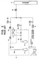
- Fig. 2 is a schematic view showing an example of a gas turbine steam system in conventional combined-cycle plants.
- an exhaust gas from a gas turbine 1 is delivered into an exhaust heat recovery boiler 2.
- the steam from a high-pressure drum 5 in the exhaust heat recovery boiler 2 is delivered into a high-pressure steam turbine 3 through a high-pressure superheater 6 and a high-pressure steam governing valve 13.
- the steam from an intermediate-pressure drum 9 in the exhaust heat recovery boiler 2 is delivered into an intermediate-pressure steam turbine 4 through an intermediate-pressure superheater 10, a reheater 7, and an intermediate-pressure steam governing valve 14 in the order named.
- the steam is then supplied to a hot section 8 from a cooling steam source 12, and is used to cool the hot section 8.
- Auxiliary steam of the power plant or the steam for example, the steam at the outlet of the intermediate-pressure superheater 10) in the exhaust heat recovery boiler 2 may be used as the cooling steam source 12.
- the steam after cooling is then confluent with the steam at the outlet of the reheater 7 to be fed together to the intermediate-pressure steam turbine 4 through the intermediate-pressure steam governing valve 14, as described above.
- Such a combined-cycle plant is provided with a system having the following arrangement.
- the steam temperature detected at a hot section outlet steam temperature detector 15 and the steam temperature detected by a reheater outlet steam temperature detector 16 are both too low to allow the steam to be effectively directed to the intermediate-pressure steam turbine 4.
- an intermediate-pressure steam turbine inlet steam temperature detector 22 is provided to a pipe connected to the intermediate-pressure steam governing valve 14, and detects the steam temperature thereof. While the intermediate-pressure steam governing valve 14 is held closed based upon this detection signal, the steam can by-pass from a turbine by-pass valve 18 to a condenser 11. When the steam temperature rises to reach a tolerance, the intermediate-pressure steam governing valve 14 is then opened based upon the detection signal from the intermediate-pressure steam turbine inlet steam temperature detector 22, resulting in starting up the intermediate-pressure steam turbine 4.
- the temperature detected by the hot section outlet steam temperature detector 15 may be kept considerably higher in rising ratio than the temperature detected by the reheater outlet steam temperature detector 16. This fact indicates that there occurs a large difference between both the outlet steam temperature levels. Accordingly, there is a fear that an undesirable thermal stress be generated at the point, or in the vicinity thereof, where the pipe extending from the reheater 7 and the pipe extending from the hot section 8 are confluent with each other.
- the present invention has been made to overcome the foregoing problem, and an object of the present invention is therefore to provide a gas turbine unit combined plant, a method of operating the same, and a steam-cooling system for a gas turbine hot section, whereby the occurrence of such an undesirable thermal stress can be utmost reduced.
- a gas turbine combined plant in an aspect of the present invention comprises: a first path directing steam from an exhaust heat recovery boiler to a steam turbine unit; a second path branched from the first path, connected to a condenser through a first valve unit; and a third path directing steam after cooling a gas turbine hot section to the first path, wherein a second valve unit is disposed to the third path (assuming that a part of the third path which joins the steam to the first path be provided onto the third path), and the gas turbine combined plant further comprises a fourth path connected to the condenser through a third valve unit from the point located at the upstream side of the second valve unit disposed to the third path.
- a gas turbine combined plant comprises a controller connected to the first valve unit, the second valve unit, and the third valve unit, wherein the first valve unit, the second valve unit, and the third valve unit are opened/closed under the control of the controller.
- a gas turbine combined plant further comprises a first steam temperature detector disposed to the first path for detecting the outlet temperature of the steam of the exhaust heat recovery boiler, and a second steam temperature detector disposed to the third path for detecting the outlet temperature of the steam of the gas turbine hot section, the first steam temperature detector and the second steam temperature detector both being connected to the controller.
- a gas turbine combined plant further comprises a steam turbine inlet steam temperature detector disposed to the first path at the downstream side of the point where the second path is branched from the first path, and a fourth valve unit disposed to the first path at the downstream side of the steam turbine inlet steam temperature detector, the steam turbine inlet steam temperature detector and the fourth valve unit being connected to the controller.
- a gas turbine combined plant further comprises a hot section outlet steam pressure detector for detecting the outlet steam pressure of the gas turbine hot section which occurs at the upstream side of the point where the fourth path is branched from the third path, the hot section outlet steam pressure detector being connected to the controller.
- the present invention provides a method of operating a gas turbine combined plant for introducing the steam after cooling a gas turbine hot section to a path directing steam from an exhaust heat recovery boiler into a steam turbine.
- the method comprises the steps of: detecting the temperature of the steam from the exhaust heat recovery boiler and the temperature of the steam after cooling the gas turbine hot section; and directing a part or the whole steam after cooling the gas turbine hot section to a condenser in the case where the detected temperature has a difference equal to a predetermined value or more.
- a gas turbine hot section steam-cooling system for cooling a hot section of a gas turbine by steam from an exhaust heat recovery boiler and supplying the steam after cooling to a steam turbine.
- the system comprises: a first temperature detector for detecting the outlet temperature of the steam of the hot section of the gas turbine, and a second temperature detector for detecting the outlet temperature of the steam of the exhaust heat recovery boiler at the start-up time of the gas turbine; a shielding valve disposed to a pipe supplying the steam after cooling to the steam turbine from the hot section of the gas turbine for shielding the steam after cooling in the case where there is a substantial difference between the temperature detected by the first temperature detector and the temperature detected by the second temperature detector; and a regulating valve disposed to a pipe connecting the hot section of the gas turbine to a condenser for recovering the steam after cooling to the condenser in the case where there is a substantial difference between the temperature detected by the first temperature detector and the temperature detected by the second temperature detector.
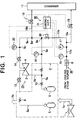
- Fig. 1 illustrates a gas turbine combined plant or a combined-cycle plant incorporating a preferred embodiment of a steam-cooling system for a gas turbine in accordance with the present invention.
- gas turbine unit 1 An exhaust heat recovery boiler 2, a steam turbine unit 23, and the like which all constitute a combined-cycle plant, a steam-cooling system 30, and a control system 40.
- illustration of known elements is omitted and only the elements essential for understanding the present invention is shown. It should be appreciated that these omitted elements also make up this combined-cycle plant.
- an exhaust gas 1a from the gas turbine unit 1 which has driven a generator (not shown) is fed to the exhaust heat recovery boiler 2 to be used for occurrence of steam.
- the gas is thereafter exhausted from the exhaust heat recovery boiler 2, as depicted by an arrow 1b.
- the exhaust heat recovery boiler 2 comprises a high-pressure drum 5, and an intermediate-pressure drum 9.
- a high-pressure superheater 6 and a high-pressure steam governing valve 13 are both connected to a steam pipe 5a that extends beyond the high-pressure drum 5, and the steam pipe 5a is connected to a steam inlet port of a high-pressure steam turbine 3 within the steam turbine unit 23.
- an intermediate-pressure superheater 10, a reheater 7, and an intermediate-pressure steam governing valve (a fourth valve unit) 14 are in turn connected to a steam pipe (a first path) 9a that extends beyond the intermediate-pressure drum 9.
- the steam pipe 9a is connected to a steam inlet port of an intermediate-pressure steam turbine 4 within the steam turbine unit 23.
- a pipe 3a extending beyond an exhaust gas outlet port of the high-pressure steam turbine 3 is connected to the steam pipe 9a at the point located between the intermediate-pressure superheater 10 and the reheater 7, as illustrated in the figure.
- a hot section 8 for example, which may be a combustor of a gas turbine, a hot part, is disposed to a pipe (a third path) 12a in the steam-cooling system 30 which is connected to a cooling steam source 12.
- a shielding valve (a second valve unit) 20 is also connected to the pipe 12a.
- the pipe 12a is further confluent with the pipe 9a at the confluence point 9b located at the downstream side of the shielding valve 20 relative to the direction where the steam flows in the pipe 12a.
- Auxiliary steam of the power plant or steam from the exhaust heat recovery boiler 2 e.g., the steam at the outlet of the intermediate-pressure superheater 10) is suitably used as the cooling steam source 12.
- a pipe (a second path) 18a having a turbine by-pass valve (a first valve unit) 18 is branched from the pipe 9a at the midpoint 9d located between the confluence point 9b and a point 9c to which the intermediate-pressure steam turbine inlet steam temperature detector 22 is attached, and is then connected to a condenser 11.
- a pipe (a fourth path) 19a having a regulating valve (a third valve unit) 19 is connected at one end to the condenser 11.
- the pipe 19a is also connected at the other end to the pipe 12a at the downstream side of a hot section outlet steam temperature detector 15.
- a hot section outlet steam pressure detector 17 is disposed to the pipe 12a. Based upon the signal representing the steam pressure detected by the detector 17, the opening/closing control of the regulating valve 19 can be carried out by an optional controller 21 constituting the control system 40.
- the output signals from the hot section outlet steam temperature detector 15, reheater outlet steam temperature detector 16, hot section outlet steam pressure detector 17, intermediate-pressure steam turbine inlet steam temperature detector 22, and the like are also inputted to the controller 21. Therefore, not only the regulating valve 19 but also the intermediate-pressure steam governing valve 14, the turbine by-pass valve 18, and the shielding valve 20 may be operated in the opening/closing manner under the control of the controller 21.
- the controller 21 is a microcomputer, and can activate a valve driver contained in each valve according to the command from the microcomputer to perform the opening/closing operations for the valves by a known method.
- a known electric sequence circuit may be used in the controller 21.
- a further description will be omitted because persons having ordinary skills in the art can be easy to construct it.
- the hot section outlet steam temperature detector 15 detects a hot section outlet steam temperature which may rise in a relatively short period.
- the reheater outlet steam temperature detector 16 detects a reheater outlet steam temperature which may rise more slowly in a relative manner correspondingly by virtue of the heat capacity of the exhaust heat recovery boiler 2.
- the output signals indicating the above-noted steam temperature are transmitted to the controller 21, where the difference in temperature level between the both output signals is sensed by a comparator (not shown) in the regulating valve 21.
- the reheater outlet steam temperature detected by the reheater outlet steam temperature detector 16 may rise to approach the hot section outlet steam temperature detected by the hot section outlet steam temperature detector 15, and then reach substantially the value equal thereto.
- the reheater outlet steam temperature may reach such a value as to bring the temperature difference to such an extent that no undesirable thermal stress would occur at the pipe portion of the confluence point 9b or in the vicinity thereof, etc. if the both steams are confluent with each other at the confluence point 9b.
- the shielding valve 20 is opened under the control of the controller 21, while the regulating valve 19 is closed stepwise.
- the intermediate-pressure steam governing valve 14 is opened while the turbine by-pass valve 18 is closed, and then the steam is allowed to pass to the intermediate-pressure steam turbine 4.
- a gas turbine combined plant comprises: a first path directing steam from an exhaust heat recovery boiler to a steam turbine unit; a second path branched from the first path, connected to a condenser through a first valve unit; and a third path directing steam after cooling a gas turbine hot section to the first path, wherein a second valve unit is disposed to the third path, and the gas turbine combined plant further comprises a fourth path connected to the condenser through a third valve unit from the point located at the upstream side of the second valve unit disposed to the third path.
- the second valve unit disposed to the third path is closed while the third valve unit disposed to the fourth path is opened.
- a gas turbine combined plant comprises a controller connected to the first valve unit, the second valve unit, and the third valve unit, wherein the first valve unit, the second valve unit, and the third valve unit are opened/closed under the control of the controller.
- a gas turbine combined plant comprises a first steam temperature detector disposed to the first path for detecting the outlet temperature of the steam of the exhaust heat recovery boiler, and a second steam temperature detector disposed to the third path for detecting the outlet temperature of the steam of the gas turbine hot section, the first steam temperature detector and the second steam temperature detector both being connected to the controller.
- a gas turbine combined plant comprises a steam turbine inlet steam temperature detector disposed to the first path at the downstream side of the point where the second path is branched from the first path, and a fourth valve unit disposed to the first path at the downstream side of the steam turbine inlet steam temperature detector, the steam turbine inlet steam temperature detector and the fourth valve unit being connected to the controller.
- a gas turbine combined plant comprises a hot section outlet steam pressure detector for detecting the outlet steam pressure of the gas turbine hot section which occurs at the upstream side of the point where the fourth path is branched from the third path, the hot section outlet steam pressure detector being connected to the controller.
- the opening degree of the third valve unit will be adjustable depending upon the outlet steam pressure of the gas turbine hot section which is detected by the hot section outlet steam pressure detector. This enables the hot section to be effectively cooled.
- a gas turbine combined plant is operated to detect the temperature of the steam from the exhaust heat recovery boiler and the temperature of the steam after cooling the gas turbine hot section and to direct a part or the whole steam after cooling the gas turbine hot section to a condenser in the case where the detected temperature has a difference equal to a predetermined value or more. This will prevent the occurrence of undesirable thermal stress because the steam after cooling does not flow to the steam turbine side and be recovered into the condenser.
- a steam-cooling system for a gas turbine hot section having an arrangement in a gas turbine combined plant incorporates such a steam-cooling system for the gas turbine hot section.
- an undesirable thermal stress may be prevented from occurring at the point where the steam after cooling flowing from the gas turbine hot section steam-cooling system is confluent with the steam flowing to a steam turbine system.
Landscapes
- Engineering & Computer Science (AREA)
- Chemical & Material Sciences (AREA)
- Combustion & Propulsion (AREA)
- Mechanical Engineering (AREA)
- General Engineering & Computer Science (AREA)
- Engine Equipment That Uses Special Cycles (AREA)
Applications Claiming Priority (2)
| Application Number | Priority Date | Filing Date | Title |
|---|---|---|---|
| JP04379098A JP4126108B2 (ja) | 1998-02-25 | 1998-02-25 | ガスタービンコンバインドプラント、その運転方法、及びガスタービン高温部蒸気冷却システム |
| JP4379098 | 1998-02-25 |
Publications (2)
| Publication Number | Publication Date |
|---|---|
| EP0939204A2 true EP0939204A2 (de) | 1999-09-01 |
| EP0939204A3 EP0939204A3 (de) | 2002-01-02 |
Family
ID=12673549
Family Applications (1)
| Application Number | Title | Priority Date | Filing Date |
|---|---|---|---|
| EP99102789A Withdrawn EP0939204A3 (de) | 1998-02-25 | 1999-02-24 | Kombikraftwerk, Verfahren zu dessen Betrieb, und Dampfkühlungssystem für das Gasturbinenhochtemperaturteil |
Country Status (4)
| Country | Link |
|---|---|
| US (1) | US6223520B1 (de) |
| EP (1) | EP0939204A3 (de) |
| JP (1) | JP4126108B2 (de) |
| CA (1) | CA2262722C (de) |
Cited By (1)
| Publication number | Priority date | Publication date | Assignee | Title |
|---|---|---|---|---|
| EP1273768A1 (de) * | 2001-07-05 | 2003-01-08 | Mitsubishi Heavy Industries, Ltd. | Verfahren zum Betrieb eines Kombikraftwerks |
Families Citing this family (14)
| Publication number | Priority date | Publication date | Assignee | Title |
|---|---|---|---|---|
| JP4610722B2 (ja) * | 2000-11-28 | 2011-01-12 | 三菱重工業株式会社 | ガスタービンの蒸気冷却装置 |
| JP4598943B2 (ja) * | 2000-11-28 | 2010-12-15 | 三菱重工業株式会社 | ガスタービンの蒸気冷却装置 |
| US6467273B1 (en) | 2001-03-01 | 2002-10-22 | Henry A. Lott | Method for producing electrical power |
| US6968700B2 (en) | 2001-03-01 | 2005-11-29 | Lott Henry A | Power systems |
| US6841683B2 (en) * | 2001-08-30 | 2005-01-11 | Teva Pharmaceutical Industries Ltd. | Sulfonation method for zonisamide intermediate in zonisamide synthesis and their novel crystal forms |
| EP1293655A1 (de) | 2001-09-13 | 2003-03-19 | Mitsubishi Heavy Industries, Ltd. | Gasturbine, Betriebsmethode derselben und kombiniertes Gasturbinenkraftwerk |
| US8424281B2 (en) * | 2007-08-29 | 2013-04-23 | General Electric Company | Method and apparatus for facilitating cooling of a steam turbine component |
| US20110030335A1 (en) * | 2009-08-06 | 2011-02-10 | General Electric Company | Combined-cycle steam turbine and system having novel cooling flow configuration |
| US9217565B2 (en) * | 2010-08-16 | 2015-12-22 | Emerson Process Management Power & Water Solutions, Inc. | Dynamic matrix control of steam temperature with prevention of saturated steam entry into superheater |
| US9447963B2 (en) | 2010-08-16 | 2016-09-20 | Emerson Process Management Power & Water Solutions, Inc. | Dynamic tuning of dynamic matrix control of steam temperature |
| US9335042B2 (en) | 2010-08-16 | 2016-05-10 | Emerson Process Management Power & Water Solutions, Inc. | Steam temperature control using dynamic matrix control |
| US9163828B2 (en) | 2011-10-31 | 2015-10-20 | Emerson Process Management Power & Water Solutions, Inc. | Model-based load demand control |
| FI127597B (fi) * | 2013-03-05 | 2018-09-28 | Loeytty Ari Veli Olavi | Menetelmä ja laitteisto korkean hyötysuhteen saavuttamiseksi avoimessa kaasuturbiini(kombi)prosessissa |
| CN119879463B (zh) * | 2025-03-28 | 2025-07-22 | 龙南鼎泰电子科技有限公司 | 高效能源站冷却速度控制系统及方法 |
Family Cites Families (21)
| Publication number | Priority date | Publication date | Assignee | Title |
|---|---|---|---|---|
| US3879616A (en) * | 1973-09-17 | 1975-04-22 | Gen Electric | Combined steam turbine and gas turbine power plant control system |
| US3930367A (en) * | 1974-10-23 | 1976-01-06 | General Electric Company | Fluid flow control system |
| DE3261410D1 (en) * | 1981-04-03 | 1985-01-17 | Bbc Brown Boveri & Cie | Combined steam and gas turbine power plant |
| US5170622A (en) * | 1991-04-02 | 1992-12-15 | Cheng Dah Y | Advanced regenerative parallel compound dual fluid heat engine Advanced Cheng Cycle (ACC) |
| JPH06264763A (ja) * | 1993-03-11 | 1994-09-20 | Hitachi Ltd | コンバインドプラントシステム |
| US5412937A (en) * | 1993-11-04 | 1995-05-09 | General Electric Company | Steam cycle for combined cycle with steam cooled gas turbine |
| US5577377A (en) * | 1993-11-04 | 1996-11-26 | General Electric Co. | Combined cycle with steam cooled gas turbine |
| US5428950A (en) * | 1993-11-04 | 1995-07-04 | General Electric Co. | Steam cycle for combined cycle with steam cooled gas turbine |
| DE4409567A1 (de) * | 1994-03-21 | 1995-09-28 | Abb Management Ag | Verfahren zur Kühlung von thermisch belasteten Komponenten einer Gasturbogruppe |
| US5444972A (en) * | 1994-04-12 | 1995-08-29 | Rockwell International Corporation | Solar-gas combined cycle electrical generating system |
| US5579631A (en) * | 1994-04-28 | 1996-12-03 | Westinghouse Electric Corporation | Steam cooling of gas turbine with backup air cooling |
| US5617716A (en) * | 1994-09-16 | 1997-04-08 | Electric Power Research Institute | Method for supplying vaporized fuel oil to a gas turbine combustor and system for same |
| DE19527537C1 (de) * | 1995-07-27 | 1996-09-26 | Siemens Ag | Verfahren zum Betreiben einer Gas- und Dampfturbinenanlage sowie danach arbeitende Anlage |
| EP1184541B1 (de) * | 1995-09-22 | 2004-12-08 | Kabushiki Kaisha Toshiba | Kraftanlage mit kombiniertem Kreislauf |
| JPH09166002A (ja) | 1995-12-14 | 1997-06-24 | Hitachi Ltd | コンバインドサイクル発電プラント |
| JPH09256815A (ja) * | 1996-03-21 | 1997-09-30 | Toshiba Corp | 蒸気冷却ガスタービン,このガスタービンを用いた蒸気冷却コンバインドサイクルプラントおよびその運転方法 |
| US5953900A (en) * | 1996-09-19 | 1999-09-21 | Siemens Westinghouse Power Corporation | Closed loop steam cooled steam turbine |
| US5775091A (en) * | 1996-10-21 | 1998-07-07 | Westinghouse Electric Corporation | Hydrogen fueled power plant |
| JP3564241B2 (ja) * | 1996-10-29 | 2004-09-08 | 三菱重工業株式会社 | コンバインドサイクル発電プラント |
| JP3500020B2 (ja) * | 1996-11-29 | 2004-02-23 | 三菱重工業株式会社 | 蒸気冷却ガスタービンシステム |
| DE69825858T2 (de) * | 1997-06-24 | 2005-09-08 | Mitsubishi Heavy Industries, Ltd. | Dampfkühlungsvorrichtung für gasturbine |
-
1998
- 1998-02-25 JP JP04379098A patent/JP4126108B2/ja not_active Expired - Lifetime
-
1999
- 1999-02-23 CA CA002262722A patent/CA2262722C/en not_active Expired - Fee Related
- 1999-02-23 US US09/255,723 patent/US6223520B1/en not_active Expired - Fee Related
- 1999-02-24 EP EP99102789A patent/EP0939204A3/de not_active Withdrawn
Non-Patent Citations (1)
| Title |
|---|
| None |
Cited By (2)
| Publication number | Priority date | Publication date | Assignee | Title |
|---|---|---|---|---|
| EP1273768A1 (de) * | 2001-07-05 | 2003-01-08 | Mitsubishi Heavy Industries, Ltd. | Verfahren zum Betrieb eines Kombikraftwerks |
| US6666028B2 (en) | 2001-07-05 | 2003-12-23 | Mitsubishi Heavy Industries, Ltd. | Operation method for combined plant |
Also Published As
| Publication number | Publication date |
|---|---|
| JPH11241604A (ja) | 1999-09-07 |
| EP0939204A3 (de) | 2002-01-02 |
| CA2262722C (en) | 2001-10-30 |
| JP4126108B2 (ja) | 2008-07-30 |
| US6223520B1 (en) | 2001-05-01 |
| CA2262722A1 (en) | 1999-08-25 |
Similar Documents
| Publication | Publication Date | Title |
|---|---|---|
| CA2262722C (en) | Gas turbine combined plant, method of operating the same, and steam-cooling system for gas turbine hot section | |
| JP3481983B2 (ja) | 蒸気タービンの始動方法 | |
| US5471832A (en) | Combined cycle power plant | |
| EP0933505B1 (de) | Gekühltes System in einer Kraftanlage mit kombiniertem Kreislauf | |
| EP0928882B1 (de) | Dampfkühlungsvorrichtung für gasturbine | |
| JP3774487B2 (ja) | コンバインドサイクル発電プラント | |
| EP1148210B1 (de) | Dampfkühlung für eine Turbine | |
| JPWO1998059158A1 (ja) | ガスタービン燃焼器蒸気冷却装置 | |
| US6651440B2 (en) | Steam cooling apparatus for gas turbine | |
| US6272841B2 (en) | Combined cycle power plant | |
| JP2000213374A (ja) | ガスタ―ビン燃料加熱システム | |
| JPH09317405A (ja) | 蒸気タービンの高圧初段動翼植込部の冷却装置 | |
| JPH10131716A (ja) | ガスタービン蒸気冷却系統の制御方法及び装置 | |
| EP0978636B1 (de) | Kraftanlage mit kombiniertem kreislauf | |
| JPH1193618A (ja) | ガスタービン蒸気冷却系統の蒸気圧制御方法 | |
| JP3745419B2 (ja) | 排熱回収ボイラ | |
| JP2000345811A (ja) | 排熱回収ボイラプラントとその運転方法 | |
| JPH10131721A (ja) | ガスタービン蒸気系統 | |
| JPH01195903A (ja) | 抽気タービンの抽気制御装置 | |
| JPH06129208A (ja) | 複合サイクルプラント | |
| JPS63117106A (ja) | タ−ビンプラント停止制御方法及び同装置 | |
| JPH06265103A (ja) | 排気再燃型コンバインドサイクル発電プラント | |
| JPH0297801A (ja) | 排熱回収ボイラの補助蒸気抽気方法 | |
| JP2000088209A (ja) | 発電設備 | |
| JPS6038510A (ja) | 再熱器制御装置 |
Legal Events
| Date | Code | Title | Description |
|---|---|---|---|
| PUAI | Public reference made under article 153(3) epc to a published international application that has entered the european phase |
Free format text: ORIGINAL CODE: 0009012 |
|
| AK | Designated contracting states |
Kind code of ref document: A2 Designated state(s): AT BE CH CY DE DK ES FI FR GB GR IE IT LI LU MC NL PT SE Kind code of ref document: A2 Designated state(s): CH DE FR GB IT LI |
|
| AX | Request for extension of the european patent |
Free format text: AL;LT;LV;MK;RO;SI |
|
| PUAL | Search report despatched |
Free format text: ORIGINAL CODE: 0009013 |
|
| AK | Designated contracting states |
Kind code of ref document: A3 Designated state(s): AT BE CH CY DE DK ES FI FR GB GR IE IT LI LU MC NL PT SE |
|
| AX | Request for extension of the european patent |
Free format text: AL;LT;LV;MK;RO;SI |
|
| 17P | Request for examination filed |
Effective date: 20020415 |
|
| AKX | Designation fees paid |
Free format text: CH DE FR GB IT LI |
|
| 17Q | First examination report despatched |
Effective date: 20040429 |
|
| GRAP | Despatch of communication of intention to grant a patent |
Free format text: ORIGINAL CODE: EPIDOSNIGR1 |
|
| STAA | Information on the status of an ep patent application or granted ep patent |
Free format text: STATUS: THE APPLICATION IS DEEMED TO BE WITHDRAWN |
|
| 18D | Application deemed to be withdrawn |
Effective date: 20051228 |