EP1293655A1 - Gasturbine, Betriebsmethode derselben und kombiniertes Gasturbinenkraftwerk - Google Patents
Gasturbine, Betriebsmethode derselben und kombiniertes Gasturbinenkraftwerk Download PDFInfo
- Publication number
- EP1293655A1 EP1293655A1 EP02020245A EP02020245A EP1293655A1 EP 1293655 A1 EP1293655 A1 EP 1293655A1 EP 02020245 A EP02020245 A EP 02020245A EP 02020245 A EP02020245 A EP 02020245A EP 1293655 A1 EP1293655 A1 EP 1293655A1
- Authority
- EP
- European Patent Office
- Prior art keywords
- steam
- temperature
- gas turbine
- casing air
- cooling
- Prior art date
- Legal status (The legal status is an assumption and is not a legal conclusion. Google has not performed a legal analysis and makes no representation as to the accuracy of the status listed.)
- Withdrawn
Links
- 238000000034 method Methods 0.000 title claims description 69
- 238000010248 power generation Methods 0.000 title claims description 26
- 239000002826 coolant Substances 0.000 claims abstract description 173
- 238000005259 measurement Methods 0.000 claims abstract description 4
- 239000007789 gas Substances 0.000 claims description 376
- 238000001816 cooling Methods 0.000 claims description 185
- XLYOFNOQVPJJNP-UHFFFAOYSA-N water Substances O XLYOFNOQVPJJNP-UHFFFAOYSA-N 0.000 claims description 68
- 238000011084 recovery Methods 0.000 claims description 22
- 239000000567 combustion gas Substances 0.000 claims description 14
- 238000002156 mixing Methods 0.000 claims description 10
- 239000000446 fuel Substances 0.000 claims description 9
- 238000002485 combustion reaction Methods 0.000 claims description 7
- 238000004590 computer program Methods 0.000 claims description 7
- 238000010586 diagram Methods 0.000 description 22
- 238000010792 warming Methods 0.000 description 18
- 238000007796 conventional method Methods 0.000 description 16
- 239000002184 metal Substances 0.000 description 13
- 239000007921 spray Substances 0.000 description 12
- 230000004048 modification Effects 0.000 description 10
- 238000012986 modification Methods 0.000 description 10
- 230000000694 effects Effects 0.000 description 7
- 238000011144 upstream manufacturing Methods 0.000 description 7
- 230000008859 change Effects 0.000 description 6
- 229920006395 saturated elastomer Polymers 0.000 description 6
- VNWKTOKETHGBQD-UHFFFAOYSA-N methane Chemical compound C VNWKTOKETHGBQD-UHFFFAOYSA-N 0.000 description 4
- 230000002411 adverse Effects 0.000 description 3
- 238000002347 injection Methods 0.000 description 3
- 239000007924 injection Substances 0.000 description 3
- 238000005070 sampling Methods 0.000 description 3
- 230000035939 shock Effects 0.000 description 3
- 230000001133 acceleration Effects 0.000 description 2
- 238000013459 approach Methods 0.000 description 2
- 238000009833 condensation Methods 0.000 description 2
- 230000005494 condensation Effects 0.000 description 2
- 239000000295 fuel oil Substances 0.000 description 2
- 230000006870 function Effects 0.000 description 2
- 239000007788 liquid Substances 0.000 description 2
- 239000003345 natural gas Substances 0.000 description 2
- 239000003921 oil Substances 0.000 description 2
- 238000010926 purge Methods 0.000 description 2
- 239000005862 Whey Substances 0.000 description 1
- 102000007544 Whey Proteins Human genes 0.000 description 1
- 108010046377 Whey Proteins Proteins 0.000 description 1
- 230000004913 activation Effects 0.000 description 1
- 238000004364 calculation method Methods 0.000 description 1
- 239000000470 constituent Substances 0.000 description 1
- 238000010276 construction Methods 0.000 description 1
- 239000000498 cooling water Substances 0.000 description 1
- 230000003111 delayed effect Effects 0.000 description 1
- 230000005611 electricity Effects 0.000 description 1
- 239000012530 fluid Substances 0.000 description 1
- 230000008569 process Effects 0.000 description 1
- 238000003756 stirring Methods 0.000 description 1
- 230000001629 suppression Effects 0.000 description 1
- 230000008646 thermal stress Effects 0.000 description 1
- 238000009834 vaporization Methods 0.000 description 1
- 230000008016 vaporization Effects 0.000 description 1
- 239000002699 waste material Substances 0.000 description 1
Images




Classifications
-
- F—MECHANICAL ENGINEERING; LIGHTING; HEATING; WEAPONS; BLASTING
- F01—MACHINES OR ENGINES IN GENERAL; ENGINE PLANTS IN GENERAL; STEAM ENGINES
- F01D—NON-POSITIVE DISPLACEMENT MACHINES OR ENGINES, e.g. STEAM TURBINES
- F01D25/00—Component parts, details, or accessories, not provided for in, or of interest apart from, other groups
- F01D25/08—Cooling; Heating; Heat-insulation
- F01D25/12—Cooling
-
- F—MECHANICAL ENGINEERING; LIGHTING; HEATING; WEAPONS; BLASTING
- F01—MACHINES OR ENGINES IN GENERAL; ENGINE PLANTS IN GENERAL; STEAM ENGINES
- F01D—NON-POSITIVE DISPLACEMENT MACHINES OR ENGINES, e.g. STEAM TURBINES
- F01D21/00—Shutting-down of machines or engines, e.g. in emergency; Regulating, controlling, or safety means not otherwise provided for
- F01D21/12—Shutting-down of machines or engines, e.g. in emergency; Regulating, controlling, or safety means not otherwise provided for responsive to temperature
-
- F—MECHANICAL ENGINEERING; LIGHTING; HEATING; WEAPONS; BLASTING
- F01—MACHINES OR ENGINES IN GENERAL; ENGINE PLANTS IN GENERAL; STEAM ENGINES
- F01D—NON-POSITIVE DISPLACEMENT MACHINES OR ENGINES, e.g. STEAM TURBINES
- F01D25/00—Component parts, details, or accessories, not provided for in, or of interest apart from, other groups
- F01D25/08—Cooling; Heating; Heat-insulation
- F01D25/14—Casings modified therefor
-
- F—MECHANICAL ENGINEERING; LIGHTING; HEATING; WEAPONS; BLASTING
- F01—MACHINES OR ENGINES IN GENERAL; ENGINE PLANTS IN GENERAL; STEAM ENGINES
- F01D—NON-POSITIVE DISPLACEMENT MACHINES OR ENGINES, e.g. STEAM TURBINES
- F01D25/00—Component parts, details, or accessories, not provided for in, or of interest apart from, other groups
- F01D25/24—Casings; Casing parts, e.g. diaphragms, casing fastenings
- F01D25/26—Double casings; Measures against temperature strain in casings
-
- F—MECHANICAL ENGINEERING; LIGHTING; HEATING; WEAPONS; BLASTING
- F02—COMBUSTION ENGINES; HOT-GAS OR COMBUSTION-PRODUCT ENGINE PLANTS
- F02C—GAS-TURBINE PLANTS; AIR INTAKES FOR JET-PROPULSION PLANTS; CONTROLLING FUEL SUPPLY IN AIR-BREATHING JET-PROPULSION PLANTS
- F02C7/00—Features, components parts, details or accessories, not provided for in, or of interest apart form groups F02C1/00 - F02C6/00; Air intakes for jet-propulsion plants
- F02C7/12—Cooling of plants
- F02C7/16—Cooling of plants characterised by cooling medium
-
- F—MECHANICAL ENGINEERING; LIGHTING; HEATING; WEAPONS; BLASTING
- F05—INDEXING SCHEMES RELATING TO ENGINES OR PUMPS IN VARIOUS SUBCLASSES OF CLASSES F01-F04
- F05D—INDEXING SCHEME FOR ASPECTS RELATING TO NON-POSITIVE-DISPLACEMENT MACHINES OR ENGINES, GAS-TURBINES OR JET-PROPULSION PLANTS
- F05D2260/00—Function
- F05D2260/20—Heat transfer, e.g. cooling
- F05D2260/232—Heat transfer, e.g. cooling characterized by the cooling medium
- F05D2260/2322—Heat transfer, e.g. cooling characterized by the cooling medium steam
-
- Y—GENERAL TAGGING OF NEW TECHNOLOGICAL DEVELOPMENTS; GENERAL TAGGING OF CROSS-SECTIONAL TECHNOLOGIES SPANNING OVER SEVERAL SECTIONS OF THE IPC; TECHNICAL SUBJECTS COVERED BY FORMER USPC CROSS-REFERENCE ART COLLECTIONS [XRACs] AND DIGESTS
- Y02—TECHNOLOGIES OR APPLICATIONS FOR MITIGATION OR ADAPTATION AGAINST CLIMATE CHANGE
- Y02E—REDUCTION OF GREENHOUSE GAS [GHG] EMISSIONS, RELATED TO ENERGY GENERATION, TRANSMISSION OR DISTRIBUTION
- Y02E20/00—Combustion technologies with mitigation potential
- Y02E20/16—Combined cycle power plant [CCPP], or combined cycle gas turbine [CCGT]
Definitions
- This invention relates to a gas turbine using steam for cooling a high temperature member, a driving method of the gas turbine and a gas turbine combined electric power generation plant.
- Fig. 14 is a partial sectional view of a gas turbine in which steam cooling is applied to the moving blade and the stationary blade.
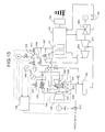
- Fig. 15 is a schematic diagram which shows the gas turbine combined plant in which the steam cooling is employed for a high temperature part.
- thermal energy of exhaust gas of the gas turbine is recovered by an HRSG (Heat Recovery Steam Generator: exhaust heat recovery boiler) 370. Steam is generated by the thermal energy of the exhaust gas of the gas turbine.
- This high temperature and high pressure steam is first supplied to a high pressure steam turbine 350 to drive the same, and electric power is generated by an electric generator 355 connected to the high pressure steam turbine 350.
- Steam which worked in the high pressure steam turbine 350 is introduced into a moving blade 321 through a steam supply pipe 311 provided in the turbine main shaft 310 of the gas turbine. Further, steam is supplied to a stationary blade 325 from a steam supply port 330 provided outside a casing of the gas turbine.
- a cooling flow passages are provided in the moving blade 321 and the stationary blade 325. Steam introduced into the moving blade 321 or the stationary blade 325 observes heat of the combustion gas from an inner wall surface of the flow passage while the steam passes through the cooling flow passage, and the steam is discharged out from the flow passage. Then, steam which has been cooled the moving blade 321 passes through a steam recovery pipe 312 provided in the turbine main shaft 310, and steam which has been cooled the stationary blade 325 is discharged out from the gas turbine through the steam recovery port 331.
- This cooling steam is introduced into a mixer 360 where the steam is mixed with cooling steam which has been cooled a combustor receiver or the like and then, the steam is used as working fluid for driving a intermediate pressure steam turbine 351 or a low pressure steam turbine 352. Steam which has been driven the intermediate pressure steam turbine 351 or the low pressure steam turbine 352 is returned to water and then is supplied to the HRSG 370 by a pump, and the process is repeated again.
- Japanese Patent Application Laid-open No. 10-18809 discloses a technique in which air compressed is bled from an intermediate portion of a compressor, a high temperature portion of a gas turbine is cooled, and when air is switched to steam as the cooling medium, temperatures of the air and steam are controlled to eliminate the temperature difference.
- the cooling air is bled from the intermediate portion of the compressing stage in the compressor, the driving state of the compressor becomes unstable due to stalling of the blade and as a result, cooling state of the high temperature portion also becomes unstable sometimes.
- cooling air supplied to the moving blade becomes unstable and as a result, it becomes difficult to maintain a temperature of the high temperature portion constant, and the driving state of the gas turbine becomes unstable sometimes . It is difficult to maintain a stable driving state in this gas turbine, and a trip of the gas turbine is caused sometimes.
- Each of the movable and stationary blades of a gas turbine is provided therein with a cooling flow passage through which cooling medium flows.
- a temperature of the moving blade and the stationary blade is not sufficiently warmed immediately after the driving of the gas turbine, and when the temperature thereof is lower than a temperature of saturated steam of the cooling steam, the cooling steam is condensed and becomes a drop of water.
- the cooling steam which flowed during the previous driving is condensed and becomes a drop of water and stays in the cooling flow passage sometimes.
- Japanese Patent Application Laid-open No. 11-93693 discloses a driving method of a combined cycle electric power generation plant in which after a high temperature part of a gas turbine is maintained in a vacuum state, a purge operation, a warming operation, a steam cooling operation and a stopping operation are sequentially carried out.
- the moving blade and the stationary blade are independently provided with steam supply systems to cool the moving blade and the stationary blade. Therefore, a great amount of steam is required for cooling the moving blade and the stationary blade.
- the speed of the gas turbine is increased after the start of the turbine and the gas turbine is brought into a constant speed (3000 or 3600 rmp) operating state.
- rotation systems such as the moving blade, a turbine main shaft and the rotor disk are warmed. At that time, casing air supplied from a casing warms these parts and the casing air is about 400°C.
- the cooling medium of the moving blade is switched from the casing air into steam generated in the HRSG. At that time, it is necessary to uniform temperatures of the casing air and the steam so as to prevent the vibration of the shaft.
- a temperature of exhaust gas is about 300°C. Therefore, in the case of the casing air having a temperature of about 400°C, it is necessary to reduce its temperature by about 100°C by means of a cooling unit before it is used for warming the moving blade and the like. Further, energy for cooling the casing air is required, and since the casing air is cooled before it is used, time is required for warming the moving blade and the like, and waste of fuel is generated correspondingly.
- a starting loss i.e., cost capable of obtaining a rating output from the start of the gas turbine is increased.
- a gas turbine comprising: a high temperature member of the gas turbine which uses a gas turbine casing air and steam as cooling medium in a switching manner and which is provided therein with a cooling flow passage; a steam supply unit such as a boiler or the like which supplies cooling steam to the high temperature member; a casing air supplying unit which has an air temperature adjusting unit capable of adjusting air temperature of the gas turbine casing supplied to the high temperature member by controlling at least one of a mixing ratio of air having different temperatures and a cooling amount of air; and a cooling medium switching unit which equalize casing air temperature and steam temperature by the air temperature adjusting unit and then, which switches the cooling medium for the high temperature member from the casing air to the steam.
- the cooling medium which cools the high temperature member of the gas turbine such as the moving blade
- temperatures of the casing air and the steam are equalize and the cooling medium is switched by a switching unit such as a valve.
- a switching unit such as a valve.
- a portion of combustion air formed by a compressor is bled to cool the high temperature member until sufficient cooling steam is generated by exhaust gas of the gas turbine.
- the cooling medium is switched from the casing air to the steam generated by the HRSG.
- the shaft vibration of the entire rotor system including a turbine main shaft, a rotor disk and the like of the gas turbine is increased and it exceeds the permissible value sometimes.
- shaft vibration of the turbine main shaft exceeds the permissible value, since it is danger to further drive the gas turbine, the operation of the gas turbine is stopped (tripped).
- electric power can not be supplied on schedule sometimes, which causes a bottleneck in service.
- the shaft vibration of the entire rotor system including the turbine main shaft is caused when temperature distribution is generated in a circumferential direction of the turbine main shaft or when a temperature distribution is generated in a circumferential direction of a rotor disk connected to the turbine main shaft.
- the temperature distribution is reduced, and it is possible to contain the shaft vibration of the entire rotor system within the permissible value.
- the trip of the gas turbine at the time of switch of the cooling medium can be avoided and thus, the gas turbine can reliably be driven stably. Further, since the generation ratio of the trip in the gas turbine combined electric power generation plant is extremely reduced, electric power can be supplied on schedule.
- gas turbine since the shaft vibration of the entire rotor system when the cooling medium is switched can be suppressed to a degree equal to or lower than the permissible value, it is possible to switch the cooling medium from the casing air to the steam at the parallel-in period of the gas turbine. Thus, it is possible to shorten the time required until the rating load, and the starting loss can be reduced.
- gas turbine is connected to an electric generator
- an electric generator is connected to a gas turbine singularly operated to generate electric power.
- the expression that temperatures of the casing air and the steam are an equalized means that temperatures thereof are ideally equalized, but when the temperature difference therebetween in the actual case is 15°C or less, the shaft vibration of the turbine main shaft and the stationary blade of the entire rotor system can be suppress within the permissible value.
- the condition that the temperature difference is within 15°C is close to a tolerance limit of the shaft vibration. Therefore, in order to more stably switch the cooling medium, the temperature difference is preferably in a range of 12 to 13°C, and more preferably temperature difference is 10°C in view of safety.
- examples of the high temperature members of the gas turbine are the moving blade, the turbine main shaft, the rotor disk, the stationary blade and the like, but in this invention, vibration caused by unbalance of the rotation system due to temperature distribution becomes a problem.
- examples of the high temperature members in this invention are especially the moving blade, the turbine main shaft and the rotor disk (and so forth) .
- a temperature of the casing air and a temperature of steam are equalized by an air temperature adjusting unit.
- a mixing ratio of casing air which passes through a heat exchanger which cools air and casing air which does not passes through the heat exchanger is changed, thereby adjusting a temperature of a casing air after it is mixed.
- a cooling amount of air there are a cooling method for changing the number of fans which cool the heat exchanger through which the casing air flows, and a cooling method for changing the number of fans.
- casing air bled from the casing is used to warm and cool the moving blade, the turbine main shaft or the rotor disk.
- this air is bled from an intermediate portion of the compressor.
- the operating state of the compressor becomes unstable due to lost of speed of the blade and as a result, the moving blade, the turbine main shaft and the like are insufficiently warmed or cooled sometimes. Since the air bled halfway through the compressed operation and thus its pressure is low, and sufficient pressure for flowing through the cooling flow passage provided in the moving blade can not be obtained sometimes. As a result, cooling failure of the moving blade is generated sometimes.
- the casing is a place where completely compressed air is temporarily stored, kinetic energy of air flow is converted into pressure energy. Therefore, a sufficient pressure for allowing the air to flow through the cooling flow passage provided in the moving blade can be obtained. Therefore, when casing air bled from the casing is used, it is possible to stably warm and cool the moving blade and the turbine main shaft and thus, the trip can also be avoided.
- a gas turbine comprising: a high temperature member of the gas turbine which uses a gas turbine casing air and steam as cooling medium in a switching manner and which is provided therein with a cooling flow passage; a steam supply unit such as a boiler or the like which supplies cooling steam to the high temperature member; a water-injecting unit provided between the high temperature member and the steam supply unit and which injects water to the cooling steam and adjusts at least one of the water injecting amount or a water temperature, thereby adjusting a temperature of the steam; an air supply unit which supplies casing air of the gas turbine to the high temperature member; and a cooling medium switching unit which equalizes a casing air temperature and a steam temperature by adjusting the cooling steam temperature by the water-injecting unit and then, which switches the cooling medium for the high temperature member from the casing air to the steam.
- a steam supply unit such as a boiler or the like which supplies cooling steam to the high temperature member
- a water-injecting unit provided between the high temperature member and the steam supply unit and which inject
- the cooling medium when the cooling medium is switched from casing air to steam, water is injected to the steam to adjust a temperature of the steam, and temperatures of the casing air and the steam are equalized.
- a temperature of the steam is abruptly lowered. Therefore, in order to control the temperature swiftly, it is better to adjust a temperature of the steam than adjusting a temperature of the casing air.
- the temperatures of the casing air and the steam can be equalized, it is unnecessary to spend time for adjusting a temperature, and it is possible to equalize the temperatures of the casing air and the steam temperature, it is unnecessary to spend time for adjusting the temperature and therefore, the gas turbine can proceed to the rating operation within a shorter time. Further, it is possible to suppress the starting loss.
- a water-injecting unit is used for adjusting the steam temperature.
- a water spray is provided in an intermediate portion of a pipe of steam, and high pressure water is injected from this water spray. It is possible to adjust a temperature of steam by adjusting at least one of water injecting amount and water temperature. Water having different temperatures may be prepared, and necessary water temperature and injection amount may be calculated from a specific heat of the steam based on deviation between the casing air temperature and steam temperature. This method is preferable because the casing air temperature and steam temperature can be equalized within a shorter time. The adjustment of the steam temperature by water injection only can lower the steam temperature, this adjusting method can be applied to a case such that the steam temperature is higher than the casing air temperature. Therefore, in an actual driving, it is preferable to equalize the casing air temperature and the steam temperature in a state in which the steam temperature is higher than the casing air temperature.
- a gas turbine comprising: a high temperature member of the gas turbine which uses a gas turbine casing air and steam as cooling medium in a switching manner and which is provided therein with a cooling flow passage; a steam supply unit such as a boiler or the like which supplies cooling steam to the high temperature member; a water-injecting unit provided between the high temperature member and the steam supply unit and which injects water to the cooling steam and which adjusts at least one of the water injecting amount or a water temperature, thereby adjusting a temperature of the steam; a casing air supply unit which has at an adjusting unit capable of adjusting an air temperature of the gas turbine casing supplied to the high temperature member by controlling at least one of a mixing ratio of air having different temperatures and an air cooling amount; and a cooling medium switching unit which equalizes a casing air temperature and a steam temperature by controlling at least one of the water-injecting unit and the air temperature adjusting unit and then, switches the cooling medium for the high temperature member from the casing air
- both the temperatures are equalized by at least one of the air temperature adjusting unit and the water-injecting unit which adjust the steam temperature both equalize both the temperatures.
- the casing air temperature and the steam temperature can be equalized using both the air temperature adjusting unit and the water-injecting unit. In this case, it is possible to equalize both the temperatures more swiftly than the gas turbine. Therefore, the turbine can proceed the rating operation within a shorter time, and the starting loss can be reduced.
- the casing air temperature and the steam temperature when the casing air temperature and the steam temperature are equalized, it is preferable that the steam temperature is brought higher than the casing air temperature and then the cooling medium is switched.
- the casing air temperature and the steam temperature can be equalized by selecting or using both the air temperature adjusting unit and the water-injecting unit. In this case, it is possible to equalize both the temperatures without waiting until the steam temperature is brought higher than the casing air temperature and thus, the turbine can proceed the rating operation faster correspondingly, and the starting loss can be reduced.
- a gas turbine comprising: a compressor which compresses air to form combustion air; a combustor which burns fuel and the combustion air generated by the compressor; high temperature members of the gas turbine such as a moving blade, a stationary blade and the like provided therein with a cooling flow passage, in which a temperature of the combustor increased by the combustion gas of the combustor when at least steam is supplied to the cooling flow passage is cooled; and a turbine driven when combustion gas from the combustor is injected to the moving blade, wherein steam which has been cooled at least one of the high temperature members is used as cooling steam for at least one high temperature member other than the at least one high temperature member which has been cooled.
- steam which has been cooled a high temperature member of the gas turbine which requires cooling is used for cooling a moving blade and a combustor which is high temperature members required to be cooled like the stationary blade or combustor receiver. Therefore, since steam which has been cooled a high temperature member can be used for cooling another high temperature member, it is possible to reduce the using amount of steam correspondingly. As a result, it is possible to reduce the starting loss between the start and the rating operation of the gas turbine. Since the steam which corresponds to a temperature level of a high temperature member which is to be cooled can be supplied, labor for adjusting a temperature can be reduced. Further, steam which has been cooled different high temperature members is mixed and it can be used as cooling steam for another high temperature member. Since steam having a temperature suitable for each high temperature member can be formed only by mixing steam after cooling at an appropriate ratio, a temperature can be adjusted easily.
- a control apparatus which switches a cooling medium supplied to a high temperature member of a gas turbine to steam
- the control apparatus comprising: a steam supply unit which supplies steam to a high temperature member of the gas turbine; a water-injecting unit which injects water to steam to adjust a steam temperature; an air temperature adjusting unit which controls at least one of a cooling amount of air and a mixing ratio of air having different temperatures, thereby adjusting a temperature of casing air to be supplied to the high temperature member; and a cooling medium switching unit which switches the cooling medium for the high temperature member from the casing air to the steam
- the gas turbine further comprises a processor which compares the steam temperature and the casing air temperature, and which actuates at least one of the water-injecting unit and the air temperature adjusting unit such that the steam temperature and the casing air temperature are equalized based on the comparison result, and a control section which controls at least one of the water-injecting unit and the air temperature adjusting unit based on
- At least one of the air temperature adjusting unit which adjust a casing air temperature and the water-injecting unit which adjusts a steam temperature thereby equalizing the casing air temperature and the steam temperature.
- the casing air temperature and the steam temperature are used as control parameters, and based on the comparison result, the air adjusting unit and the water-injecting unit are actuated.
- a temperature difference between the casing air temperature and the steam temperature is within 15°C, preferably within a range of 12 to 13°C, and more preferably within 10°C.
- the casing air temperature is reduced by increasing the cooling amount of the air cooling unit, or by increasing a rate of water to be cooled by the air cooling unit.
- the steam temperature is higher, the steam temperature is lowered by increasing the water injection amount in the water-injecting unit or by injecting water of lower temperature.
- the air cooling unit may be controlled to increase a temperature of the casing air. Since a temperature of the casing air when the cooling medium is switched is about 100°C higher than the steam temperature, the casing air is cooled and supplied to the high temperature member. Therefore, when the cooling degree is reduced, it is possible to increase the casing air temperature supplied to the high temperature member. With such control, it is possible to swiftly equalize the casing air temperature and the steam temperature. When both the temperatures are equalized, the cooling medium switching unit is actuated, and the cooling medium of the high temperature member is switched to steam.
- This control apparatus selects the air temperature adjusting unit and the water-injecting unit or uses both the units to control so that the casing air temperature and the steam temperature can be equalized. Therefore, it is possible to equalize both the temperatures without waiting until the steam temperature is brought higher than the casing air temperature and thus, the turbine can proceed the rating operation faster correspondingly, and the starting loss can be reduced.
- a driving method of a gas turbine which switches a cooling medium which cools a high temperature member of the gas turbine from casing air to steam, the method comprising steps of: measuring temperatures of the casing air and the steam, comparing the temperatures of the casing air and the steam, equalizing the casing air temperature and the steam temperature by adjusting the temperature of the casing air based on the comparison result, and equalizing the casing air temperature and the steam temperature and then, switching the cooling medium of the high temperature member from the casing air to the steam.
- both the temperatures are equalized by adjusting the air temperature adjusting unit. Since the casing air temperature when the cooling medium is switched to steam is about 100°C higher than the steam temperature, the casing air temperature is adjusted by the cooling unit and then is supplied to the moving blade. Since the steam temperature when the cooling medium is switched can not be higher than a certain value, when the steamtemperature is lower than the casing air temperature, the casing air temperature and the steam temperature can not be equalized by adjusting the steam temperature. According to this driving method, since the casing air temperature is adjusted, it is possible to equalize the casing air temperature and the steam temperature irrespective of a temperature of steam. Each step in this driving method may be carried out manually.
- the driving method of this gas turbine can be realized using a computer by a program for allowing the computer to execute the driving method of the gas turbine.
- the driving method of the gas turbine of the present invention comprises a step of measuring the casing air temperature and the steam temperature when the cooling medium which cools the high temperature member of the gas turbine is switched from the casing air to steam, a step of comparing the casing air temperature and the steam temperature with each other, a step of equalizing the casing air temperature and the steam temperature by adjusting the steam temperature based on the comparison result, and a step of switching the cooling medium of the high temperature member from the casing air to steam after the casing air temperature and the steam temperature are equalized.
- both the casing air temperature and the steam temperature are equalized by the water-injecting unit which adjusts the steam temperature when the casing air temperature and the steam temperature are equalized.
- the steam temperature can abruptly be lowered and thus, it is possible to control the temperature swiftly.
- it is possible to calculate an mount of water to be injected to lower the steam temperature to a certain value from a specific heat or a temperature of steam of water to be injected it is possible to swiftly control the temperature by injecting water based on this calculation value.
- each step in this driving method may be carried out manually.
- the driving method of this gas turbine can be realized using a computer by a program for allowing the computer to execute the driving method of the gas turbine.
- a driving method of a gas turbine which switches a cooling medium which cools a high temperature member of the gas turbine from casing air to steam, the method comprising steps of: measuring temperatures of the casing air and the steam; comparing the temperatures of the casing air and the steam; equalizing the casing air temperature and the steam temperature by adjusting at least one of the casing air and the steam based on the comparison result; and equalizing the casing air temperature and the steam temperature and then, switching the cooling medium of the high temperature member from the casing air to the steam.
- both the temperatures are equalized by at least one of the air temperature adjusting unit and the water-injecting unit which adjust the steam temperature.
- the air temperature adjusting unit and the water-injecting unit are selected or used to equalize the casing air temperature and the steam temperature. Therefore, even when the steam temperature is lower than the casing air temperature, it is only necessary to adjust the casing air temperature and thus, it is possible to equalize both the temperatures without waiting until the steam temperature becomes higher than the casing air temperature. Therefore, it is possible to shorten a time required to proceed to the rating operation, and the starting loss can be suppressed to a lower value correspondingly.
- the driving method of this gas turbine can be realized using a computer by a program for allowing the computer to execute the driving method of the gas turbine.
- a driving method of a gas turbine which switches a cooling medium of a gas turbine moving blade to steam which has been cooled a high temperature member of the gas turbine such as a stationary blade and the like other than the moving blade, the method comprising steps of: measuring the casing air temperature and the steam temperature, adjusting at least one of the casing air temperature and the steam temperature based on the measurement result, thereby equalizing both the temperatures; and equalizing the casing air temperature and the steam temperature and then, switching the cooling medium of the gas turbine moving blade from casing air to steam.
- steam which has been cooled a stationary blade which is a high temperature member of the gas turbine is used for cooling a moving blade, and when the cooling medium of the moving blade is switched from the casing air to the steam, both the temperatures are equalized and then the cooling medium is switched. Therefore, the shaft vibration of the gas turbine can be suppressed lower than the permissible value and thus, the gas turbine can be operated stably without causing the trip of the gas turbine . Further, since the moving blade is cooled using steam which has been cooled the stationary blade or the like, it is unnecessary to separately supply cooling steam for the moving blade and the stationary blade. Thus, the cooling steam consumption amount can be reduced to half as compared with the conventional gas turbine.
- the warming-up when the warming-up is completed, since a temperature of steam which has been cooled the stationary blade and a temperature of the casing air are substantially equal to each other, when the cooling medium of the moving blade is switched from the casing air to steam which has been cooled the stationary blade, it is unnecessary to adjust both the temperatures almost at all. Therefore, it is unnecessary to cool the casing air and to use the air when the moving blade or the turbine main shaft is warmed, energy required for cooling a part can be saved. Further, since the warming up operation can be carried out at a casing air temperature which is higher than the conventional technique, time required between the start and the rating operation of the gas turbine can be shortened correspondingly. With the effect, it is possible to suppress the starting loss of the gas turbine to a lower value than the conventional technique.
- the casing air temperature and the steam temperature which have been cooled the stationary blade or the like may be adjusted manually.
- the driving method of this gas turbine can be realized using a computer by a program for allowing the computer to execute the driving method of the gas turbine.
- the gas turbine combined electric power generation plant of the present invention comprises the gas turbine, an electric generator connected to the gas turbine, an exhaust heat recovery boiler which generates steam by an exhaust gas of the gas turbine, a pipe which supplies steam generated by the exhaust heat recovery boiler to a high temperature member of the gas turbine and which cools the high temperature member, and a steam turbine to which steam generated by the exhaust heat recovery boiler is supplied and which drives the electric generator to generate electric power.
- this gas turbine combined electric power generation plant include the gas turbine, and when the cooling medium of the high temperature member is to be switched, it is switched after the casing air temperature and the steam temperature are equalized. Therefore, danger of trip of the gas turbine caused by the shaft vibration of the entire rotor system can be minimized. Therefore, the electric power can be supplied on schedule, and the plant can be operated reliably. Further, since the cooling medium can be switched swiftly, the starting loss can also be reduced.
- this gas turbine combined electric power generation plant includes the gas turbine, and steam which has been cooled the stationary blade or the like of the gas turbine is used for cooling the moving blade. Therefore, it is unnecessary to separately supply cooling steam for the moving blade and the stationary blade. Thus, the cooling steam consumption amount can be reduced to half as compared with the conventional gas turbine. Further, the cooling medium of the moving blade is switched from the casing air to the steam which has been cooled the stationary blade without adjusting both the temperatures almost at all. Therefore, when the moving blade or the turbine main shaft is warmed, it is unnecessary to cool the casing air. Thus, energy required for cooling the casing air can be saved.
- the moving blade can be warmed up with a higher temperature, and time required between the start and the rating operation of the plant can be shortened correspondingly. With the effect, it is possible to suppress the starting loss of the electric power generating plant and thus, it is economy.
- Fig. 1 is an explanatory diagram which shows a gas turbine using a steam cooling and a cooling system according to a first embodiment of the present invention.
- This gas turbine warms up a moving blade and the like by means of air supplied from a casing until a warming up operation of the moving blade and the like from activation of the gas turbine is completed. After completion of the warming up operation, a temperature of cooling air supplied from the casing and a temperature of steam supplied from outside of the gas turbine are equalized, and the cooling medium is switched to steam.
- a cooling medium of the moving blade is switched from air to steamwill be explained, but the scope of the present invention is not limited to the moving blade.
- a case such that the cooling medium of a stationary blade is switched from auxiliary steam formed by a boiler in a factory into high pressure steam formed by a high pressure superheater is also included in a scope of the present invention.
- the invention can also be applied to a case such that cooling steam of a combustion receiver is switched to high pressure steam of HRSG from the factory auxiliary steam.
- An electric generator (not shown) connected to a gas turbine 90 is used as a motor, and the gas turbine 90 is actuated.
- the rotation of the gas turbine 90 is increased until a constant rotation number (here, 3600 rpm) is achieved.
- the HRSG (not shown) having great thermal capacity can not sufficiently supply steam yet. Therefore, in order to cool the moving blade 1 of the gas turbine 90, casing air supplied from a casing 3 of the gas turbine 90 is used. This casing air is allowed to flow through a moving blade 1, a turbine main shaft 2 and the like to warm them until metal temperatures thereof become equal to or higher than a saturated temperature of the cooling steam supplied thereafter.
- the steam is condensed after the cooling medium is switched to the cooling steam, which causes inconvenience in a rotation system.
- the saturated temperature of the cooling steam differs depending upon a driving condition and specification of the gas turbine, but the warming up operation is carried out until the metal temperature of the moving blade 1 and the like becomes 250°C or higher.
- a temperature of the casing air supplied from the casing 3 is 400 to 450°C whereas, the metal temperature of the moving blade 1, the turbine main shaft 2 and the like at the time of cold start of the gas turbine 90 is 150 to 250°C. Therefore, when the casing air is supplied to the moving blade 1 as it is, a temperature difference of about 300°C at the maximum is generated between the casing air temperature and the metal temperature of the moving blade 1 and the like. Thus, the moving blade 1 and the turbine main shaft 2 are abruptly expanded by the temperature difference, and excessive thermal stress is abruptly applied to the moving blade 1 and the like, and there is an adverse possibility that deformation and destroy are caused. Further, since the moving blade 1 and the turbine main shaft 2 rotate at high speed, even when there is a slight deformation, the rotation balance largely comes undone and trip (stop of the gas turbine 90 is caused sometimes.
- the metal temperature of the moving blade 1 or the turbine main shaft 2 becomes higher than the casing air temperature at the time of hot start sometimes.
- the moving blade 1 is shrunk, but the casing air does not always uniformly cool the moving blade 1 and the turbine main shaft 2 due to working precision of a cooling flow passage of the moving blade 1 and the turbine main shaft 2 or pressure distribution in the turbine. Therefore, the temperature distribution is generated in the moving blade 1 or the turbine main shaft 2 and as a result, a size is partially deformed, the rotation balance comes undone, and the trip of the gas turbine 90 is caused.
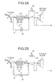
- Fig. 2 is an explanatory diagram which shows the casing air supply system.
- the casing air supply system includes a TCA (Turbine Cooling Air) cooler 20, and a bypass flow passage 21 bypassing the TCA cooler 20.
- the bypass flow passage 21 is provided with a flow-rate adjusting valve 23 which adjust the flow rate of casing air bypassing the TCA cooler 20.
- the flow-rate adjusting valve 23 is closed, all a temperature of the casing air is reduced to about a metal temperature of the moving blade 1 and then is supplied to the moving blade 1 or the like.
- the TCA cooler 20 includes a cooling fan 24.
- the turbine main shaft 2 or the like becomes higher than a saturated temperature of steam supplied after the cooling medium is switched, medium which cools the moving blade 1 or the like is switched to high pressure steam of an HP-SH (High Pressure-Super Heater: high pressure superheater) 80.
- HP-SH High Pressure-Super Heater: high pressure superheater
- a HP-SH pressure adjusting valve 11 is controlled, and a pressure of the high pressure steam supplied from the HP-SH 80 is controlled to about 2 MPa. This is because that the casing air pressure is about 2 MPa, and a pressure difference between the both is reduced, thereby switching the cooling medium as smooth as possible.
- a steam pressure P 1 supplied to the moving blade by a pressure gage 45 is controlled such that a pressure P 2 of the casing air is measured by a pressure gage 46 and a relation P1 > P 2 + ⁇ is always kept.
- the reason why ⁇ is added is that even when the casing air pressure P 2 is abruptly increased by some reason, ⁇ becomes a margin and it is possible to increase the P1 before the P 2 exceeds P1.
- this ⁇ slightly differs depending upon specifications of the gas turbines, when the ⁇ is in a range of 0.15 to 0.20 MPa, even when the casing air pressure P 2 is abruptly increased by some reason, control of pressure can follow the increase.
- Concerning the control of the steam pressure P 1 supplied to the moving blade 1, the P1 can be increased by closing the exhaust valve 13 or opening the HP-SH pressure adjusting valve 11 for example.
- the exhaust valve 13 provided on the cooling flow passage of the moving blade 1 closer to its outlet is closed, and the steam which has been cooled the moving blade 1 is introduced to the mixer 5.
- the steam introduced to the mixer 5 is mixed with steam which has been cooled the cover (not shown) or the stationary blade 4 and drives an intermediate pressure turbine 6.
- the exhaust valve 13 is opened before the cooling medium of the moving blade 1 is switched to steam, and the casing air is discharged outside the. gas turbine from the outlet of the cooling flow passage of the moving blade 1.
- the steam which drove the intermediate pressure turbine 6 is introduced into a steam condenser 7 and returned to water, and is again supplied to the HRSG.
- a steam supply pipe 8 which supplies steam to the moving blade 1 and steam recovery pipes 9 which recover steam after cooling the moving blade 1 are provided in the turbine main shaft 2.
- the steam recovery pipes 9 are annularly provided between the turbine main shaft 2 and the steam supply pipe 8.
- the high pressure steam supplied outside of the gas turbine 90 is introduced into the turbine main shaft 2 from a cooling medium supply port 30.
- steam is supplied in a direction perpendicular to an axial direction of the turbine main shaft 2 and then, the steam turns at a joint portion 35 at an angle of 90° and flows into the steam supply pipe 8 in the turbine main shaft 2.
- the high pressure steam supplied from the HP-SH 80 abruptly changes its flowing direction at the joint portion 35 before being introduced into the steam supply pipe 8 in the turbine main shaft 2. Therefore, the flow of the steam in the steam supply pipe 8 provided in that the turbine main shaft 2 is disordered.
- a plurality of moving blades 1 are mounted around a rotor disk 36 to form one turbine cascade of blades, but cooling flow passages respectively formed in the moving blades 1 are not completely uniformly formed. Because the forming precision of the cooling flow passages provided in the moving blades 1 differs, pressure losses in the cooling flow passages are different. As a result, the amounts of cooling medium flowing in the cooling flow passages are also different. Therefore, steam does not flow uniformly to all of the steam recovery pipes 9 provided in the turbine main shaft 2 and thus, the flow rate of steam differs depending upon pipes.
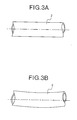
- Fig. 3 is a schematic diagram which shows a case such that a temperature distribution in a circumferential direction is generated in the turbine main shaft 2.
- Fig. 3A shows a case such that the temperature distribution in the circumferential direction is small
- Fig. 3B shows a case such that the temperature distribution in the circumferential direction is great.
- the turbine main shaft 2 is warped as shown in Fig. 3B. Since the turbine main shaft 2 is warped greater as the temperature difference in the circumferential direction becomes greater, the shaft vibration becomes greater and the trip of the gas turbine 90 is finally generated. That is, when a temperature distribution in the circumferential direction is generated in the turbine main shaft 2 and the temperature difference becomes greater, shaft vibration generated in the turbine main shaft 2 is also increased.
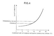
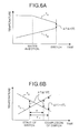
- Fig. 4 is an explanatory diagram which shows a relation between a shaft vibration of the turbine main shaft and a temperature difference between casing air and high pressure steam.
- the shaft vibration is a deflection width from a center axis. It is found as shown in Fig. 4 that when a temperature difference therebetween becomes smaller, a value of the shaft vibration also becomes smaller. The value of the shaft vibration when the temperature difference therebetween exceeds 20°C exceeds a permissible value of operation, and with this value of shaft vibration, a trip of the gas turbine is generated.
- the shaft vibration assumes a value which is permissible for operating the gas turbine, but since this value is close to a tolerance limit, when the gas turbine is operated with this temperature difference, the operation state of the gas turbine becomes slightly unstable.
- a method for equalizing a temperature of casing air and a temperature of high pressure steam will be explained.
- the temperatures of the air and steam can be equalized by adjusting at least one of the temperatures of the casing air and the high pressure steam.
- a water injecting spray 34 is provided between the moving blade 1 and the HP-SH 80 for injecting water to the high pressure steam to lower a temperature of the high pressure steam.
- a high pressure water supply pump 37 is connected to the water injecting spray 34, and water is injected to the high pressure steam supplied from the HP-SH 80.
- the amount of casing air passing through the TCA cooler 20 is increased to warm the pipe of the steam and the temperature of the steam is increased.
- the casing air temperature may be adjusted by reducing the number of fans of the TCA cooler 20 or by reducing the number of rotation of the fan of the TCA cooler 20.
- the cooling medium is switched from the casing air to the high pressure steam.
- the steam temperature is higher the casing air temperature
- cooling water is injected to the high pressure steam by the water injecting spray 34 (see Fig. 1) to lower the steam temperature, and the casing air amount passing through the TCA cooler 20 (see Fig. 2) is reduced to increase the casing air temperature.
- the cooling medium is switched to steam.
- both the temperatures can be equalized within a short time by simultaneously adjusting the casing air temperature and the steam temperature in this manner, a long time is not required for switching the cooling medium, and the starting loss can be reduced.
- Both the temperatures may be equalized by adjusting a temperature of at one of the casing air and the high pressure steam. In this case, although a time for equalizing both the temperatures is increased, both the temperatures abruptly approach each other and as a result, it is possible to suppress a danger that both the temperatures exceed a predetermined range.
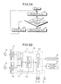
- Figs. 5 are explanatory diagrams which show a control method for equalizing a casing air temperature and a steam temperature.
- Fig. 5A is a flowchart which shows the control method
- Fig. 5B is a block diagram which shows a control apparatus.
- this control method when an absolute value of a difference between a steam temperature and a casing air temperature becomes a value within a predetermined temperature (here, 10°C), the cooling medium is switched to steam.
- a steam temperature Ts is measured by a thermometer 40
- a casing air temperature Ta is measured by a thermometer 41.
- the thermometers 40 and 41 are provided in the vicinity of the cooling medium supply port 30 provided in the gas turbine 90. When the temperatures are measured at these portions, it is sufficient to control the temperature. In order to control more precisely, the temperature may be measured at a position closer to the moving blade 1.
- thermometers 40 and 41 (step S1) measure the steam temperature Ts and the casing air temperature Ta.
- the result of the measurements are respectively sent to measuring devices 131 and 132 and converted into electric signals.
- the electric signals are A/D converted in the measuring devices 131 and 132 and then, are sent to a control apparatus 100.
- a difference therebetween is calculated using a subtracter 111 included in a processor 110 in the control apparatus 100 as a comparing unit.
- a comparator may be used in addition to the subtracter as the comparing unit, and based on the result, a difference between the steam temperature Ts and the casing air temperature Ta may be calculated using an arithmetical unit.
- the A/D converted signal is taken into the subtracter 111 at sampling frequency 500 ms.
- the sampling frequency is a value appropriately set in view of responding speed of control or the like, and it is not limited to 500 ms.
- a control signal is sent to a controller 120 which is a control section from a computing unit 112 (step S2). Then, the moving blade steam control valve 10, the pressure adjusting valve 11 and the exhaust valve 13 are controlled, and the cooling medium is switched to steam (step S4).
- a control signal is sent from the computing unit 112 to the controller 120.
- the TCA cooler 20 or the water injecting apparatus high pressure water supply pump 37 is operated by the controller 120 to control such that the ⁇ t falls within 10°C (step S3).
- the TCA cooler 20 and the water injecting apparatus high pressure water supply pump 37 may be operated at the same time, or only one of them is operated to bring the ⁇ t within 10°C.
- time ⁇ during which both of them are reversed and ⁇ t exceeds 10°C is obtained from the rate of change of the cooling air temperature Ta and the steam temperature Ts, and when ⁇ is shorter than switching time ⁇ c of the cooling medium, the rate of change of the steam temperature Ts or the like is made smooth. More specifically, there is a method in which the water injecting amount is reduced, or a cooling air amount passing through the TCA cooler is increased. With such a method, since ⁇ t does not exceed 10°C from a time point when the switching of the cooling medium is started to a time point when switching of the cooling medium is completed, it is possible to suppress the shaft vibration lower than the permissible value, and to suppress the trip of the gas turbine.
- the processor 110 may be a section realized by a special hardware, or may be a section constituted by a memory and a CPU (Central Arithmetical Unit) and in which a program (not shown) for realizing function of the processor 110 is loaded in the memory to execute the same.
- the control apparatus 100 may be an apparatus in which an input device, a display device and the like (not shown) are loaded to a memory to execute the same, thereby realizing the function.
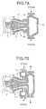
- Fig. 7 is a partial sectional view which shows a gas turbine according to a second embodiment of the invention.
- the second embodiment is such that this gas turbine includes a manifold for stagnating the cooling medium immediately upstream of a pipe entering the turbine main shaft 2 which supplies the cooling medium to the moving blade, this manifold stagnates the cooling medium and then, the cooling medium is supplied to a cooling medium supplying pipe provided in the turbine main shaft 2.
- the reason whey the trip of the gas turbine is generated when the cooling medium of the moving blade is switched from the casing air to the high pressure steam is that thermal expansion is generated by a temperature difference generated in a rotation system of the gas turbine such as the moving blade, the turbine main shaft and the rotor disk.
- a temperature distribution in the circumferential direction is generated in the turbine main shaft 2
- the turbine main shaft 2 is warped (see Fig. 3), this causes the shaft vibration and the trip of the gas turbine.
- One of factor causing the temperature distribution in the turbine main shaft 2 is that steam which is the cooling medium unevenly flows into the steam supply pipe 8 or the steam recovery pipe 9 (see Fig. 1) provided in the turbine main shaft 2.
- the steam which is the cooling medium is stagnated by a manifold 70 provided at upstream of the steam supply pipe 8.
- the steam flows into the steam supply pipe 8 such that substantially uniform speed distribution can be obtained in a cross section perpendicular to the axial direction. Therefore, temperature distribution in the circumferential direction is not generated almost at all in the turbine main shaft 2 and thus, warp of the turbine main shaft 2 due to a great temperature distribution is not generated almost at all.
- the trip of gas turbine is not generated almost at all.
- the steam supply pipe 8 maybe provided outside the steam recovery pipe 9.
- a manifold 71 is provided around the steam supply pipe 8 to supply steam.
- steam is supplied to steam supply pipes 8.
- steam flows substantially uniformly into all the steam supply pipes 8 and thus, substantially uniform temperature distribution in the circumferential direction can be obtained in the turbine main shaft 2. Therefore, warp of the turbine main shaft 2 due to the temperature distribution generated in the turbine main shaft 2 is not generated almost at all.
- the shaft vibration of the turbine main shaft 2 is suppressed lower than the permissible value, and the trip of the gas turbine is not generated almost at all.
- Fig. 8 is a partial sectional view which shows a first modification of the gas turbine of the second embodiment of the invention.
- This gas turbine is such that a swirler 72 which stirs the cooling medium is provided at upstream of the cooling medium supply pipe which supplies the cooling medium to the moving blade, therebymaking a temperature of the cooling medium uniform.
- Another reason why the temperature distribution is generated in the turbine main shaft 2 is that a temperature of the steam which is the cooling medium differs depending upon a position.
- the steam is sufficiently stirred by the swirler 72 to make the temperature distribution uniform as complete as possible.
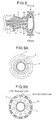
- Fig. 9 is a sectional view which shows a second modification of the gas turbine of the second embodiment of the invention which is perpendicular to an axial direction thereof.
- This gas turbine is such that the number of steam recovery pipes 9 which recovers steam which has been cooled the moving blade is increased, and the temperature distribution in the circumferential direction of the turbine main shaft is made more uniform.
- the number of steam recovery pipes 9 provided in the turbine main shaft 2 is 8 to 12. Therefore, as shown in Fig. 9B, 8 to 12 high temperature portions and 8 to 12 low temperature portions are generated in the turbine main shaft 2. Therefore, when the flow rate of steam flowing through the respective steam recovery pipes 9 is different, the temperature distribution is relatively prone to be generated in an axial direction of the turbine main shaft 2. Thereupon, as shown in Fig.
- the number of steam recovery pipes 9 of the gas turbine of this modification is increased.
- the temperature distribution in the circumferential direction of the turbine main shaft 2 is prone to be uniform.
- shaft vibration of the entire rotor system including the turbine main shaft 2 and the rotor disk can be suppressed lower than the permissible value, and the gas turbine can be operated.
- any of the three kinds of units i.e., increase in the number of manifolds, the swirlers and cooling medium supply pipes, in accordance with specification of the gas turbine, or the units can be combined.
- the two or more of the three units are combined and used, it is effective because the temperature distribution in the circumferential direction of the turbine main shaft can be made uniform.
- a method for equalizing temperatures of the casing air and steam may also be used. When this method is used, since the temperature distribution in the circumferential direction of the turbine main shaft can be made uniform, the tip of the gas turbine can further be suppressed, and the gas turbine can be operated stably.
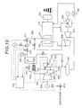
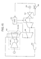
- Fig. 10 is an explanatory diagram which shows a case such that the gas turbine of the invention is applied to a gas turbine combined electric power generation plant.
- This gas turbine combined electric power generation plant is such that it includes a gas turbine using a steam cooling system for a high temperature member such as a moving blade and a stationary blade, and when the cooling medium of the moving blade is switched from casing air to steam, temperatures of both are equalized.
- a gas turbine 500 includes a compressor 505, a combustor 546 and a turbine 530.
- High temperature and high pressure air compressed by the compressor 505 is introduced into the combustor 546.
- gas fuel such as natural gas or liquid fuel such as light oil and light heavy oil is injected to this high temperature and high pressure air to burn them, and high temperature combustion gas is generated.
- the combustion gas passes through a combustor receiver 545 and is injected to the turbine 530, and the thermal energy of the high temperature and high pressure combustion gas is converted into rotation energy in the turbine 530.
- the compressor 505 is driven by the rotation energy
- the electric generator 600 is driven by remaining rotation energy driven the compressor 505 to generate electric power.
- the gas turbine 500 is actuated by an electric generator 600 and then is accelerated, the gas turbine is brought into a constant speed operation at constant rotation number (3000 or 3600 rpm), and warms a moving blade 531, a turbine main shaft 532 and the like by casing air bled from the casing 503.
- the moving blade 531 and the HP-SH 721 are connected to each other through a pipe 550 which supplies steam to a moving blade 531 as a high temperature member, and after the warming up operation, cooling medium of the moving blade 531 is switched from casing air to high pressure steam of the HP-SH 721. At that time, temperatures of the casing air and the high pressure steam are equalized, more specifically, a temperature difference therebetween is set within 10°C and then, the cooling medium is switched.
- Amanner to set the temperature difference therebetween within 10°C is as described above, i.e., a TCA cooler 520 or a water injecting spray 534 is actuated by a control apparatus 100, thereby setting the temperature difference therebetween within 10°C.
- pressure adjusting valves 511, 510, 513 and the like are opened and closed to switch the cooling medium to high pressure steam.
- Fig. 11 is an explanatory diagram which shows a cooling system of a gas turbine of a fourth embodiment of the invention.
- This gas turbine is such that steam which has been cooled a stationary blade 4 as a high temperature member of the gas turbine is used for cooling a moving blade 1.
- independent steam supply systems are provided for the moving blade and the stationary blade to cool them. Further, for a while after the gas turbine is started, it is necessary to warm up the rotation system such as the moving blade, the turbine main shaft and the rotor disk by air supplied from the casing 3 of the gas turbine.
- a temperature of the casing air supplied from the casing 3 is about 400°C.
- a temperature the exhaust gas is as low as 300°C as compared with a case such that a rating load is applied to the gas turbine.
- a temperature of steam of the HP-SH 80 is about 300°C.
- the cooling medium when the cooling medium is switched from the casing air to the steam, it is necessary to equalize the temperatures of the casing air and the steam.
- the casing air is cooled to about 10°C by the TCA cooler 20.
- the gas turbine of the fourth embodiment has been accomplished to solve this problem, and steam which has been cooled the stationary blade 4 is further used for cooling the moving blade 1 as shown in Fig. 11.
- the gas turbine 90 of the fourth embodiment will be explained.
- the gas turbine 90 includes a compressor 91, a combustor 92 and a turbine 93.
- the turbine 93 includes a moving blade 1 and a stationary blade 4, and steam or air cools them.
- a combustor receiver 94 of the gas turbine 90 is also cooled by steam.
- steam which has been cooled the stationary blade 4 as a high temperature member of the gas turbine 90 is further used for cooling the moving blade 1.
- the stationary blade 4 is provided at its cooling flow passage inlet with a pipe 51 which supplies steam to be used for cooling.
- a supply source of steam supplied to the stationary blade 4 is switched to high pressure steam of the HP-SH 80 included in the HRSG (not shown) from an auxiliary steam header 81 by switching the valves 15 and 16.
- the cooling flow passage outlet of the stationary blade 4 is provided with a connecting pipe 50.
- One end of the connecting pipe 50 is connected to a pipe 52 which supplies steam to the cooling flow passage of the moving blade 1. Steam which has been cooled the stationary blade 4 is supplied to the moving blade 1.
- the connecting pipe 50 is connected to an upstream of the water injecting spray 34 included in the pipe 52. When a temperature of steam which has been cooled the stationary blade 4 is high, water is injected from the water injecting spray 34 to lower the steam temperature to be supplied to the moving blade 1.
- the moving blade 1 is warmed up by casing air supplied to the casing 3 of the gas turbine. Since the casing air temperature is about 400°C, the temperature is lowered by the TCA cooler 20 immediately after the start of the gas turbine to warm up the moving blade 1 and the like. Like a case of cold start, when high temperature casing air is supplied when a temperature of the moving blade 1 or the like is low, unconformity is generated in the moving blade 1 or the like sometimes. Therefore, casing air cooled by the TCA cooler 20 is supplied immediately after the gas turbine is started, and as the gas turbine is warmed up, casing air having high temperature is gradually supplied.
- This temperature can be adjusted by varying an amount of air passing through the TCA cooler 20 by the flow-rate adjusting valve 23, or by varying the number of or the number of rotation of cooling fans 24 of the TCA cooler 20. Finally, casing air of about 400°C is directly supplied to the moving blade 1 or the turbine main shaft (not shown) to warm them.
- the cooling medium of the moving blade 1 is switched from the casing air to steam.
- a temperature of the exhaust gas of the gas turbine at the time of the constant speed operation is about 300°C
- a temperature of steam formed by the HP-SH 80 can not be increased further. Therefore, as long as the high pressure steam of the HP-SH 80 included in the HRSG is used, steam having a temperature higher than this can not be obtained.
- this gas turbine 90 uses steam which has been cooled the stationary blade 4, instead of the high pressure steam of the HP-SH 80. Steam which cools the stationary blade 4 is about 300°C, and is supplied to the cooling flow passage in the stationary blade 4, heat exchange is carried out while the steam passes through the cooling flow passage and is discharged from the outlet of the cooling flow passage.
- a temperature of this steam at that time is about 400°C.
- the stationary blade 4 when the steam which has been cooled the stationary blade 4 is used, it is possible to obtain steam whose temperature is higher than that of the exhaust gas of the gas turbine 90. Further, since the moving blade 1 is warmed up to about 400°C by the casing air as described above, which is about the same temperature of the steam which has been cooled the stationary blade 4, it is possible to smoothly switch the cooling medium of the moving blade 1.
- the steam which has been cooled the stationary blade 4 may be supplied to the auxiliary steam header 81 or from the HP-SH 80.
- a temperature of steam supplied therefrom is about 300°C.
- its temperature is increased by about 100°C, its temperature is about the same as the casing air temperature.
- the temperature distribution is reduced, and the shaft vibration of the turbine main shaft can be suppressed lower than the permissible value.
- the temperature difference therebetween in the actual operation is within 15°C, it is possible to suppress the shaft vibration of the turbine main shaft within the permissible value.
- the shaft vibration value under the condition that the temperature difference is within 15°C is close to the tolerance limit. Therefore, in order to switch the cooling medium more stably, it is preferable set the temperature difference between the casing air and the steam within 12 to 13°C, and when safety is further taken into consideration, it is preferable set the temperature difference within 10°C.
- Casing air temperature Ta and steam temperature To which have been cooled the stationary blade 4 are respectively measured by the thermometers 41 and 42, and when the temperature difference therebetween becomes within 10°C, the valve 17 is closed and the valve 18 is opened, thereby switching the cooling medium.
- the pressure is adjusted such that a pressure of the steam which has been cooled the stationary blade 4 becomes lower than a pressure of the steam of the HP-SH 80 downstream the steam pressure adjusting valve 19.
- the high pressure steam of the HP-SH 80 passes through the steam pressure adjusting valve 19 and does not flow the moving blade 1.
- the high pressure steam of the HP-SH 80 may pass through the steam pressure adjusting valve 19 so that the high pressure steam does not flow through the moving blade 1.
- the casing air temperature Ta is cooled by the TCA cooler 20, the steam temperature To which has been cooled the stationary blade 4 cooled by steam by means of the water injecting spray 34 so that both the temperatures falls within the temperature range.
- the temperature control method explained in the first embodiment can be applied.
- the cooling medium is switched to the steam which has been cooled the stationary blade 4.
- the cooling medium can be switched without adjusting the temperature almost at all. Therefore, time is not required for switching the cooling medium, and the starting loss can be reduced.
- the gas turbine 90 when the cooling medium is switched from the casing air to the steam which has been cooled the stationary blade 4, since the moving blade 1 and the like are already warmed up to 400°C, it is unnecessary to take time for the subsequent warming up operation. Furthermore, since the casing air is not cooled and directly supplied to the moving blade 1 and the like to warm the same at the final stage of warming up operation, it is unnecessary to operate the TCA cooler 20 which cools the casing air, and the starting loss can be reduced correspondingly.
- a period during which the moving blade 1 is cooled using steam which has been cooled the stationary blade 4 which is high temperature member is preferably a driving period before the gas turbine 90 is connected to the electric generator.
- a reason thereof will be explained next.
- the operational state of the gas turbine 90 is substantially constant, and the exhaust gas temperature is not varied almost at all.
- a temperature of the steam which has been cooled the stationary blade 4 at about 300°C becomes about 400°C when it cooled the stationary blade 4.
- the moving blade 1 may be cooled by steam which has been cooled the combustor 92 or combustor receiver 94 in this case . Further, steam which has been cooled the combustor receiver 94 and steam which has been cooled the stationary blade 4 may be mixed and they may be supplied to the moving blade 1. In this case, steam having temperature which is more suitable for cooling the moving blade 1 can be supplied to the moving blade 1, which is preferable.
- Fig. 12 is an explanatory diagram which shows a cooling system of the gas turbine of the fourth embodiment.
- This gas turbine is such that steam which has been cooled a moving blade which is a high temperature member of the gas turbine is used for cooling a stationary blade.
- the stationary blade 4 is provided therein with a flow passage through which cooling steam passes, and when the steam flows through the cooling flow passage, the stationary blade 4 heated by the combustion gas is cooled.
- Steam supplied from the HP-SH 80 to the moving blade 1 cools the moving blade 1, and then is supplied to upstream of the stationary blade 4 through the valves 17a and 18. Water is injected to this steam when necessary by a water injecting spray 34a based on information of a thermometer 40a provided in an inlet of the stationary blade 4 to adjust the temperature of the steam. Thereafter, the steam is supplied to the cooling flow passage provided in the stationary blade 4 to cool the stationary blade 4.
- the steam which has been cooled the stationary blade 4 passes through the valve 17 and is introduced to a mixer, thereby driving an intermediate pressure steam turbine (not shown) . According to this gas turbine 90, since the steam which has been cooled the moving blade 1 is also used for cooling the stationary blade 4, the amount of steam to be consumed can be saved.
- Steam which has been cooled the combustor 92 or the combustor receiver 94 is suitable for cooling the stationary blade 4 depending upon a state of load sometimes.
- steam which has been cooled the combustor receiver 94 and the like may be introduced upstream of the water injecting spray 34a and may be supplied to the stationary blade 4 in the same manner as that explained above.
- Steam which has been cooled the moving blade 1 and steam which has been cooled the combustor receiver 94 or the like may be mixed and temperatures thereof may be adjusted and then, the steam may be supplied to the stationary blade 4. With this, a temperature of steam to be supplied to the stationary blade 4 can be adjusted more finely and thus, a danger of thermal shock and the like can lowered, which is preferable.
- Fig. 13 is an explanatory diagram which shows a gas turbine combined electric power generation plant of a fifth embodiment of the invention.
- This gas turbine combined electric power generation plant includes the gas turbine explained in the fourth embodiment using the steam cooling system for a high temperature member such as the moving blade and the stationary blade.
- the gas turbine combined electric power generation plant is such that steam which has been cooled the stationary blade is also used for cooling the moving blade.
- This gas turbine 500 includes a compressor 505, a combustor 546 and a turbine 530.
- High temperature and high pressure air compressed by the compressor 505 is introduced into the combustor 546.
- gas fuel such as natural gas or liquid fuel such as light oil and light heavy oil is injected to this high temperature and high pressure air to burn them, and high temperature combustion gas is generated.
- the combustion gas passes through a combustor receiver 545 and is injected to the turbine 530, and the thermal energy of the high temperature and high pressure combustion gas is converted into rotation energy in the turbine 530.
- the compressor 505 is driven by the rotation energy, the electric generator 600 is driven by remaining rotation energy driven to the compressor 505 to generate electric power.
- the gas turbine is actuated by an electric generator 600 and then is accelerated, the gas turbine is brought into a constant speed operation at constant rotation number (3000 or 3600 rpm), and warms a moving blade 531, a turbine main shaft 532 and the like by casing air bled from the casing 503.
- the stationary blade 535 and the moving blade 531 are connected to each other through a pipe 538 which introduces steam which has been cooled the stationary blade 535 to the moving blade 531. After the warming up operation by the auxiliary steam is completed, the stationary blade 535 switches the cooling medium of the moving blade 531 from the casing air to high pressure steam of the HP-SH 721.
- temperatures of the casing air and the high pressure steam are equalized, more specifically, a temperature difference therebetween is set within 10°C and then, the cooling medium is switched.
- a manner to set the temperature difference therebetween within 10°C is as described above, i.e., a TCA cooler 520 or a water injecting spray 534 is actuated by a control apparatus 100, thereby setting the temperature difference therebetween within 10°C.
- pressure adjusting valves 511, 510, 513 and the like are opened and closed to switch the cooling medium to high pressure steam.
- a temperature of the steam which has been cooled the stationary blade 535 is substantially equal to a temperature of the casing air used for cooling the moving blade 531. Therefore, when the cooling medium of the moving blade 531 is switched to the steam after cooling the stationary blade, the cooling medium can be switched without adjusting the temperature almost at all.
- the warming up operation can be carried out with a higher temperature as compared with the conventional technique, it is possible to shorten the time required for the start to the rating operation of the gas turbine 500. With such effect, the starting loss can be suppressed lower in the gas turbine 500 as compared with the conventional gas turbine.
- the moving blade 531 and the turbine main shaft 532 can be warmed up at the casing air temperature higher than the conventional technique, it is possible to reduce a danger causing condensation of steam even when the cooling medium is switched from the casing air to steam. Therefore, since vibration ascribable to disorder of rotation balance due to condensation can be reduced, the gas turbine can be operated stably which suppressing the trip of the gas turbine.
- the gas turbine of this embodiment when the cooling medium which cools the high temperature member of the gas turbine such as the moving blade is switched to the steam, temperatures of the casing air and the steam are equalized, and the cooling medium is switched by a switching unit such as a valve. Therefore, since the temperature distribution in the circumferential direction generated in the turbine main shaft can be reduced, the shaft vibration of the entire rotor system including the turbine main shaft and the rotor disk can be contained within the permissible value . With this, since the trip of the gas turbine at the time of switch of the cooling medium, the gas turbine can be operated reliably and stably.
- the gas turbine of this embodiment when the cooling medium is switched from the casing air to steam, water is injected to the steam to adjust a temperature of the steam, and temperatures of the casing air and the steam are equalized.
- water is injected to steam, the temperature of the steam is abruptly reduced and thus, it is possible to swiftly equalize the temperatures of the casing air and the steam.
- the gas turbine can proceed to the rating operation within a shorter time, and the starting loss can be reduced.
- the temperatures are equalized by at least one of the air temperature adjusting unit and the water-injecting unit which adjusts the steam temperature. Therefore, since the casing air temperature and the steam temperature can be equalized by selecting or using the air temperature adjusting unit and the water-injecting unit, it is possible to equalize both the temperatures without waiting until the steam temperature becomes higher than the casing air temperature. As a result, it is possible to shorten the time required for proceeding to the rating operation, and the starting loss can also be reduced.
- both the temperatures can be equalized more swiftly and thus, the rating operation can be achieved more quickly and the starting loss can be suppressed lower.
- the cooling medium is switched from the casing air to the steam when the temperature difference between the casing air and the steam becomes within 15°C. Therefore, it is unnecessary to completely equalize the casing air temperature and the steam temperature and thus, the cooling medium can correspondingly be switched quickly. As a result, the rating operation can be achieved faster and the starting loss can be reduced.
- the gas turbine of this embodiment steam which has been cooled the stationary blade of the gas turbine is used for cooling another high temperature member such as the moving blade. Therefore, the cooling medium can be switched to steam in a state in which the casing air temperature and the steam temperature are substantially equal to each other. Therefore, it is unnecessary to cool the casing air almost at all. As a result, energy which has been used for cooling the casing air becomes unnecessary almost at all and thus, the starting loss can be reduced correspondingly.
- steam which has been cooled the high temperature member of the gas turbine which needs to be cooled such as the stationary blade and the combustor receiver can be used for cooling the moving blade and the combustor which are the high temperature member and which also needs to be cooled. Therefore, the steam which has been cooled the high temperature member can use for cooing other high temperature, the using amount of steam can be reduced correspondingly, and the starting loss can be reduced. Further, steam can be supplied in accordance with a temperature level of the high temperature member which is to be cooled and thus, labor for temperature adjustment can be lightened.
- steam which has been cooled another high temperature member such as the stationary blade of the gas turbine is used for cooling the moving blade. Therefore, it is unnecessary to separately supply steam to the moving blade and the stationary blade and thus, the consumption amount of the cooling steam can be reduced by half as compared with the conventional technique.
- the cooling medium for the moving blade is switched from the casing air to steam which has been cooled the stationary blade, it is possible to switch the cooling medium without adjusting both the temperatures almost at all. Therefore, it is possible to reduce the energy and labor required for adjusting the temperature as compared with the conventional technique.
- the part can be warmed up at a temperature higher than the conventional technique, time required from a time point when the gas turbine is started to a time point when the gas turbine is brought into the rating operation can be shortened. With the effect, starting loss of the gas turbine can be suppress lower as compared with the conventional technique.
- the gas turbine of this embodiment since the steam which has been cooled the moving blade is used for cooling the stationary blade, it is unnecessary to supply the cooling steam to the stationary blade and the moving blade independently. As a result, the consumption amount of the cooling steam can be reduced by half as compared with the conventional technique and thus, the starting loss can be suppressed correspondingly.
- the cooling medium for the moving blade when the cooling medium for the moving blade is switched from the casing air temperature to steam which has been cooled the high temperature member of the gas turbine, the cooling medium is switched after both the temperatures are equalized. Therefore, it is possible to contain the shaft vibration at the time of switch of the cooling medium within the permissible value and thus, the gas turbine can be operated stably without generating the trip of the gas turbine.
- the gas turbine of this embodiment before the gas turbine is connected to the electric generator, steam which has been cooled the stationary blade and the other high temperature member is used as cooling medium for the moving blade.
- the steam which has been cooled the stationary blade can be used as the cooling medium for the moving blade without adjusting the temperature almost at all. Therefore, it is possible to switch the cooling medium swiftly without requiring labor of adjusting the temperature. With this, it is possible to shorten the time required from a time point when the gas turbine is started to a time point when the gas turbine is brought into the rating load operation and thus, the starting loss can be suppressed.
- At least one of the air temperature adjusting unit which adjusts the casing air temperature and the water-injecting unit which adjusts the steam temperature is controlled to equalize the casing air temperature and the steam temperature. Therefore, the casing air temperature and the steam temperature can be equalized by selecting or using the air temperature adjusting unit and the water-injecting unit and thus, it is possible to equalize both the temperatures without waiting until the steam temperature is brought higher than the casing air temperature and thus, the turbine can proceed the rating operation faster correspondingly, and the starting loss can be reduced.
- the driving method of the gas turbine of this embodiment when the casing air temperature and the steam temperature are equalized, both the temperatures are equalized by adjusting the air temperature adjusting unit.
- the steam temperature is lower than the casing air temperature when the cooling medium is switched, the casing air temperature and the steam temperature can not be equalized by adjusting the steam temperature .
- the driving method of the gas turbine can be realized using the computer by the program for allowing the computer to execute the driving method of the gas turbine.
- the driving method of the gas turbine of this embodiment when the casing air temperature and the steam temperature are equalized, both the temperatures are equalized by the water-injecting unit which adjusts the steam temperature. Therefore, the casing air temperature and the steam temperature can swiftly be equalized and the starting loss can be reduced. Further, according to the computer program of this embodiment, the driving method of the gas turbine can be realized using the computer by the program for allowing the computer to execute the driving method of the gas turbine.
- both the temperatures are equalized by at least one of the air temperature adjusting unit and the water-injecting unit which adjusts the steam temperature. Therefore, the casing air temperature and the steam temperature can be equalized by selecting or using the air temperature adjusting unit and the water-injecting unit, it is possible to equalize both the temperatures without waiting until the steam temperature is brought higher than the casing air temperature and thus, the turbine can proceed the rating operation faster correspondingly, and the starting loss can be reduced.
- the driving method of the gas turbine canbe realized using the computer by the program for allowing the computer to execute the driving method of the gas turbine.
- the driving method of the gas turbine of this embodiment in the gas turbine in which steam which has been cooled the high temperature member of the gas turbine such as the stationary blade is used for cooling the moving blade, when the cooling medium of the moving blade is switched from the casing air to the steam, both the temperatures are equalized and then the cooling medium is switched. Therefore, it is possible to contain the shaft vibration of the gas turbine within the permissible value, and the gas turbine can be stably driven without generating the trip of the gas turbine. Further, since the steam which has been cooled the stationary blade is used for cooling the moving blade, it is unnecessary independently supply the cooling steam to the moving blade and the stationary blade, the consumption amount of the cooling steam can be reduced by half as compared with the conventional technique. Further, according to the computer program of this embodiment, the driving method of the gas turbine can be realized using the computer by the program for allowing the computer to execute the driving method of the gas turbine.
- the cooling medium of the moving blade is switched from the casing air to steam which has been cooled the stationary blade before the gas turbine is connected to the electric generator. Therefore, the steam which has been cooled the stationary blade and the like can be used as it is, no labor is required for adjusting a temperature, and it is possible to shorten the time required until the rating load driving.
- the driving method of the gas turbine can be realized using the computer by the program for allowing the computer to execute the driving method of the gas turbine.
- the gas turbine combined electric power generation plant of this embodiment includes the gas turbine, and when the cooling medium for the high temperature member is switched, the cooling medium is switched after the casing air temperature and the steam temperature are equalized. Therefore, it is possible to suppress the trip of the gas turbine ascribable to the shaft vibration of the entire rotor system, and it is possible to drive the plant reliably and stably, and electric power can be supplied on schedule.
Landscapes
- Engineering & Computer Science (AREA)
- Mechanical Engineering (AREA)
- General Engineering & Computer Science (AREA)
- Chemical & Material Sciences (AREA)
- Combustion & Propulsion (AREA)
- Turbine Rotor Nozzle Sealing (AREA)
Applications Claiming Priority (4)
| Application Number | Priority Date | Filing Date | Title |
|---|---|---|---|
| JP2001278825A JP2003083004A (ja) | 2001-09-13 | 2001-09-13 | ガスタービン及びその運転方法、並びにガスタービン複合発電プラント |
| JP2001278825 | 2001-09-13 | ||
| JP2001312980A JP2003120328A (ja) | 2001-10-10 | 2001-10-10 | ガスタービンおよびその運転方法、並びにガスタービン複合発電プラント |
| JP2001312980 | 2001-10-10 |
Publications (1)
| Publication Number | Publication Date |
|---|---|
| EP1293655A1 true EP1293655A1 (de) | 2003-03-19 |
Family
ID=26622186
Family Applications (1)
| Application Number | Title | Priority Date | Filing Date |
|---|---|---|---|
| EP02020245A Withdrawn EP1293655A1 (de) | 2001-09-13 | 2002-09-10 | Gasturbine, Betriebsmethode derselben und kombiniertes Gasturbinenkraftwerk |
Country Status (4)
| Country | Link |
|---|---|
| US (1) | US6978623B2 (de) |
| EP (1) | EP1293655A1 (de) |
| CN (1) | CN1260467C (de) |
| CA (1) | CA2402932A1 (de) |
Cited By (1)
| Publication number | Priority date | Publication date | Assignee | Title |
|---|---|---|---|---|
| DE112015004548B4 (de) | 2014-10-03 | 2022-05-19 | Mitsubishi Heavy Industries, Ltd. | Gasturbine, kombianlage und aktivierungsverfahren der gasturbine |
Families Citing this family (23)
| Publication number | Priority date | Publication date | Assignee | Title |
|---|---|---|---|---|
| JP4738158B2 (ja) * | 2005-12-07 | 2011-08-03 | 三菱重工業株式会社 | ガスタービンの蒸気冷却配管の残留蒸気除去機構及び残留蒸気除去方法 |
| US7607307B2 (en) * | 2006-01-06 | 2009-10-27 | General Electric Company | Methods and apparatus for controlling cooling air temperature in gas turbine engines |
| JP4831820B2 (ja) * | 2006-05-22 | 2011-12-07 | 三菱重工業株式会社 | ガスタービン出力学習回路及びこれを備えたガスタービンの燃焼制御装置 |
| JP5065809B2 (ja) * | 2007-08-23 | 2012-11-07 | 株式会社テイエルブイ | 蒸気使用設備シミュレートシステム、及び、それを用いた蒸気使用設備の改善手法探索方法 |
| US8146341B2 (en) * | 2008-09-22 | 2012-04-03 | General Electric Company | Integrated gas turbine exhaust diffuser and heat recovery steam generation system |
| US9335042B2 (en) | 2010-08-16 | 2016-05-10 | Emerson Process Management Power & Water Solutions, Inc. | Steam temperature control using dynamic matrix control |
| US9217565B2 (en) * | 2010-08-16 | 2015-12-22 | Emerson Process Management Power & Water Solutions, Inc. | Dynamic matrix control of steam temperature with prevention of saturated steam entry into superheater |
| US9447963B2 (en) | 2010-08-16 | 2016-09-20 | Emerson Process Management Power & Water Solutions, Inc. | Dynamic tuning of dynamic matrix control of steam temperature |
| US9328623B2 (en) * | 2011-10-05 | 2016-05-03 | General Electric Company | Turbine system |
| US9163828B2 (en) | 2011-10-31 | 2015-10-20 | Emerson Process Management Power & Water Solutions, Inc. | Model-based load demand control |
| US8893507B2 (en) * | 2011-11-04 | 2014-11-25 | General Electric Company | Method for controlling gas turbine rotor temperature during periods of extended downtime |
| CN102913292B (zh) * | 2012-09-21 | 2014-12-24 | 镇江市高等专科学校 | 汽轮机缸温快速冷却控制装置及方法 |
| EP2762852A1 (de) * | 2013-02-05 | 2014-08-06 | Siemens Aktiengesellschaft | Selbstprüfungssystem für eine Gasturbine |
| JP6057796B2 (ja) * | 2013-03-21 | 2017-01-11 | 三菱重工業株式会社 | ガスタービンコンバインドプラント、及びガスタービンにおける高温部品の冷却方法 |
| JP6389613B2 (ja) * | 2014-01-27 | 2018-09-12 | 三菱日立パワーシステムズ株式会社 | ガスタービン発電設備およびガスタービン冷却空気系統乾燥方法 |
| JP6284376B2 (ja) * | 2014-01-27 | 2018-02-28 | 三菱日立パワーシステムズ株式会社 | ガスタービンの運転方法および運転制御装置 |
| EP3029280B1 (de) * | 2014-12-04 | 2023-02-08 | General Electric Technology GmbH | Verfahren zum Anfahren einer Dampfturbine |
| GB201507818D0 (en) * | 2015-05-07 | 2015-06-17 | Rolls Royce Plc | A gas turbine engine |
| JP6578136B2 (ja) * | 2015-05-29 | 2019-09-18 | 三菱日立パワーシステムズ株式会社 | コンバインドサイクルプラント、その制御装置及び起動方法 |
| EP3112607B1 (de) * | 2015-07-02 | 2018-10-24 | Ansaldo Energia Switzerland AG | Betriebverfahren für gasturbinenabkühlphase |
| JP7003000B2 (ja) * | 2017-07-21 | 2022-01-20 | 株式会社東芝 | プラント制御装置、プラント制御方法、および発電プラント |
| US11136918B2 (en) * | 2019-12-23 | 2021-10-05 | General Electric Company | Method and apparatus for cooling water system optimization |
| CN113586250A (zh) * | 2021-07-23 | 2021-11-02 | 华能重庆两江燃机发电有限责任公司 | 一种带有低扬程tca给水泵的冷却水系统 |
Citations (3)
| Publication number | Priority date | Publication date | Assignee | Title |
|---|---|---|---|---|
| US4982564A (en) * | 1988-12-14 | 1991-01-08 | General Electric Company | Turbine engine with air and steam cooling |
| US5388960A (en) * | 1992-10-05 | 1995-02-14 | Kabushiki Kaisha Toshiba | Forced-air cooling apparatus of steam turbine |
| EP1098070A1 (de) * | 1999-10-29 | 2001-05-09 | Mitsubishi Heavy Industries, Ltd. | Dampfturbine mit verbesserter Gehäusekühlvorrichtung |
Family Cites Families (9)
| Publication number | Priority date | Publication date | Assignee | Title |
|---|---|---|---|---|
| JPH08270459A (ja) | 1995-03-30 | 1996-10-15 | Hitachi Ltd | ガスタービン設備及びガスタービン設備運転方法 |
| DE19531562A1 (de) | 1995-08-28 | 1997-03-06 | Abb Management Ag | Verfahren zum Betrieb einer Kraftwerksanlage |
| JP3446185B2 (ja) | 1996-01-30 | 2003-09-16 | 株式会社日立製作所 | 蒸気冷却ガスタービンの運転方法 |
| JP3177767B2 (ja) | 1996-06-28 | 2001-06-18 | 株式会社日立製作所 | コンバインド発電プラントの起動/停止方法 |
| JPH10193413A (ja) | 1996-12-27 | 1998-07-28 | Shinko Sellbick:Kk | 射出成形機 |
| JP3977909B2 (ja) | 1997-11-26 | 2007-09-19 | 三菱重工業株式会社 | 回収式蒸気冷却ガスタービン |
| JP3881762B2 (ja) | 1998-01-29 | 2007-02-14 | 三菱重工業株式会社 | ガスタービン蒸気冷却システム |
| JP4126108B2 (ja) | 1998-02-25 | 2008-07-30 | 三菱重工業株式会社 | ガスタービンコンバインドプラント、その運転方法、及びガスタービン高温部蒸気冷却システム |
| JP3750519B2 (ja) | 2000-12-01 | 2006-03-01 | 株式会社日立製作所 | コンバインドプラント及びその運転方法 |
-
2002
- 2002-09-10 EP EP02020245A patent/EP1293655A1/de not_active Withdrawn
- 2002-09-12 US US10/241,493 patent/US6978623B2/en not_active Expired - Fee Related
- 2002-09-12 CA CA002402932A patent/CA2402932A1/en not_active Abandoned
- 2002-09-13 CN CN02143110.8A patent/CN1260467C/zh not_active Expired - Fee Related
Patent Citations (3)
| Publication number | Priority date | Publication date | Assignee | Title |
|---|---|---|---|---|
| US4982564A (en) * | 1988-12-14 | 1991-01-08 | General Electric Company | Turbine engine with air and steam cooling |
| US5388960A (en) * | 1992-10-05 | 1995-02-14 | Kabushiki Kaisha Toshiba | Forced-air cooling apparatus of steam turbine |
| EP1098070A1 (de) * | 1999-10-29 | 2001-05-09 | Mitsubishi Heavy Industries, Ltd. | Dampfturbine mit verbesserter Gehäusekühlvorrichtung |
Cited By (1)
| Publication number | Priority date | Publication date | Assignee | Title |
|---|---|---|---|---|
| DE112015004548B4 (de) | 2014-10-03 | 2022-05-19 | Mitsubishi Heavy Industries, Ltd. | Gasturbine, kombianlage und aktivierungsverfahren der gasturbine |
Also Published As
| Publication number | Publication date |
|---|---|
| CN1408995A (zh) | 2003-04-09 |
| CA2402932A1 (en) | 2003-03-13 |
| CN1260467C (zh) | 2006-06-21 |
| US6978623B2 (en) | 2005-12-27 |
| US20030046939A1 (en) | 2003-03-13 |
Similar Documents
| Publication | Publication Date | Title |
|---|---|---|
| US6978623B2 (en) | Gas turbine, driving method thereof and gas turbine combined electric power generation plant | |
| JP2593578B2 (ja) | コンバインドサイクル発電プラント | |
| EP2708720B1 (de) | Gasturbine und Betriebsverfahren dafür | |
| US6626635B1 (en) | System for controlling clearance between blade tips and a surrounding casing in rotating machinery | |
| US11927116B2 (en) | Methods and systems for starting and stopping a closed-cycle turbomachine | |
| US20060213183A1 (en) | Power plant and operating method | |
| JP3526433B2 (ja) | 蒸気注入型ガスタービン装置 | |
| US20040237535A1 (en) | Method of operating a gas turbine | |
| US6367242B2 (en) | Recovery type steam cooled gas turbine | |
| EP3306043B1 (de) | Kombikraftwerk, vorrichtung zur steuerung dieser anlage und verfahren zum hochfahren dieser anlage | |
| JP2004108266A (ja) | クラッチを備えた一軸コンバインドプラントの運転制御装置及び運転制御方法。 | |
| JP3949014B2 (ja) | ガスタービン装置 | |
| RU2731144C2 (ru) | Компрессор с приводом от установки для утилизации тепла с органическим циклом Ренкина и способ регулирования | |
| EP1293656B1 (de) | Gasturbine und Operationsmethode eines kombinierten Gasturbinenkraftwerks, und Computerprogram | |
| EP2623751B1 (de) | Verfahren und Vorrichtung zur Steuerung des Teillastverhaltens einer Turbine | |
| JP4237969B2 (ja) | 蒸気冷却式高性能機械の高圧バイパスの変動設定 | |
| JP2000130108A (ja) | 複合サイクル発電プラントの起動方法 | |
| JP6865694B2 (ja) | ガスタービンエンジンのタービン冷却翼 | |
| JP2003120328A (ja) | ガスタービンおよびその運転方法、並びにガスタービン複合発電プラント | |
| JPH03908A (ja) | コンバインドサイクルプラントの起動方法 | |
| JP7253403B2 (ja) | 発電システム | |
| JP2003083004A (ja) | ガスタービン及びその運転方法、並びにガスタービン複合発電プラント | |
| US12500543B2 (en) | Active temperature control for generator in power train | |
| JP3446185B2 (ja) | 蒸気冷却ガスタービンの運転方法 | |
| JPH04246244A (ja) | 加圧流動床コンバインドプラントとその部分負荷運転制御方法及びその制御装置 |
Legal Events
| Date | Code | Title | Description |
|---|---|---|---|
| PUAI | Public reference made under article 153(3) epc to a published international application that has entered the european phase |
Free format text: ORIGINAL CODE: 0009012 |
|
| 17P | Request for examination filed |
Effective date: 20020910 |
|
| AK | Designated contracting states |
Kind code of ref document: A1 Designated state(s): AT BE BG CH CY CZ DE DK EE ES FI FR GB GR IE IT LI LU MC NL PT SE SK TR Designated state(s): AT BE BG CH CY CZ DE DK EE ES FI FR GB GR IE IT LI LU MC NL PT SE SK TR |
|
| AX | Request for extension of the european patent |
Extension state: AL LT LV MK RO SI |
|
| AKX | Designation fees paid |
Designated state(s): CH DE FR GB IT LI |
|
| 17Q | First examination report despatched |
Effective date: 20070709 |
|
| STAA | Information on the status of an ep patent application or granted ep patent |
Free format text: STATUS: THE APPLICATION IS DEEMED TO BE WITHDRAWN |
|
| 18D | Application deemed to be withdrawn |
Effective date: 20071120 |