EP0939220A1 - Verfahren zum sicheren Entfernen von Flüssigbrennstoff aus dem Brennstoffsystem einer Gasturbine sowie Vorrichtung zur Durchführung des Verfahrens - Google Patents
Verfahren zum sicheren Entfernen von Flüssigbrennstoff aus dem Brennstoffsystem einer Gasturbine sowie Vorrichtung zur Durchführung des Verfahrens Download PDFInfo
- Publication number
- EP0939220A1 EP0939220A1 EP98810157A EP98810157A EP0939220A1 EP 0939220 A1 EP0939220 A1 EP 0939220A1 EP 98810157 A EP98810157 A EP 98810157A EP 98810157 A EP98810157 A EP 98810157A EP 0939220 A1 EP0939220 A1 EP 0939220A1
- Authority
- EP
- European Patent Office
- Prior art keywords
- fuel
- line
- liquid fuel
- feed
- gas turbine
- Prior art date
- Legal status (The legal status is an assumption and is not a legal conclusion. Google has not performed a legal analysis and makes no representation as to the accuracy of the status listed.)
- Granted
Links
Images

Classifications
-
- B—PERFORMING OPERATIONS; TRANSPORTING
- B64—AIRCRAFT; AVIATION; COSMONAUTICS
- B64D—EQUIPMENT FOR FITTING IN OR TO AIRCRAFT; FLIGHT SUITS; PARACHUTES; ARRANGEMENT OR MOUNTING OF POWER PLANTS OR PROPULSION TRANSMISSIONS IN AIRCRAFT
- B64D37/00—Arrangements in connection with fuel supply for power plant
- B64D37/32—Safety measures not otherwise provided for, e.g. preventing explosive conditions
-
- B—PERFORMING OPERATIONS; TRANSPORTING
- B64—AIRCRAFT; AVIATION; COSMONAUTICS
- B64D—EQUIPMENT FOR FITTING IN OR TO AIRCRAFT; FLIGHT SUITS; PARACHUTES; ARRANGEMENT OR MOUNTING OF POWER PLANTS OR PROPULSION TRANSMISSIONS IN AIRCRAFT
- B64D37/00—Arrangements in connection with fuel supply for power plant
- B64D37/02—Tanks
- B64D37/14—Filling or emptying
- B64D37/20—Emptying systems
- B64D37/26—Jettisoning of fuel
-
- F—MECHANICAL ENGINEERING; LIGHTING; HEATING; WEAPONS; BLASTING
- F02—COMBUSTION ENGINES; HOT-GAS OR COMBUSTION-PRODUCT ENGINE PLANTS
- F02C—GAS-TURBINE PLANTS; AIR INTAKES FOR JET-PROPULSION PLANTS; CONTROLLING FUEL SUPPLY IN AIR-BREATHING JET-PROPULSION PLANTS
- F02C7/00—Features, components parts, details or accessories, not provided for in, or of interest apart form groups F02C1/00 - F02C6/00; Air intakes for jet-propulsion plants
- F02C7/22—Fuel supply systems
- F02C7/232—Fuel valves; Draining valves or systems
-
- F—MECHANICAL ENGINEERING; LIGHTING; HEATING; WEAPONS; BLASTING
- F02—COMBUSTION ENGINES; HOT-GAS OR COMBUSTION-PRODUCT ENGINE PLANTS
- F02M—SUPPLYING COMBUSTION ENGINES IN GENERAL WITH COMBUSTIBLE MIXTURES OR CONSTITUENTS THEREOF
- F02M63/00—Other fuel-injection apparatus having pertinent characteristics not provided for in groups F02M39/00 - F02M57/00 or F02M67/00; Details, component parts, or accessories of fuel-injection apparatus, not provided for in, or of interest apart from, the apparatus of groups F02M39/00 - F02M61/00 or F02M67/00; Combination of fuel pump with other devices, e.g. lubricating oil pump
- F02M63/02—Fuel-injection apparatus having several injectors fed by a common pumping element, or having several pumping elements feeding a common injector; Fuel-injection apparatus having provisions for cutting-out pumps, pumping elements, or injectors; Fuel-injection apparatus having provisions for variably interconnecting pumping elements and injectors alternatively
- F02M63/0205—Fuel-injection apparatus having several injectors fed by a common pumping element, or having several pumping elements feeding a common injector; Fuel-injection apparatus having provisions for cutting-out pumps, pumping elements, or injectors; Fuel-injection apparatus having provisions for variably interconnecting pumping elements and injectors alternatively for cutting-out pumps or injectors in case of abnormal operation of the engine or the injection apparatus, e.g. over-speed, break-down of fuel pumps or injectors ; for cutting-out pumps for stopping the engine
- F02M63/0215—Fuel-injection apparatus having several injectors fed by a common pumping element, or having several pumping elements feeding a common injector; Fuel-injection apparatus having provisions for cutting-out pumps, pumping elements, or injectors; Fuel-injection apparatus having provisions for variably interconnecting pumping elements and injectors alternatively for cutting-out pumps or injectors in case of abnormal operation of the engine or the injection apparatus, e.g. over-speed, break-down of fuel pumps or injectors ; for cutting-out pumps for stopping the engine by draining or closing fuel conduits
-
- F—MECHANICAL ENGINEERING; LIGHTING; HEATING; WEAPONS; BLASTING
- F23—COMBUSTION APPARATUS; COMBUSTION PROCESSES
- F23K—FEEDING FUEL TO COMBUSTION APPARATUS
- F23K5/00—Feeding or distributing other fuel to combustion apparatus
- F23K5/02—Liquid fuel
- F23K5/14—Details thereof
- F23K5/18—Cleaning or purging devices, e.g. filters
Definitions
- the present invention relates to the field of gas turbine technology. It affects a method for safely removing liquid fuel from the fuel system a gas turbine after turning it off, in which fuel system in Normal operation of the gas turbine liquid fuel via at least one first feed line fed to a burner and there via fuel nozzles into a combustion chamber is injected. It also relates to a device for performing the method.
- Gas turbines are increasingly being equipped with multiple burner systems.
- the liquid Fuels are fed into the system using complex atomizing nozzles Burner systems injected.
- the combustion quality in terms of emissions and efficiency, they have to be optimized modern gas turbine atomizers with ever higher quality requirements the spray quality is sufficient.
- Stationary gas turbines come with a wide range operated by liquid fuel grades. These fuels, e.g. Quality heating oil "Extra light”, tend to form residues (coking) when evaporating.
- liquid fuel after the Switching off the gas turbine in a controlled process from the fuel systems be removed.
- the object is achieved in a method of the type mentioned at the outset in that the liquid fuel using an inert auxiliary medium from the fuel system is washed out.
- This can be achieved by rinsing out according to the invention Removing the remaining liquid fuel in a simple and easy to control Way.
- the use of a Auxiliary medium the possibility of even small residues of the fuel such as Surface films can be removed quickly and safely from the fuel systems.
- a first preferred embodiment of the method according to the invention draws is characterized by the fact that when the gas turbine is switched off, the supply of liquid fuel via the first feed line at an interruption point in the first feed line is interrupted, and that the auxiliary medium via a second feed line at a location between the point of interruption and the burner Entry point is fed into the first feeder line.
- the infeed At a special feed point of the feeder line, it is possible to rinse very close to the burner. As a result, the liquid fuel portion, the must be rinsed out via the burner and the explosive mixtures in the Exhaust tract can be kept low.
- a preferred development of this embodiment is characterized in that that in a first step using the auxiliary medium fed in at the entry point the one between the feed point and the fuel nozzles in the fuel system Liquid fuel is flushed into the combustion chamber through the fuel nozzles, and that in a second step liquid fuel, which is in the flow direction before the Entry point is located in the first feeder line, by means of at the entry point Auxiliary medium fed in via a separate outlet from the first feed line is washed out.
- the first step is for those who tend to coke Liquid fuel in the area of the burner in a simple manner and without further constructive Measures on the burner and fuel system are completely removed.
- the second step prevents liquid fuel from flowing further upstream lying sections of the feed line in already cleaned lances or Nozzles of the burner continue to run.
- the first step i.e. purging the fuel into the combustion chamber is preferred divided into two flushing processes, so that in a first low-pressure flushing process most of the liquid fuel is emptied into the combustion chamber, whereby the auxiliary medium displaces the liquid fuel from the affected lines and only Residual quantities of the liquid fuel, in particular in the form of surface films, what remains is that the remaining amounts are left in a second high-pressure flushing process of the liquid fuel are removed, and that for the low pressure flushing process and the high-pressure flushing process each have a defined volume flow of the auxiliary medium is used, the volume flow during the high-pressure flushing process being greater than the volume flow during the low pressure flushing process.
- the duration of the low pressure flushing process is included to be chosen so that the majority of the fuel with very low momentum from the Fuel nozzles is removed. Only small residual amounts of fuel in the dead water spaces the lance or as a film on the material surfaces because of the small shear forces associated with the low volume flow remain. With the high pressure flushing process completely cleans the burner lances. For this the Working pressure and thus the volume flow of the auxiliary or flushing medium increased so far until the fuel or oil film is completely removed from the nozzle surfaces and all Dead water areas completely freed from fuel and thus all coking risks are eliminated.
- the inventive device for performing the method which a Comprises a fuel system for a gas turbine with at least one first feed line, through which the liquid fuel is fed to the burner of the gas turbine and into the Combustion chamber is injected, is characterized in that a second feed line is provided, which is at an entry point with the first feeder line is connectable.
- the second feed line is the feed line of a water injection system is through which water can be injected into the combustion chamber, that the second feeder line via a connecting line to the entry point is connected to the first feeder line, and means for in the connecting line Shutdown of the connecting line are arranged, and that the shutdown means Include check valve.
- the existing can be very easily Supply system for the burner can be used for flushing purposes.
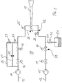
- Fig. 1 is the wiring diagram of a preferred embodiment of the device reproduced according to the invention.
- the fuel system 10 of the burner 11 (with Burner lance, nozzles and the like) of a gas turbine comprises two feed lines 12 and 13.
- the burner 11 is supplied with liquid fuel via the first feed line 12 fed.
- a pump 15 is provided in the first feed line.
- Behind the Pump 15 are in the first feed line 12 in a manner known per se Quick shut-off valve 17 and a control valve 19 for controlling the fuel volume flow arranged.
- the control valve 19 also marks in the feeder line 12 an interruption point 33, at which the fuel flow when the gas turbine is switched off is interrupted.
- the feed line 12 runs behind the control valve 19 via a (optionally available) sector valve 28 to the burner 11 or the (not shown) Fuel lance.
- the second feeder line 13 can now advantageously be used to rinse the first feeder line 12 or the fuel system 10 are used. There are two modifications provided: on the one hand, the two feeder lines 12 are shortly before the burner 11 and 13 connected to each other by a connecting line 26 through a check valve 27 (or valve) can be interrupted.
- bypass lines 20, 21 are equipped with orifices, one of which is orifice 22 for the bypass line 21, shown in Fig. 1.
- aperture (s) 22 are in the bypass lines predefined volume flows are specified, each for low pressure flushing and for High pressure rinsing are needed.
- the aperture 22 in the bypass line 21 has a relative small opening width and generates a low volume flow for the low pressure flushing process is used.
- the opening cross section in the bypass line 20 is in contrast larger. The correspondingly higher volume flow takes place during the high pressure flushing process Use.
- Another modification relates to an additional outlet in the first feed line 12. This outlet is behind the break point 33 by an outgoing Drainage line 29 formed, which via a drainage valve 30 to a leakage oil tank 31st leads in which the flushed out fuel is collected.
- the rinsing process according to the invention can be carried out in a device according to FIG. 1 will be explained with reference to the timing diagrams shown in FIG. 2.
- the curve A shows the fuel-air ratio that occurs during purging in the combustion chamber.
- Curve B shows the volume flow of the auxiliary or Flushing medium.
- Curve C shows the volume flow in the drainage line 29.
- Curve D (solid) is the extinguishing limit curve for the fuel-air ratio.
- the curve E (solid) shows the rotor speed of the gas turbine.
- the curves F, G, H, I and K show the switch position (open-closed) of the corresponding one Valves 24, 23, 30, 28 and 19.
- the flushing process begins at time t0 when the gas turbine, the The rotor speed then begins to decrease continuously according to curve E. At the same time, by closing the control valve 19 at the interruption point 33 the supply of liquid fuel is interrupted (curve K). Immediately after the The gas turbine is switched off (time t1) by opening the (for reasons of volume minimization check valve arranged as close as possible to the fuel lances) 27 (or valve) in the connecting line 26 that is under (low) pressure Flushing medium fed into the switched off fuel system (curve B between the times t1 and t3). The fuel in the affected lines is the flushing medium displaces and escapes into the combustion chamber, where it is either from the combustion chamber air transported or via the drainage systems and into the fuel tank is promoted back.
- the duration of the low pressure flushing process (t1-t2 or t1-t3) should be selected so that the Most of the fuel with very low momentum is removed from the fuel nozzles becomes. Only small residual amounts of fuel in the lance's dead water spaces or as a film on the material surfaces because of the low volume flows associated small shear forces remain.
- the parallel injection of water into the lances can or burner 11 via the feeder lines 13 by closing one or more Valves in the water and oil path, the so-called sector valves 25, 28, are prevented become. This makes it possible to meter the flushing medium flow or flushing water flow exactly and use all water to rinse the affected pipe sections.
- two switchable bypass lines 20, 21 with corresponding flow-restricting orifices (22) are preferably used to set the two defined volume flows during flushing.
- control valves or volume accumulators at defined pressure levels or extra pumps with adjustable volume flow.
- inert gases such as N 2 or CO 2 are also suitable as the flushing medium.
Landscapes
- Engineering & Computer Science (AREA)
- Chemical & Material Sciences (AREA)
- Combustion & Propulsion (AREA)
- Mechanical Engineering (AREA)
- General Engineering & Computer Science (AREA)
- Aviation & Aerospace Engineering (AREA)
- Feeding And Controlling Fuel (AREA)
- Nozzles For Spraying Of Liquid Fuel (AREA)
Abstract
Description
- Fig. 1
- das Leitungsschema eines bevorzugten Ausführungsbeispiels der Vorrichtung nach der Erfindung; und
- Fig. 2
- das Ablaufschema für einen Spülvorgang mit einer Vorrichtung nach Fig. 1 gemäss einem bevorzugten Ausführungsbeispiels des erfindungsgemässen Verfahrens.
- es handelt sich um ein sehr einfaches System
- es werden keine aufwendig konstruierten Brennstoffdüsen verwendet
- Verfahren und System sind sehr kostengünstig
- das System hat eine hohe Verfügbarkeit
- die Brennstoffsysteme befinden sich nach jedem Abstellen der Gasturbine in einem definiert ungefährlichen Zustand
- es besteht ein hohes Mass an Sicherheit bezüglich Nachzündungen von Brennstoff
- es besteht ein hohes Mass an Sicherheit bezüglich Verkoken von Brennstoff.
- 10
- Brennstoffsystem
- 11
- Brenner
- 12,13
- Zubringerleitung
- 14,15
- Pumpe
- 16,17
- Schnellabschaltventil
- 18,19
- Steuerventil
- 20,21
- Bypassleitung
- 22
- Blende
- 23,24
- Spülventil
- 25,28
- Sektorventil
- 26
- Verbindungsleitung
- 27
- Rückschlagventil (oder Ventil)
- 29
- Drainageleitung
- 30
- Drainageventil
- 31
- Leckageöltank
- 32
- Einspeisepunkt
- 33
- Unterbrechungsstelle
- A-K
- Kurve
- t0,..,t6
- Zeitpunkt
Claims (17)
- Verfahren zum sicheren Entfernen von Flüssigbrennstoff aus dem Brennstoffsystem (10) einer Gasturbine nach dem Abstellen derselben, bei welchem Brennstoffsystem (10) im Normalbetrieb der Gasturbine Flüssigbrennstoff über wenigstens eine erste Zubringerleitung (12) einem Brenner (11) zugeführt und dort über Brennstoffdüsen in eine Brennkammer eingedüst wird, dadurch gekennzeichnet, dass der Flüssigbrennstoff unter Verwendung eines inerten Hilfsmediums aus dem Brennstoffsystem (10) herausgespült wird.
- Verfahren nach Anspruch 1, dadurch gekennzeichnet, dass mit dem Abschalten der Gasturbine die Zufuhr von Flüssigbrennstoff über die erste Zubringerleitung (12) an einer Unterbrechungsstelle (33) in der ersten Zubringerleitung (12) unterbrochen wird, und dass das Hilfsmedium über eine zweite Zubringerleitung (13) an einem zwischen der Unterbrechungsstelle (33) und dem Brenner (11) befindlichen Einspeisepunkt (32) in die erste Zubringerleitung (12) eingespeist wird.
- Verfahren nach Anspruch 2, dadurch gekennzeichnet, dass in einem ersten Schritt mittels des am Einspeisepunkt (32) eingespeisten Hilfsmediums der zwischen Einspeisepunkt (32) und Brennstoffdüsen im Brennstoffsystem (10) befindliche Flüssigbrennstoff über die Brennstoffdüsen in die Brennkammer gespült wird, und dass in einem zweiten Schritt Flüssigbrennstoff, welcher sich in Strömungsrichtung vor dem Einspeisepunkt (32) in der ersten Zubringerleitung (32) befindet, mittels des am Einspeisepunkt (32) eingespeisten Hilfsmediums über einen separaten Auslass (29, 30, 31) aus der ersten Zubringerleitung (32) herausgespült wird.
- Verfahren nach Anspruch 3, dadurch gekennzeichnet, dass innerhalb des ersten Schrittes in einem ersten Niederdruckspülvorgang der grösste Teil des Flüssigbrennstoffs in die Brennkammer entleert wird, wobei das Hilfsmedium den Flüssigbrennstoff aus den betroffenen Leitungen verdrängt und nur Restmengen des Flüssigbrennstoffes, insbesondere in Form von Oberflächenfilmen, übrigbleiben, und dass in einem zweiten Hochdruckspülvorgang die verbliebenen Restmengen des Flüssigbrennstoffes entfernt werden.
- Verfahren nach Anspruch 4, dadurch gekennzeichnet, dass für den Niederdruckspülvorgang und den Hochdruckspülvorgang jeweils ein definierter Volumenstrom des Hilfsmediums verwendet wird, wobei der Volumenstrom beim Hochdruckspülvorgang grösser ist, als der Volumenstrom beim Niederdruckspülvorgang.
- Verfahren nach Anspruch einem der Ansprüche 4 und 5, dadurch gekennzeichnet, dass während des Niederdruckspülvorgangs Luft durch die Brennkammer geschickt und das Verhältnis von Brennstoff zu Luft in der Brennkammer unter der Lösch- bzw. mageren Zündgrenze gehalten wird.
- Verfahren nach Anspruch 6, dadurch gekennzeichnet, dass zum Einspeisen der Luft in die Brennkammer die Auslaufphase der Gasturbine benutzt wird.
- Verfahren nach Anspruch 6, dadurch gekennzeichnet, dass zum Einspeisen der Luft in die Brennkammer die Gasturbine mit eingeschalteter Anfahrvorrichtung, vorzugsweise bei einer definierten Ventilierungsdrehzahl, betrieben wird.
- Verfahren nach einem der Ansprüche 2 bis 8, dadurch gekennzeichnet, dass dem Brennstoffsystem (10) ein Wassereinspritzsystem zum Einspritzen von Wasser in die Verbrennungszone parallel geschaltet ist, und dass die Zubringerleitung (13) des Wassereinspritzsystems als zweite Zubringerleitung verwendet wird.
- Verfahren nach einem der Ansprüche 1 bis 9, dadurch gekennzeichnet, dass als inertes Hilfsmedium Wasser verwendet wird.
- Verfahren nach einem der Ansprüche 1 bis 9, dadurch gekennzeichnet, dass als inertes Hilfsmedium ein inertes Gas, insbesondere N2 oder CO2, verwendet wird.
- Vorrichtung zur Durchführung des Verfahrens nach einem der Ansprüche 1 bis 11, umfassend ein Brennstoffsystem (10) für eine Gasturbine mit wenigstens einer ersten Zubringerleitung (12), über welche der Flüssigbrennstoff zum Brenner (11) der Gasturbine geleitet und in die Brennkammer eingedüst wird, dadurch gekennzeichnet, dass eine zweite Zubringerleitung (13) vorgesehen ist, welche an einem Einspeisepunkt (32) mit der ersten Zubringerleitung (12) verbindbar ist.
- Vorrichtung nach Anspruch 12, dadurch gekennzeichnet, dass die zweite Zubringerleitung (13) die Zubringerleitung eines Wassereinspritzsystems ist, durch welches Wasser in die Brennkammer eingedüst werden kann, dass die zweite Zubringerleitung (13) über eine Verbindungsleitung (26) mit dem Einspeisepunkt (32) an der ersten Zubringerleitung (12) verbunden ist, und in der Verbindungsleitung (26) Mittel (27) zum Abschalten der Verbindungsleitung (26) angeordnet sind.
- Vorrichtung nach Anspruch 13, dadurch gekennzeichnet, dass die Abschaltmittel ein Rückschlagventil (27) oder Ventil umfassen.
- Vorrichtung nach einem der Ansprüche 13 und 14, dadurch gekennzeichnet, dass an der zweiten Zubringerleitung (13) zwei Bypassleitungen (20, 21) angeordnet sind, welche wahlweise in die zweite Zubringerleitung (13) einschaltbar sind, und jeweils Mittel (22) zur Festlegung eines definierten Volumenstromes enthalten.
- Vorrichtung nach einem der Ansprüche 12 bis 15, dadurch gekennzeichnet, dass in Strömungsrichtung vor dem Einspeisepunkt (32) an der ersten Zubringerleitung (12) ein separater Auslass (29, 30, 31) vorgesehen ist.
- Vorrichtung nach Anspruch 16, dadurch gekennzeichnet, dass der Auslass eine Drainageleitung (29) mit einem Drainageventil (30) umfasst, welche Drainageleitung (29) zu einem Leckageöltank (31) führt.
Priority Applications (5)
| Application Number | Priority Date | Filing Date | Title |
|---|---|---|---|
| EP98810157A EP0939220B1 (de) | 1998-02-26 | 1998-02-26 | Verfahren zum sicheren Entfernen von Flüssigbrennstoff aus dem Brennstoffsystem einer Gasturbine sowie Vorrichtung zur Durchführung des Verfahrens |
| DE59810159T DE59810159D1 (de) | 1998-02-26 | 1998-02-26 | Verfahren zum sicheren Entfernen von Flüssigbrennstoff aus dem Brennstoffsystem einer Gasturbine sowie Vorrichtung zur Durchführung des Verfahrens |
| US09/255,710 US6256975B1 (en) | 1998-02-26 | 1999-02-23 | Method for reliably removing liquid fuel from the fuel system of a gas turbine, and a device for carrying out the method |
| CN99102282A CN1115474C (zh) | 1998-02-26 | 1999-02-25 | 从燃气轮机燃料系统中可靠地排出液体燃料的方法和装置 |
| JP04828499A JP4253389B2 (ja) | 1998-02-26 | 1999-02-25 | ガスタービンの燃料系から液体燃料を確実に除去する方法及びこの方法を実施するための装置 |
Applications Claiming Priority (1)
| Application Number | Priority Date | Filing Date | Title |
|---|---|---|---|
| EP98810157A EP0939220B1 (de) | 1998-02-26 | 1998-02-26 | Verfahren zum sicheren Entfernen von Flüssigbrennstoff aus dem Brennstoffsystem einer Gasturbine sowie Vorrichtung zur Durchführung des Verfahrens |
Publications (2)
| Publication Number | Publication Date |
|---|---|
| EP0939220A1 true EP0939220A1 (de) | 1999-09-01 |
| EP0939220B1 EP0939220B1 (de) | 2003-11-12 |
Family
ID=8235967
Family Applications (1)
| Application Number | Title | Priority Date | Filing Date |
|---|---|---|---|
| EP98810157A Expired - Lifetime EP0939220B1 (de) | 1998-02-26 | 1998-02-26 | Verfahren zum sicheren Entfernen von Flüssigbrennstoff aus dem Brennstoffsystem einer Gasturbine sowie Vorrichtung zur Durchführung des Verfahrens |
Country Status (5)
| Country | Link |
|---|---|
| US (1) | US6256975B1 (de) |
| EP (1) | EP0939220B1 (de) |
| JP (1) | JP4253389B2 (de) |
| CN (1) | CN1115474C (de) |
| DE (1) | DE59810159D1 (de) |
Cited By (12)
| Publication number | Priority date | Publication date | Assignee | Title |
|---|---|---|---|---|
| DE10002084A1 (de) * | 2000-01-19 | 2001-08-02 | Siemens Ag | Gas- und Dampfturbinenanlage |
| WO2002029225A1 (en) * | 2000-10-04 | 2002-04-11 | Capstone Turbine Corporation | Method of shutting-down a turbine engine and system for carrying out said method |
| EP2216529A1 (de) | 2009-02-06 | 2010-08-11 | Siemens Aktiengesellschaft | Verfahren zum Spülen eines Abschnitts eines Brennstoffsystems einer Gasturbine |
| WO2011026982A1 (en) * | 2009-09-07 | 2011-03-10 | Alstom Technology Ltd | Method for switching over a gas turbine burner operation from liquid to gas fuel and vice-versa |
| CN102654080A (zh) * | 2006-09-28 | 2012-09-05 | 三菱重工业株式会社 | 用于起动和停止燃气轮机的方法及设备 |
| RU2460894C1 (ru) * | 2008-06-09 | 2012-09-10 | Сименс Акциенгезелльшафт | Способ промывки топливной системы газовой турбины и соответствующая топливная система |
| CH704715A1 (de) * | 2011-03-22 | 2012-09-28 | Alstom Technology Ltd | Verfahren zum Betrieb einer Gasturbine mit einem nachgeschalteten Abhitzekessel. |
| FR2989736A1 (fr) * | 2012-04-18 | 2013-10-25 | Ge Energy Products France Snc | Procede de purge d'une turbine a gaz |
| EP1783347A3 (de) * | 2005-11-07 | 2014-05-07 | General Electric Company | Methode und Apparat für ein Stickstoffentlüftungssystem einer Gasturbine |
| WO2014195570A1 (en) * | 2013-06-03 | 2014-12-11 | Wärtsilä Finland Oy | Fuel system and method for operating a piston engine |
| WO2015086390A1 (de) * | 2013-12-09 | 2015-06-18 | Siemens Aktiengesellschaft | Gasturbine mit bypassleitung zur verbesserten brennstoffleitungsspülung sowie verfahren zum spülen einer gasturbine |
| US9371995B2 (en) | 2013-04-11 | 2016-06-21 | General Electric Company | Pulsed water flush of liquid fuel valves and combustion nozzles |
Families Citing this family (27)
| Publication number | Priority date | Publication date | Assignee | Title |
|---|---|---|---|---|
| EP1199453A3 (de) * | 1998-05-08 | 2003-01-22 | Mitsubishi Heavy Industries, Ltd. | Spülsystem für Brennstoffeinspritzdüsen einer Gasturbine |
| JP4335397B2 (ja) * | 2000-02-01 | 2009-09-30 | 三菱重工業株式会社 | ガスタービン燃料ガス漲装置 |
| US7296412B2 (en) * | 2003-12-30 | 2007-11-20 | General Electric Company | Nitrogen purge for combustion turbine liquid fuel system |
| JP2008525527A (ja) * | 2004-12-27 | 2008-07-17 | キング・ファーマシューティカルズ・リサーチ・アンド・デベロプメント・インコーポレイティッド | 脱酸素剤を有していてもよい酸素不浸透性包装の安定化甲状腺ホルモン組成物及び甲状腺ホルモン医薬組成物保管のためのその方法 |
| US7721521B2 (en) * | 2005-11-07 | 2010-05-25 | General Electric Company | Methods and apparatus for a combustion turbine fuel recirculation system and nitrogen purge system |
| US7954310B2 (en) * | 2006-06-16 | 2011-06-07 | Siemens Energy, Inc. | Fuel oil bi-directional flow divider |
| US7617024B2 (en) * | 2006-09-22 | 2009-11-10 | Bell Helicopter Textron Inc. | Automatic heading control system for tiltrotor aircraft and helicopters |
| DE102007043626A1 (de) * | 2007-09-13 | 2009-03-19 | Rolls-Royce Deutschland Ltd & Co Kg | Gasturbinenmagerbrenner mit Kraftstoffdüse mit kontrollierter Kraftstoffinhomogenität |
| DE102008014744A1 (de) * | 2008-03-18 | 2009-09-24 | Rolls-Royce Deutschland Ltd & Co Kg | Gasturbinenbrenner für eine Gasturbine mit Spülmechanismus für eine Brennstoffdüse |
| FR2938048B1 (fr) * | 2008-11-06 | 2015-03-06 | Ge Energy Products France Snc | Systeme et procede de lavage et purge a l'eau du circuit combustible liquide d'une turbine |
| US20110100015A1 (en) * | 2009-11-05 | 2011-05-05 | General Electric Company | Gas turbine system to inhibit coke formation and methods of use |
| JP2012041897A (ja) * | 2010-08-20 | 2012-03-01 | Toyota Motor Corp | スターリングエンジンの制御装置 |
| US9188061B2 (en) * | 2011-10-24 | 2015-11-17 | General Electric Company | System for turbine combustor fuel assembly |
| US9261023B2 (en) | 2012-01-04 | 2016-02-16 | General Electric Company | Systems and methods for monitoring fluid separation and/or monitoring the health of a valve |
| US8991190B2 (en) * | 2012-01-31 | 2015-03-31 | General Electric Company | Fuel nozzle staging with water flowing prior to fuel in a main fuel circuit during start-up |
| CN102777270A (zh) * | 2012-08-08 | 2012-11-14 | 长沙众强科技开发有限公司 | 燃气发电机组供给管道剩余燃料燃烧的控制系统及方法 |
| FR2994943B1 (fr) * | 2012-08-30 | 2014-09-12 | Turbomeca | Procede de vidange et collecteur de purge de circuit de carburation d'un helicoptere |
| US9909499B2 (en) * | 2014-04-04 | 2018-03-06 | General Electric Company | Fuel drainage and purge system and method |
| US10012148B2 (en) * | 2014-05-23 | 2018-07-03 | General Electric Company | Method of purging a combustor |
| EP2975240B1 (de) | 2014-07-18 | 2019-11-13 | United Technologies Corporation | Selbstreinigendes brennstoffdüsensystem für einen gasturbinenmotor |
| US20160348594A1 (en) * | 2014-12-02 | 2016-12-01 | General Electric Company | Fuel purge system and method of purging |
| FR3039591B1 (fr) * | 2015-07-31 | 2017-08-25 | Snecma | Isolation d'un reservoir de turbomachine d'aeronef en cas d'incendie par fermeture d'une vanne sensible a la liberation d'un agent extincteur |
| US10247110B2 (en) * | 2015-09-23 | 2019-04-02 | General Electric Company | Method and system for reliable gas to liquid transfer |
| JP6779097B2 (ja) * | 2016-10-24 | 2020-11-04 | 三菱パワー株式会社 | ガスタービン燃焼器及びその運転方法 |
| EP3963191B8 (de) * | 2019-05-30 | 2025-06-18 | Siemens Energy Global GmbH & Co. KG | Wassereinspritzung in eine gasturbine zur reduzierung von emissionen |
| EP4015395B1 (de) * | 2020-12-16 | 2024-10-09 | Airbus Operations, S.L.U. | Flugzeug und verfahren zum betreiben eines flugzeugs mit einer lufttrennungsvorrichtung |
| WO2025264222A1 (en) * | 2024-06-20 | 2025-12-26 | Ge Vernova Infrastructure Technology Llc | Fuel flush system and method |
Citations (7)
| Publication number | Priority date | Publication date | Assignee | Title |
|---|---|---|---|---|
| US2015995A (en) * | 1934-01-13 | 1935-10-01 | Boeing Co | Fire preventing and extinguishing system for aircraft |
| US2038998A (en) * | 1932-11-12 | 1936-04-28 | Jr John Hays Hammond | Gas tank discharger for airplanes |
| US3901025A (en) * | 1974-02-01 | 1975-08-26 | Piper Aircraft Corp | Aircraft engine fuel system |
| US4032091A (en) * | 1976-03-05 | 1977-06-28 | Thomas J. Reddy, Trustee | Fuel line evacuation system |
| US4391241A (en) * | 1979-12-21 | 1983-07-05 | Nippondenso Co., Ltd. | Stopping device for engine supplied with fuel by fuel injection pump |
| JPS6017626A (ja) * | 1983-07-08 | 1985-01-29 | Hitachi Ltd | 燃料パ−ジ法 |
| EP0724115A2 (de) * | 1995-01-24 | 1996-07-31 | Delavan Inc | Reinigungsverfahren für Gasturbinen-Einspritzdüse |
Family Cites Families (4)
| Publication number | Priority date | Publication date | Assignee | Title |
|---|---|---|---|---|
| SE394902B (sv) * | 1975-10-28 | 1977-07-18 | Stal Laval Turbin Ab | Brenslespridare for brennkammare |
| US5339845A (en) * | 1993-07-26 | 1994-08-23 | Fuel Systems Textron, Inc. | Cleaning apparatus and method for fuel and other passages |
| US5809771A (en) * | 1996-01-19 | 1998-09-22 | Woodward Governor Company | Aircraft engine fuel system |
| US6125624A (en) * | 1998-04-17 | 2000-10-03 | Pratt & Whitney Canada Corp. | Anti-coking fuel injector purging device |
-
1998
- 1998-02-26 DE DE59810159T patent/DE59810159D1/de not_active Expired - Lifetime
- 1998-02-26 EP EP98810157A patent/EP0939220B1/de not_active Expired - Lifetime
-
1999
- 1999-02-23 US US09/255,710 patent/US6256975B1/en not_active Expired - Lifetime
- 1999-02-25 CN CN99102282A patent/CN1115474C/zh not_active Expired - Fee Related
- 1999-02-25 JP JP04828499A patent/JP4253389B2/ja not_active Expired - Fee Related
Patent Citations (7)
| Publication number | Priority date | Publication date | Assignee | Title |
|---|---|---|---|---|
| US2038998A (en) * | 1932-11-12 | 1936-04-28 | Jr John Hays Hammond | Gas tank discharger for airplanes |
| US2015995A (en) * | 1934-01-13 | 1935-10-01 | Boeing Co | Fire preventing and extinguishing system for aircraft |
| US3901025A (en) * | 1974-02-01 | 1975-08-26 | Piper Aircraft Corp | Aircraft engine fuel system |
| US4032091A (en) * | 1976-03-05 | 1977-06-28 | Thomas J. Reddy, Trustee | Fuel line evacuation system |
| US4391241A (en) * | 1979-12-21 | 1983-07-05 | Nippondenso Co., Ltd. | Stopping device for engine supplied with fuel by fuel injection pump |
| JPS6017626A (ja) * | 1983-07-08 | 1985-01-29 | Hitachi Ltd | 燃料パ−ジ法 |
| EP0724115A2 (de) * | 1995-01-24 | 1996-07-31 | Delavan Inc | Reinigungsverfahren für Gasturbinen-Einspritzdüse |
Non-Patent Citations (1)
| Title |
|---|
| PATENT ABSTRACTS OF JAPAN vol. 009, no. 135 (M - 386) 11 June 1985 (1985-06-11) * |
Cited By (20)
| Publication number | Priority date | Publication date | Assignee | Title |
|---|---|---|---|---|
| DE10002084C2 (de) * | 2000-01-19 | 2001-11-08 | Siemens Ag | Gas- und Dampfturbinenanlage |
| US6889506B2 (en) | 2000-01-19 | 2005-05-10 | Siemens Aktiengesellschaft | Gas and steam turbine installation |
| DE10002084A1 (de) * | 2000-01-19 | 2001-08-02 | Siemens Ag | Gas- und Dampfturbinenanlage |
| WO2002029225A1 (en) * | 2000-10-04 | 2002-04-11 | Capstone Turbine Corporation | Method of shutting-down a turbine engine and system for carrying out said method |
| EP1783347A3 (de) * | 2005-11-07 | 2014-05-07 | General Electric Company | Methode und Apparat für ein Stickstoffentlüftungssystem einer Gasturbine |
| CN102654080A (zh) * | 2006-09-28 | 2012-09-05 | 三菱重工业株式会社 | 用于起动和停止燃气轮机的方法及设备 |
| CN102654080B (zh) * | 2006-09-28 | 2014-12-17 | 三菱重工业株式会社 | 用于起动和停止燃气轮机的方法及设备 |
| RU2460894C1 (ru) * | 2008-06-09 | 2012-09-10 | Сименс Акциенгезелльшафт | Способ промывки топливной системы газовой турбины и соответствующая топливная система |
| US9175606B2 (en) | 2008-06-09 | 2015-11-03 | Siemens Aktiengesellschaft | Method for rinsing a fuel system of a gas turbine and associated fuel system |
| WO2010089204A1 (de) * | 2009-02-06 | 2010-08-12 | Siemens Aktiengesellschaft | Verfahren zum spülen eines abschnitts eines brennstoffsystems einer gasturbine |
| EP2216529A1 (de) | 2009-02-06 | 2010-08-11 | Siemens Aktiengesellschaft | Verfahren zum Spülen eines Abschnitts eines Brennstoffsystems einer Gasturbine |
| EP2299091A1 (de) * | 2009-09-07 | 2011-03-23 | Alstom Technology Ltd | Verfahren zum Umschalten des Betriebes eines Gasturbinenbrenners von flüssigen auf gasförmigen Brennstoff und umgekehrt. |
| WO2011026982A1 (en) * | 2009-09-07 | 2011-03-10 | Alstom Technology Ltd | Method for switching over a gas turbine burner operation from liquid to gas fuel and vice-versa |
| CH704715A1 (de) * | 2011-03-22 | 2012-09-28 | Alstom Technology Ltd | Verfahren zum Betrieb einer Gasturbine mit einem nachgeschalteten Abhitzekessel. |
| FR2989736A1 (fr) * | 2012-04-18 | 2013-10-25 | Ge Energy Products France Snc | Procede de purge d'une turbine a gaz |
| US9371995B2 (en) | 2013-04-11 | 2016-06-21 | General Electric Company | Pulsed water flush of liquid fuel valves and combustion nozzles |
| WO2014195570A1 (en) * | 2013-06-03 | 2014-12-11 | Wärtsilä Finland Oy | Fuel system and method for operating a piston engine |
| US9850864B2 (en) | 2013-06-03 | 2017-12-26 | Wärtsilä Finland Oy | Fuel system and method for operating a piston engine |
| WO2015086390A1 (de) * | 2013-12-09 | 2015-06-18 | Siemens Aktiengesellschaft | Gasturbine mit bypassleitung zur verbesserten brennstoffleitungsspülung sowie verfahren zum spülen einer gasturbine |
| US10184351B2 (en) | 2013-12-09 | 2019-01-22 | Siemens Aktiengesellschaft | Gas turbine with a bypass line for improved fuel line flushing, and method for flushing a gas turbine |
Also Published As
| Publication number | Publication date |
|---|---|
| JP2000064855A (ja) | 2000-02-29 |
| US6256975B1 (en) | 2001-07-10 |
| EP0939220B1 (de) | 2003-11-12 |
| CN1115474C (zh) | 2003-07-23 |
| CN1227310A (zh) | 1999-09-01 |
| JP4253389B2 (ja) | 2009-04-08 |
| DE59810159D1 (de) | 2003-12-18 |
Similar Documents
| Publication | Publication Date | Title |
|---|---|---|
| EP0939220A1 (de) | Verfahren zum sicheren Entfernen von Flüssigbrennstoff aus dem Brennstoffsystem einer Gasturbine sowie Vorrichtung zur Durchführung des Verfahrens | |
| DE112015002636B4 (de) | Verfahren zum Spülen eines Kraftstoffkanals, Spülvorrichtung zur Ausführung des Verfahrens und Gasturbineninstallation mit der Spülvorrichtung | |
| DE19903770B4 (de) | Vergasungsbrenner für einen Gasturbinenmotor | |
| DE112009002724B4 (de) | System und Verfahren zum Waschen und Spülen der Flüssigbrennstoffleitung einer Turbine mit Wasser | |
| EP2304205B1 (de) | Verfahren zum spülen eines brennstoffsystems einer gasturbine und zugehöriges brennstoffsystem | |
| EP2394039B1 (de) | Verfahren zum spülen eines abschnitts eines brennstoffsystems einer gasturbine | |
| DE3916410A1 (de) | Brennstoffsystem fuer ein gasturbinentriebwerk | |
| EP2270319A1 (de) | Verfahren und Vorrichtung zur Reinigung von Partikelfiltern in Abgasanlage von Verbrennungsmotoren | |
| DE60019887T2 (de) | Doppelöffnungbypasssystem für Gasturbine mit Zweibrennstoffdüse | |
| DE102004057985A1 (de) | Gasturbinenverbrennungsvorrichtung | |
| DE102020116222A1 (de) | Gasversorgungssystem für einen Gasmotor oder Dual-Fuel-Motor und Verfahren zum Betreiben desselben | |
| DE3401143A1 (de) | Verfahren und vorrichtung zur einbringung eines fluessigen mediums in den arbeitsraum einer verbrennungskraftmaschine | |
| DE102012206979A1 (de) | Kraftstoffeinspritzsystem für eine Brennkraftmaschine und Verfahren zum Betreiben des Kraftstoffeinspritzsystems | |
| DE4211681C2 (de) | Verfahren zum Steuern des Abbrennens eines Brenngases | |
| DE3046876C2 (de) | Brennkraftmaschine mit Aufladung durch Abgasturbolader | |
| EP2987978A1 (de) | Antriebseinheit und verfahren zum betrieb einer antriebseinheit | |
| DE102009056026B4 (de) | Verfahren zum Betreiben einer Brennkraftmaschine eines Kraftfahrzeugs | |
| DE10240833A1 (de) | Verfahren zum Verringern von Abgasemissionen einer Brennkraftmaschine | |
| DE10148221A1 (de) | Verfahren, Computerprogramm sowie Steuer- und/oder Regelgerät zum Betreiben einer Brennkraftmaschine, sowie Brennkraftmaschine | |
| DE102007015311A1 (de) | Verfahren zum Betrieb einer Gasturbine | |
| EP1172545B1 (de) | Zündsystem für Brennkammern in Raketentriebwerken | |
| DE3046875A1 (de) | "brennkraftmaschine" | |
| DE2910464A1 (de) | Brennstoffinjektor fuer ein gasturbinentriebwerk | |
| DE102011076154B4 (de) | Partikelfilter zur Reinigung eines Abgasstroms | |
| EP1934528B1 (de) | Verfahren und vorrichtung zur überwachung sich bildender ablagerungen von feststoffteilchen, insbesondere in einer brennstoffleitung sowie in den brennstoffventilen einer gasturbine |
Legal Events
| Date | Code | Title | Description |
|---|---|---|---|
| PUAI | Public reference made under article 153(3) epc to a published international application that has entered the european phase |
Free format text: ORIGINAL CODE: 0009012 |
|
| AK | Designated contracting states |
Kind code of ref document: A1 Designated state(s): DE FR GB |
|
| AX | Request for extension of the european patent |
Free format text: AL;LT;LV;MK;RO;SI |
|
| 17P | Request for examination filed |
Effective date: 20000216 |
|
| AKX | Designation fees paid |
Free format text: DE FR GB |
|
| RAP1 | Party data changed (applicant data changed or rights of an application transferred) |
Owner name: ALSTOM |
|
| RAP1 | Party data changed (applicant data changed or rights of an application transferred) |
Owner name: ALSTOM (SWITZERLAND) LTD |
|
| 17Q | First examination report despatched |
Effective date: 20021018 |
|
| GRAH | Despatch of communication of intention to grant a patent |
Free format text: ORIGINAL CODE: EPIDOS IGRA |
|
| GRAS | Grant fee paid |
Free format text: ORIGINAL CODE: EPIDOSNIGR3 |
|
| GRAA | (expected) grant |
Free format text: ORIGINAL CODE: 0009210 |
|
| AK | Designated contracting states |
Kind code of ref document: B1 Designated state(s): DE FR GB |
|
| REG | Reference to a national code |
Ref country code: GB Ref legal event code: FG4D Free format text: NOT ENGLISH |
|
| REF | Corresponds to: |
Ref document number: 59810159 Country of ref document: DE Date of ref document: 20031218 Kind code of ref document: P |
|
| RAP2 | Party data changed (patent owner data changed or rights of a patent transferred) |
Owner name: ALSTOM TECHNOLOGY LTD |
|
| GBT | Gb: translation of ep patent filed (gb section 77(6)(a)/1977) |
Effective date: 20040128 |
|
| REG | Reference to a national code |
Ref country code: GB Ref legal event code: 732E |
|
| ET | Fr: translation filed | ||
| PLBE | No opposition filed within time limit |
Free format text: ORIGINAL CODE: 0009261 |
|
| STAA | Information on the status of an ep patent application or granted ep patent |
Free format text: STATUS: NO OPPOSITION FILED WITHIN TIME LIMIT |
|
| 26N | No opposition filed |
Effective date: 20040813 |
|
| REG | Reference to a national code |
Ref country code: FR Ref legal event code: TP |
|
| REG | Reference to a national code |
Ref country code: FR Ref legal event code: PLFP Year of fee payment: 19 |
|
| REG | Reference to a national code |
Ref country code: DE Ref legal event code: R082 Ref document number: 59810159 Country of ref document: DE Representative=s name: ROESLER, UWE, DIPL.-PHYS.UNIV., DE Ref country code: DE Ref legal event code: R081 Ref document number: 59810159 Country of ref document: DE Owner name: ANSALDO ENERGIA IP UK LIMITED, GB Free format text: FORMER OWNER: ALSTOM TECHNOLOGY LTD., BADEN, CH Ref country code: DE Ref legal event code: R081 Ref document number: 59810159 Country of ref document: DE Owner name: GENERAL ELECTRIC TECHNOLOGY GMBH, CH Free format text: FORMER OWNER: ALSTOM TECHNOLOGY LTD., BADEN, CH |
|
| REG | Reference to a national code |
Ref country code: FR Ref legal event code: CD Owner name: ALSTOM TECHNOLOGY LTD, CH Effective date: 20161110 |
|
| REG | Reference to a national code |
Ref country code: FR Ref legal event code: PLFP Year of fee payment: 20 |
|
| PGFP | Annual fee paid to national office [announced via postgrant information from national office to epo] |
Ref country code: FR Payment date: 20170217 Year of fee payment: 20 Ref country code: DE Payment date: 20170217 Year of fee payment: 20 |
|
| PGFP | Annual fee paid to national office [announced via postgrant information from national office to epo] |
Ref country code: GB Payment date: 20170216 Year of fee payment: 20 |
|
| REG | Reference to a national code |
Ref country code: DE Ref legal event code: R082 Ref document number: 59810159 Country of ref document: DE Representative=s name: ROESLER, UWE, DIPL.-PHYS.UNIV., DE Ref country code: DE Ref legal event code: R081 Ref document number: 59810159 Country of ref document: DE Owner name: ANSALDO ENERGIA IP UK LIMITED, GB Free format text: FORMER OWNER: GENERAL ELECTRIC TECHNOLOGY GMBH, BADEN, CH |
|
| REG | Reference to a national code |
Ref country code: GB Ref legal event code: 732E Free format text: REGISTERED BETWEEN 20170824 AND 20170830 |
|
| REG | Reference to a national code |
Ref country code: FR Ref legal event code: TP Owner name: ANSALDO ENERGIA IP UK LIMITED, GB Effective date: 20171221 |
|
| REG | Reference to a national code |
Ref country code: DE Ref legal event code: R071 Ref document number: 59810159 Country of ref document: DE |
|
| REG | Reference to a national code |
Ref country code: GB Ref legal event code: PE20 Expiry date: 20180225 |
|
| PG25 | Lapsed in a contracting state [announced via postgrant information from national office to epo] |
Ref country code: GB Free format text: LAPSE BECAUSE OF EXPIRATION OF PROTECTION Effective date: 20180225 |