EP0939257A2 - Radialwellendichtung - Google Patents
Radialwellendichtung Download PDFInfo
- Publication number
- EP0939257A2 EP0939257A2 EP99103640A EP99103640A EP0939257A2 EP 0939257 A2 EP0939257 A2 EP 0939257A2 EP 99103640 A EP99103640 A EP 99103640A EP 99103640 A EP99103640 A EP 99103640A EP 0939257 A2 EP0939257 A2 EP 0939257A2
- Authority
- EP
- European Patent Office
- Prior art keywords
- ribs
- oil
- helical
- flat surface
- shaft
- Prior art date
- Legal status (The legal status is an assumption and is not a legal conclusion. Google has not performed a legal analysis and makes no representation as to the accuracy of the status listed.)
- Withdrawn
Links
- 238000005086 pumping Methods 0.000 claims abstract description 128
- YAFQFNOUYXZVPZ-UHFFFAOYSA-N liproxstatin-1 Chemical compound ClC1=CC=CC(CNC=2C3(CCNCC3)NC3=CC=CC=C3N=2)=C1 YAFQFNOUYXZVPZ-UHFFFAOYSA-N 0.000 claims description 37
- 238000007789 sealing Methods 0.000 abstract description 18
- 238000005299 abrasion Methods 0.000 description 15
- 239000012530 fluid Substances 0.000 description 12
- 230000002093 peripheral effect Effects 0.000 description 7
- 150000001875 compounds Chemical class 0.000 description 3
- 230000003247 decreasing effect Effects 0.000 description 3
- 239000000428 dust Substances 0.000 description 3
- 239000000945 filler Substances 0.000 description 3
- 239000000463 material Substances 0.000 description 3
- 239000002131 composite material Substances 0.000 description 2
- 230000007547 defect Effects 0.000 description 2
- 238000011109 contamination Methods 0.000 description 1
- 230000000694 effects Effects 0.000 description 1
- 238000000034 method Methods 0.000 description 1
- 230000003068 static effect Effects 0.000 description 1
Images





Classifications
-
- F—MECHANICAL ENGINEERING; LIGHTING; HEATING; WEAPONS; BLASTING
- F16—ENGINEERING ELEMENTS AND UNITS; GENERAL MEASURES FOR PRODUCING AND MAINTAINING EFFECTIVE FUNCTIONING OF MACHINES OR INSTALLATIONS; THERMAL INSULATION IN GENERAL
- F16J—PISTONS; CYLINDERS; SEALINGS
- F16J15/00—Sealings
- F16J15/16—Sealings between relatively-moving surfaces
- F16J15/32—Sealings between relatively-moving surfaces with elastic sealings, e.g. O-rings
- F16J15/3244—Sealings between relatively-moving surfaces with elastic sealings, e.g. O-rings with hydrodynamic pumping action
Definitions
- the present invention relates to oil seals for establishing a seal between relatively movable shaft and housing. More particularly, the present invention relates to lip-type oil seals having hydrodynamic pumping means, which is used in an automobile or in a general industrial machinery.
- an oil seal having helical pumping ribs 52 at around a tip portion of a seal lip 51 to improve seal functions.
- the pumping ribs provide oil seals with a pumping function to pump fluid to be sealed toward fluid side.
- This type of oil seals has a sharp edge 53 at a tip of the seal lip 51, and the helical pumping ribs 52 starts from the sharp edge 53.
- the sharp edge 53 tends to be abraded comparatively rapidly by sliding on a member to be sealed such as a shaft (not shown in FIG.15).
- Japan unexamined laid open patent 7-301339 discloses an oil seal having, in the seal lip 101, a third frustoconical surface (so called a "flat" surface) 106 between a frustoconical air-side surface 103 and a frustoconical oil-side surface 102 ( as is shown in FIG.16) to avoid such a defect as described above.
- a third frustoconical surface so called a "flat" surface
- edge line 104 and 107 which is a juncture line between the flat surface 106 and the frustoconical oil-side surface 102, and between the flat surface 106 and the frustoconical air-side surface 103, respectively as shown in FIG.16.
- the flat surface has a width W in actual size, which is a width in the direction of a central axis line 0 of the oil seal.
- the oil seal also has angles ⁇ , ⁇ , and ⁇ as is shown in FIG.16; the ⁇ , ⁇ and ⁇ is an angle between the central axis of the oil seal and the frustoconical oil-side surface 102, the frustoconical air-side surface 103, and the so-called flat surface 106, respectively.
- the patent of 7-301339 also discloses uniform helical grooves providing the seal lip with a pumping function pumping oil (or fluid, not shown in FIG.16) back from the air-side to the oil-side.
- the terms "oil-side” and “air-side” refer, respectively, to being situated closer to the oil-side A and the air-side B indicated in FIG.16.
- the oil seal also has a garter spring 105 placed in a groove formed on an outer periphery of the seal lip 101, and a rigid annular casing 108 which supports the seal lip 101 in the lower part of the oil seal, as is shown in FIG.16.
- the 7-301339 patent has such a wider projection area which is placed between a groove and an another adjacent groove, that a deformation of the groove is not so large at the time when the third frustoconical surface is fitted on a member (or shaft, not shown in FIG.16) to be sealed.
- This type of oil seals show sometimes some disadvantages such as some oil leakage from the oil-side A to the air-side B through a portion between the seal lip and the member (shaft) to be sealed, at the time of the state that there is no relative rotational movement between the seal lip and the member (shaft) to be sealed, because of the groove being usually little deformed to cause some apertures between the seal lip and the shaft.
- an object of the present invention is to provide an oil seal having a property not to be decreased in pumping function of the ribs at around the edge of the seal lip in its long use, and having an excellent sealing property even at the time there is no relative movement between the seal lip and the shaft, resulting an excellent sealing properties for a long period of time as well as at an initial stage in use.
- Another object of the present invention is to provide an oil seal having an improved wearability.
- a still another object of the present invention is to provide an oil seal having a static and dynamic sealing performance.
- a still another object of the present invention is to provide an oil seal having an improved hydrodynamic pumping function even at the time of the counter member to be sealed is counterrotated.
- a third annular substantially frustoconical (or flat) surface between a frustoconical air-side surface and a frustoconical oil-side surface of a seal lip and providing a plurality of helical pumping ribs on the third annular flat surface to pump back oil in the sliding portion of the seal lip, to the oil-side.
- the cross-sectional shape of each ribs provided on the third annular flat surface are similar to a triangular or bilge or mountainous shape in its cross section and the height of the ribs are uniformly controlled throughout its entire length.
- Each ribs is formed from the edge on the oil (or fluid) side to another edge on the air-side of the third annular flat surface with a predetermined crisscross angle ⁇ to an edge line, which is a juncture line between the third annular flat surface and the frustoconical oil-side surface. These first ribs are placed equally around the surface of the third surface.
- first ribs can be placed equally around the surface of the third surface with a predetermined crisscross angle (180° minus ⁇ or 180- ⁇ ) to the edge line, so as to prevent oil from leaking at the time of reverse revolution of the shaft.
- a predetermined crisscross angle 180° minus ⁇ or 180- ⁇
- first helical ribs mentioned above are designed to be deformed when the seal lip 1 is mounted on the shaft, so that the third surface having the first helical ribs is snugly fitted on the shaft to prevent oil from leaking through the portion between the shaft and the third surface at the time there is no relative movement between the shaft and the third annular flat surface.
- each second helical pumping ribs have a bilge type or a triangular type in cross section thereof. And the height and the width of the second pumping ribs, at least partially, progressively increases from the oil-side to the air-side.
- These second ribs are placed equally around the surface of the frustoconical air-side surface with a predetermined crisscross angle to an edge line, which is a juncture line of the third annular flat surface and the frustoconical air-side surface.
- a frustoconical oil-side surface 2 a frustoconical air-side surface 3, and a third annular substantially frustoconical (or flat) surface 4 placed between the frustoconical oil-side surface 2 and the frustoconical air-side surface 3 are provided in the tip (inner periphery) of the seal lip 1.
- annular edge lines 4a and 4b which are defined by the frustoconical oil-side surface 2 and the third flat surface 4, and, the frustoconical air-side surface 3 and the third flat surface 4, respectively.
- the diameter of the frustoconical oil-side surface 2 gradually increases from an air-side B to an oil-side A.
- the third annular flat surface 4 has a predetermined width W and slidably and sealingly contacts with a member (shaft) 21 to be sealed by the seal lip 1.
- a conventional garter spring 8 is mounted within a spring groove 7 formed on the outer periphery of the seal lip 1. There is also a conventional dust lip 9 to prevent from entering contamination from the air-side B.
- the flat surface 4 is shown like a frustoconical surface having a diameter thereof gradually increasing from the oil-side A to the air-side B.
- This configuration depends on the fact that the oil seal is not fitted on the member (shaft) 21, so the seal lip 1 is in a free state.
- the seal lip 1 is moved toward C axis around a support portion 5 , which is supported by a rigid annular casing (not shown), by the interference between the shaft 21 and the seal lip 1 in FIG. 1, thereby resulting a fully contact of the whole surface 4 with the shaft 21 to bring the frustoconical shape of the surface 4 into a cylindrical (or flat) shape.
- each preferable angle of ⁇ , ⁇ and ⁇ which are shown in FIG.1, are as follows.
- a preferable angle a between the central axis of the oil seal and the frustoconical oil-side surface 2 was in the range of about 40° to 60°
- a preferable angle ⁇ between the central axis of the oil seal and the frustoconical air-side surface 3 was in the range of about 15° to 30°
- a preferable angle ⁇ between the central axis of the oil seal and the third flat surface 4 was in the range of about 5° to 15° , as shown in FIG.1.
- the width W of the third flat surface 4 in the direction of the central axis of the oil seal was preferably about 0.1 mm to 1.5 mm in actual size.
- a width of the third flat surface can be made wider with increasing an inside diameter of a seal lip 1 of an oil seal.
- first helical ribs 6 to pump oil (or fluid, not shown in FIG.1) back to the oil-side A are integrally formed, on and with the third flat surface 4, in a parallel manner relative to each other, and placed at about even intervals relative to each other on around the third flat surface, as shown in FIG.1.
- One end portion 6a of the first helical ribs 6 start from around the edge line 4a and extend toward the edge line 4b aslant the third flat surface to reach at the other end portion 6b at around the edge line 4b. It is more desirable, for securing better pumping function of the helical ribs, that each end portions 6a and 6b is on the edge line 4a and 4b respectively.
- the angle ⁇ 1 between the edge line 4a and the ribs, as shown in FIG.1, is in the range of about 10° to 45° , preferably of about 15° to 40° .
- the angle is not more than about 10° , there is often some oil (or fluid) leakage from the oil-side A to the air-side B through the portion between the shaft 21 and the third flat surface 4 at the time of reverse revolution of the shaft 21.
- the angle is not less than about 45° , the pumping function to pump oil back to the oil-side A often becomes smaller even at the time of normal revolution of the shaft 21.
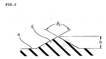
- the shape of the first helical ribs can be, for example, a mountainous or a bilge or a triangular shape in cross section of A-A line in FIG.1, however triangular shape which is shown in FIG.2, is preferable.
- the top opening angle ⁇ 2 of the substantially triangular shaped ribs 6, as shown in FIG.2, is in the range of about 90° to 150° , preferably in the range of 100° to 140° .
- the first helical ribs have a predetermined controlled height throughout the length, as measured from the third flat surface 4, and the range of the height h, which is shown in FIG.2, is about 0.005 mm to 0.1 mm, preferably 0.005 mm to 0.08 mm.
- the height of the ribs h is not more than 0.005 mm, pumping function to pump oil back to the oil-side A is small.
- the height of the ribs h is not less than 0.1 mm, there is often some oil leakage through the portion between the third flat surface 4 and the shaft 21 at the time the shaft is not driving, or at the time the shaft is rotating in reverse revolution.
- the pitch p is a predetermined distance of the helical ribs relative to each other as shown in FIG.1.
- One of the examples of the first helical ribs of the first embodiment of the present invention is as follows;
- Seal lip of the present invention is usually made of elastic compounds including rubber like materials and fillers.
- the third flat surface 4 sealingly contacts, with predetermined width W in the direction of the axis of the shaft 21, with the outer surface of the shaft 21.
- relatively large contact area with the shaft 21 can be attained by the existence of the flat surface 4, bringing contact pressure per unit area of the third flat surface into relatively low.
- This contact condition is just like one that can be attained after the conventional seal lip without the third flat surface is used on and abraded by the shaft 21, after a sufficient operating time, to give a fully (saturatedly) abraded seal lip.
- the first pumping helical ribs 6, which have a property to pump oil back to the oil-side A are provided on the third flat surface 4 having an excellent anti-abrasion property due to its configuration mentioned above, the first helical ribs are also difficult to be abraded, thereby pumping function by the first helical ribs can be maintained for a long period of time in use.
- first helical ribs 6 can be placed in a reverse direction with an angle (namely 180- ⁇ 1) to the edge line 4a. If some of the first helical ribs 6 is placed in a reverse direction relative to the rest of the first helical ribs, pumping function can be effectively secured even when the shaft 21 rotates in reverse direction.
- each of all these first helical ribs does not cross over relative to each other.
- FIG.3, 4, 5A and 5B show second embodiment of the present invention. Same reference numerals are used as in FIG.1 and in FIG.2, except some reference numerals.
- a frustoconical oil-side surface 2 inner diameter of which gradually increases toward oil-side A
- a frustoconical air-side surface 3 inner diameter of which gradually increases toward air-side B
- a third substantially frustoconical (or flat) surface 4 having a predetermined width W in the direction of the axis of the oil seal in actual size.
- the third flat surface 4 sealingly engages with the shaft 21 in use.
- the flat surface 4 is shown, as is mentioned above in the first embodiment, like a frustoconical surface having a diameter thereof gradually increasing from the oil-side A to the air-side B .
- This configuration depends on the fact that the oil seal is not fitted on the member (shaft) 21, so the seal lip 1 is in a free state.
- the seal lip 1 is moved toward C axis around a support portion 5, which is supported by a rigid annular casing (not shown), by the interference between the shaft 21 and the seal lip 1 in FIG.3, thereby resulting a fully contact of the whole flat surface 4 with the shaft 21 to bring the frustoconical shape of the flat surface 4 into a cylindrical (or flat) shape.
- each preferable angle of ⁇ , ⁇ and ⁇ which are shown in FIG.3, is as follows as is mentioned in the first embodiment.
- a preferable angle ⁇ between the central axis of the oil seal and the frustoconical oil-side surface 2 was in the range of about 40° to 60°
- a preferable angle ⁇ between the central axis of the oil seal and the frustoconical air-side surface 3 was in the range of about 15° to 30°
- a preferable angle ⁇ between the central axis of the oil seal and the third flat surface 4 was in the range of about 5° to 15° , as is shown in FIG.3.
- the width W of the third flat surface 4 in the direction of the central axis of the oil seal was preferably about 0.1 mm to 1.5 mm in actual size.
- a width of the third flat surface may be made wider with increasing an inside diameter of a seal lip 1 of an oil seal.
- first helical ribs 6 to pump oil back (or fluid, not shown) to the oil-side A are formed, integrally with and on the third flat surface 4, in a parallel manner relative to each other, and placed at about even intervals relative to each other on around the third flat surface, as shown in FIG.3.
- One end portion 6a of the first helical ribs 6 start at around the edge line 4a and extend toward the edge line 4b aslant the third flat surface to reach to the other end portion 6b at around the edge line 4b. It is more desirable, for securing better pumping function of the helical ribs, that each end portions 6a and 6b is on the edge line 4a or 4b respectively.
- the angle ⁇ 1 between the edge 4a and the ribs, as shown in FIG.3, is in the range of about 10° to 45° , preferably of about 15° to 40° . In the case the angle is not more than about 10° , there is often some oil (or fluid) leakage from the oil-side A to the air-side B through the portion between the shaft 21 and the third flat surface 4 at the time of reverse revolution of the shaft 21.
- first helical ribs 6 can be placed in a reverse direction with an angle (namely 180- ⁇ 1) to the edge line 4a. If some of the first helical ribs 6 is placed in a reverse direction relative to the rest of the first helical ribs, pumping function can be effectively secured even when the shaft 21 rotates in reverse direction.
- each of all these first helical ribs does not cross over relative to each other.
- the shape of the first helical ribs can be, for example, a mountainous or a bilge or a triangular shape in cross section of B-B line in FIG.3, however triangular shape which is shown in FIG. 4, is preferable.
- the top opening angle ⁇ 2 of the substantially triangular shaped ribs 6, as shown in FIG.4, is in the range of about 90° to 150° , preferably in the range of 100° to 140° .
- the first helical ribs have a predetermined controlled height throughout its length, as measured from the third flat surface 4, and the range of the height h, which is shown in FIG.2, is about 0.005 mm to 0.1 mm, preferably 0.005 mm to 0.08 mm.
- the height of the ribs h is not more than 0.005 mm, pumping function to pump back oil to the oil-side A is small.
- the height of the ribs h is not less than 0.1 mm, there is often some oil leakage through the portion between the third flat surface 4 and the shaft 21 at the time the shaft is not driving, or at the time the shaft is rotating in reverse revolution.
- the pitch p is a predetermined distance of the helical ribs relative to each other as shown in FIG.3.
- One of the example of the first helical ribs of the second embodiment of the present invention is as follows;
- mountainous or bilge or triangular C-C line cross sectional shaped helical pumping ribs 10 having a pumping function to pump oil (or fluid, not shown) back to the oil-side A are provided, integrally with the frustoconical air-side surface, in a parallel manner relative to each other, and placed at about even intervals relative to each other on and around the frustoconical air-side surface 3, as shown in FIG.3.
- This second helical pumping ribs provide, also, the seal lip 1 with a further pumping function to pump oil back to the oil-side A , similar to the first helical pumping ribs 6 on the third flat surface 4.
- the second helical pumping ribs provide the seal lip 1 with a pumping function even after the first helical pumping ribs disappeared, in the case of heavy abrasion by the shaft 21, from the third flat surface 4, giving the seal lip 1 a more stable pumping function for a long time as well as its initial stage in use.
- Each one end portion 10a of the second helical ribs 10 starts at and integrally connects with the end portion 6b of the first helical ribs 6, near the third flat surface 4 as shown in FIG.3 and FIG.5B; and extends toward the air-side B , with gradually increasing in height and width at least at an initial portion near the edge line 4b.
- the good pumping function to pump oil back to the oil-side A can not be sometimes obtained.
- the end portion 10b of the second helical ribs 10 is located within, and at near the edge of the air-side of, the frustoconical air-side surface 3, as shown in FIG.3.
- the second helical ribs are also placed aslant the width W2 of the frustoconical air-side surface 3.
- the angle ⁇ 3 between the edge line 4b and the central line of the long direction of the second helical ribs 10, as shown in FIG.3, is in the range of about 10° to 45° , preferably of about 15° to 40° .
- the angle ⁇ 3 is not more than about 10° , there often shows a small additional pumping function other than the pumping function by the first helical ribs 6 , at the early stage in use as well as after the long period in use.
- the angle ⁇ 3 is not less than about 45° , the additional pumping function other than the pumping function by the first helical ribs 6 often becomes small.
- the second helical ribs 10 are placed in a reverse direction with an angle (namely 180- ⁇ 3) to the edge line 4b, when the first helical ribs 6 are placed in a reverse direction with an angle (namely 180- ⁇ 1) to the edge line 4a.
- the second helical ribs can take various size and shape as long as the pumping function is secured.
- the shape of the second helical ribs is preferably, for example, a mountainous or a bilge or a triangular shape in cross section of C-C line in FIG.3. Triangular type in cross section of C-C line in FIG.3 is more preferable because of a mold for this type of oil seal being easy to make.
- the cross sectional shape in cross section of D-D line in FIG.3 is also a mountainous or a bilge, or a straight type.
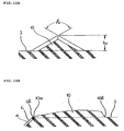
- FIG.5A shows, for example, a triangular in shape in cross section of C-C line in FIG.3.
- FIG.5B shows, for example, a bilge type in cross section of D-D line in FIG.3.
- FIG.12, 13 show each perspective view of the bilge type or the mountainous type (FIG.12), and straight type (FIG.13) respectively.
- FIG.14 shows one of a variation of mountainous or bilge type second helical pumping ribs having about somewhat symmetrical shape in long direction.
- the top opening angle ⁇ 4 of the second helical ribs 10, as shown in FIG.5A, is in the range of about 90° to 150° , through almost its entire length of the ribs, preferably in the range of 100° to 140° .
- the top opening angle ⁇ 4 of the ribs, which are shown in FIG. 12, 13 and 14, are also in the same range as mentioned above.
- the second helical ribs have a predetermined controlled height h2 at the highest point thereof, as shown in FIG. 5A, as measured from the frustoconical air-side surface 3; and the range of the height h2 is about 0.005 mm to 2 mm or more, preferably 0.1 mm to 2 mm.
- the height of the second ribs is not more than 0.005 mm, pumping function to pump oil back to the oil-side A is small.
- the height h2 can be increased until the top of the ribs reaches the shaft 21 when the oil seal is fitted on the shaft 21.
- the shape of the second helical ribs 10 in FIG. 3 is a mountainous or bilge type, and the width and the height of the ribs gradually increase from the oil-side A to the air-side B until the highest portion of h2, and thereafter somewhat rapidly decrease to become zero at the outermost point 10b.
- the number of ribs 10 is the same of the first helical ribs 6, and placed approximately same direction of the first helical ribs as shown in FIG.3.
- the number of the second helical ribs 10, however, can be any number, as long as the pumping function is secured.
- One of the example of the second helical ribs of the second embodiment of the present invention is as follows;
- a groove 7 is formed to accommodate a conventional garter spring 8, which gives a predetermined interference to the seal lip 1 when the seal lip is mounted on the shaft 21.
- a conventional dust lip 9 is also a conventional dust lip 9 at the inner peripheral portion of the base portion 6.
- Seal lip is usually made of elastic composite materials such a compound as rubber like materials containing fillers.
- the third flat surface 4 sealinly thankacts, with predetermined width W in the direction of the axis of the shaft 21, with the outer surface of the shaft 21.
- relatively large contact area with the shaft 21 can be attained by the existence of the flat surface 4, bringing contact pressure per unit area of the third flat surface into relatively low.
- This contact condition is just like one that can be attained after the conventional seal lip without the third flat surface is used on and abraded by the shaft 21, for a sufficient long operating time, to give a fully (saturatedly) abraded seal lip.
- further abrasion of the third flat surface by the shaft 21 is not likely to be occurred easily, and a stable and snug contact condition between the flat surface and the shaft 21 can be attained, resulting in good sealing condition.
- the second helical ribs 10 are provided on the frustoconical air-side surface, even in the case after the first helical ribs are consumed by abrasion between the third flat surface 4 and the shaft 21, pumping function by the second helical ribs on the frustoconical surface is remained, resulting in providing the oil seals with more excellent sealing properties for a long period of time as well as its initial stage in use.
- FIG.6, FIG.7, FIG.8A and FIG.8B show third embodiment of the present invention. Same reference numerals are used as in FIG.3 to FIG.5B except some reference numerals.
- the third embodiment is similar to the second embodiment except the location of the second helical pumping ribs. Namely, the first helical pumping ribs 6 are the same as in FIG.6 of the second embodiment in the shape and the dimension as well as in the number of the ribs, as shown in FIG.6 and FIG 7. And the angle ⁇ , ⁇ and ⁇ are similar to that of the first and second embodiment.
- first helical ribs 6 can be placed in a reverse direction with an angle (namely 180- ⁇ 1) to the edge line 4a. If some of the first helical ribs 6 is placed in a reverse direction relative to the rest of the first helical ribs, pumping function can be effectively secured even when the shaft 21 rotates in reverse direction.
- each of all these first helical ribs does not cross over relative to each other.
- the second helical pumping ribs are placed in a manner that one end portions of the ribs 10a on the edge line 4b are not integrally connected to the end portions 6b of the first helical ribs, in other words, the end portion 10a of the second helical ribs 10 are placed between the end portions 6b and 6b of the first helical ribs 6 and 6 as shown in FIG.6.
- the edge portions 10a of the second helical ribs 10 start at around the edge line 4b, and the cross sectional shape of the line F-F is a triangular type similar to that of the second embodiment as shown in FIG.8A.
- the top opening angle ⁇ 4 and the maximum height are also similar to that of FIG.5A of the second embodiment.
- the cross sectional shape of the line G-G is a helical one as is shown in FIG.8B.
- the outermost tip portion 10a of the second ribs 10 are preferably integrally formed on the third flat surface to fully secure, even at the initial stage in use, the pumping function of the second ribs on the frustoconical air-side surface. But if the outermost tip in the end portion 10a can be accurately made on the edge line 4b, the pumping function may be also secured. At this latter case, however, the working to make a mold (not shown) for oil seals becomes somewhat meticulous.
- the shape of the second helical ribs 10 of the third embodiment can be similar to the second embodiment, as shown in FIG.12, FIG.13 and FIG.14 except the shape of the tip 10a of the ribs 10.
- first helical pumping ribs 6 on the third flat surface 4 and the second helical pumping ribs 10 on the frustoconical air-side surface 3 are placed in a manner that all of each two ribs 6, 10 are not exactly continuously connected each other at their end portions 6b, 10a, therefore processability for making a mold (not shown) of this type of seal lip 1 is better than that of the Second embodiment.
- FIG.9, 10, 11A and 11B show fourth embodiment of the present invention. Same reference numerals are used as in FIG.6, 7, 8A and 8B except some reference numerals.
- a frustoconical oil-side surface 2 inner diameter of which gradually increasing toward oil-side A
- a frustoconical air-side surface 3 inner diameter of which gradually increasing toward air-side B
- a third substantially frustoconical (or flat) surface 4 having a predetermined width W in actual size as shown in FIG.9. The third flat surface sealingly engages with the shaft 21 in use.
- the flat surface 4 is shown, as is mentioned above in the first embodiment, like a frustoconical surface having a diameter thereof gradually increasing from the oil-side A to the air-side B .
- This configuration depends on the fact that the oil seal is not fitted on the member (shaft) 21, so the seal lip 1 is in a free state.
- the seal lip 1 is moved toward C axis around a support portion 5, which is supported by a rigid annular casing (not shown), by the interference between the shaft 21 and the seal lip 1 in FIG.9, thereby resulting a fully contact of the whole flat surface 4 with the shaft 21 to bring the frustoconical shape of the flat surface 4 into a cylindrical shape.
- each preferable angle of ⁇ , ⁇ and ⁇ which are shown in FIG.9, is as follows as is mentioned in the first embodiment.
- a preferable angle ⁇ between the central axis of the oil seal and the frustoconical oil-side surface 2 was in the range of about 40° to 60°
- a preferable angle ⁇ between the central axis of the oil seal and the frustoconical air-side surface 3 was in the range of about 15° to 30°
- a preferable angle ⁇ between the central axis of the oil seal and the third flat surface 4 was in the range of about 5° to 15° , as is shown in FIG.3.
- the width W of the third flat surface 4 in the direction of the central axis of the oil seal was preferably about 0.1 mm to 1.5 mm in actual size.
- a width of the third flat surface may be made wider with increasing an inside diameter of a seal lip 1 of an oil seal.
- first helical ribs 6 and 6' to pump oil (or fluid, not shown) back to the oil-side A are formed, integrally with and on the third flat surface 4.
- each first rib or a group of a plurality of the first rib are placed alternately and evenly in a manner that the slope of a rib or a group of a plurality of rib is reverse relative to each other or relative to each group of a plurality of the rib (in FIG.9, each first rib is placed alternately in reverse manner). All of each rib or each group of a plurarilty of the rib are preferably placed at approximately even intervals on around the third flat surface.
- One end portion 6a or 6'a of the first helical ribs 6 or 6' start at around the edge line 4a and extend toward the edge line 4b aslant the third flat surface to reach to the other end portion 6b at around the edge line 4b. It is more desirable, for securing better pumping function of the helical ribs, that each end portions 6a or 6'a and 6b or 6'b is on the edge line 4a or 4b respectively.
- pumping function to pump oil back to the oil-side A can not be fully secured.
- the angle ⁇ 1 and ⁇ 1 between the edge 4a and the ribs 6 and 6', as shown in FIG.9, is in the range of about 10° to 45° , preferably of about 15° to 40° . In the case the angle is not more than about 10° , there is often some oil (or fluid) leakage from the oil-side A to the air-side B through the portion between the shaft 21 and the third flat surface 4 at the time of reverse revolution of the shaft 21.
- the shape of the first helical ribs can be, for example, a mountainous or a bilge or a triangular shape in cross section of H-H line of FIG.9, triangular shape which is shown in FIG. 4, is, however, preferable throughout its entire length.
- the shape of the ribs 6' is also the same shape as that of the ribs 6.
- the top opening angle ⁇ 2 of the substantially triangular shaped ribs 6 and 6', as shown in FIG.10, is in the range of about 90° to 150° , preferably in the range of 100° to 140° .
- the first helical ribs 6 and 6' have a predetermined controlled height throughout the length thereof, as measured from the third flat surface 4, and the range of the height h, which is shown in FIG.10, is about 0.005 mm to 0.1 mm, preferably 0.005 mm to 0.08 mm.
- the height of the ribs h is not more than 0.005 mm, pumping function to pump oil back to the oil-side A is small.
- the height of the ribs h is not less than 0.1 mm, there is often some oil leakage through the portion between the third flat surface 4 and the shaft 21 at the time that there is no relative movement between the seal lip and the shaft 21, or at the time the shaft is rotating in reverse direction.
- One of the example of the first helical ribs of the fourth embodiment of the present invention is as follows;
- unit represents a pair of a rib or a pair of a group of a plurality of rib, consisting of a rib or ribs 6 having a slope in a normal direction, and of a rib or ribs 6' having a slope in a reverse direction as is shown in FIG.9.
- Each rib in each group of a plurality of rib of the unit is placed in an approximately same direction and placed in a parallel manner relative to each other.
- This first helical pumping ribs 6' on the third flat surface 4 also, have a pumping function to pump oil back to the oil-side A at the time when the shaft 21 is rotating in reverse direction.
- this type of oil seal has a property that, even when the shaft drives in a reverse revolution these ribs pump oil back to the oil-side as well as the time the shaft drives in a normal revolution.
- mountainous or bilge or triangular shape helical ribs 10 having a pumping function to pump oil (or fluid, not shown) back to the oil-side A are further provided, integrally on the frustoconical air-side surface, in a parallel manner relative to each other, and placed at approximately even intervals relative to each other on and around the frustoconical air-side surface 3, as shown in FIG.9.
- This second helical pumping ribs provide, also, the seal lip 1 with a further pumping function to pump oil back to the oil-side A , similar to the first helical pumping ribs 6 on the third flat surface 4.
- the second helical pumping ribs provide the seal lip 1 with a pumping function even after the first helical pumping ribs disappeared, in the case of heavy abrasion by the shaft 21, from the third flat surface 4, giving the seal lip 1 a stable pumping function for a long time as well as its initial stage in use.
- the second helical pumping ribs are placed on the frustoconical air-side surface in a manner that one end portions 10a of the ribs 10 on around the edge line 4b are not necessarily integrally connected to the end portions 6b or 6'b of the first helical ribs 6 pr 6', in other words, the end portion 10a of the second helical ribs 10 can be placed at the place between the end portions 6b, 6b, 6'b and 6'b of the first helical ribs 6 or 6'.
- the edge portions 10a of the second helical ribs 10 start at around the edge line 4b and extends toward the air-side B , with gradually increasing in height and width at least at an initial portion near the edge line 4b.
- the good pumping function to pump oil back to the oil-side A can not be sometimes secured.
- the end portion of the second helical ribs 10 is located within, and at near the edge of the air-side of, the frustoconical air-side surface 3, as shown in FIG.9.
- the second helical ribs are placed aslant the width W2 of the frustoconical air-side surface 3.
- the angle ⁇ 3 between the edge line 4b and the central line of the long direction of the second helical ribs, as shown in FIG.9, is in the range of about 10° to 45° , preferably of about 15° to 40° .
- the angle ⁇ 3 is not more than about 10° , there often shows a small additional pumping function other than the pumping function by the first helical ribs 6, 6' , at the early stage in use as well as after the long period in use.
- the angle ⁇ 3 is not less than about 45° , the additional pumping function other than the pumping function by the first helical ribs 6 or 6' often becomes small.
- the second helical pumping ribs can be placed in a reverse direction as long as the range of the angle ⁇ 3 is within 10° to 45° (namely 180- ⁇ 3), as mentioned above.
- the second helical ribs can take various size and shape as long as the pumping function is secured.
- the shape of the second helical ribs is, for example, a mountainous or a bilge or a triangular shape in cross section of I-I line in FIG.9.
- Triangular cross sectional shape in I-I line in FIG.9 is preferable because of a mold (not shown) having this shape of oil seal being easy to make.
- the cross sectional shape in cross section of J-J line in FIG.9 is also a mountainous or a bilge, or a straight type.
- FIG.11A shows, for example, a triangular in shape in cross section of I-I line in FIG.9.
- FIG.11B shows, for example, a bilge type in cross section of J-J line in FIG.9.
- FIG.12, 13 show each perspective view of the bilge type or the mountainous type (FIG.12), and straight type (FIG.13) respectively.
- FIG.14 shows one of a variation of mountainous or bilge type second helical pumping ribs having about somewhat symmetrical shape in long direction.
- the outermost tips of the portion 10a of the ribs 10 can be connected to the end portion 6b or 6'b of the first ribs 6 or 6' (as shown in FIG.12, 13 and 14) or can be placed on the third flat surface as is shown in FIG.11B.
- the top opening angle ⁇ 4 of the second helical ribs 10, as shown in FIG.11A, is in the range of about 90° to 150° , through almost its entire length of the ribs, preferably in the range of 100° to 140° .
- the top opening angle ⁇ 4 of the ribs, which are shown in FIG. 12, 13 and 14, are also in the same range as mentioned above.
- the second helical ribs 10 have a predetermined controlled height h2 at the highest point thereof, as shown in FIG. 11A, as measured from the frustoconical air-side surface 3; and the range of the height h2 is about 0.005 mm to 2 mm or more, preferably 0.1 mm to 2 mm.
- the height of the second ribs is not more than 0.005 mm, pumping function to pump oil back to the oil-side A is small.
- the height h2 can be increased until the top of the ribs reaches the shaft 21 when the oil seal is fitted on the shaft 21.
- the shape of the second helical ribs 10 in FIG.9 is a mountainous or bilge type, and the width and the height of the ribs gradually increase from the oil-side A to the air-side B until the highest portion of h2, and thereafter somewhat rapidly decrease to become zero at the outermost point 10b.
- the number of ribs 10 can be taken any number. These ribs are usually placed evenly on the frustoconical air-side surface.
- One of the example of the second helical ribs of the fourth embodiment of the present invention is as follows;
- a groove 7 is formed to accommodate a conventional garter spring 8, which gives a predetermined interference to the seal lip 1 when the seal lip is mounted on the shaft.
- a conventional dust lip 9 is also a conventional dust lip 9 at the inner peripheral portion of the base portion 6.
- Seal lip is usually made of elastic composite materials such as a compound comprising rubber like material and filler.
- the third flat surface 4 sealinly, with predetermined width W in the direction of the axis of the shaft 21, contacts with the outer surface of the shaft 21.
- relatively large contact area with the shaft 21 can be attained by the existence of the flat surface 4, bringing contact pressure per unit area of the third flat surface into relatively low.
- This contact condition is just like one that can be attained after the conventional seal lip without the third flat surface is used on and abraded by the shaft 21, for a sufficient operating time, to give a fully (saturatedly) abraded seal lip.
- further abrasion of the third flat surface by the shaft 21 is not likely to be occurred easily, and a stable and snug contact condition between the flat surface and the shaft 21 can be attained, resulting in a good sealing condition.
- the first pumping helical ribs 6, 6' which have a property to pump oil back to oil-side A, are provided on the third flat surface 4 having an excellent anti-abrasion property in its configuration mentioned above, the first helical ribs are also difficult to be abraded, thereby pumping function by the first helical ribs can be maintained for a long time in use. From above mentioned reasons, preventing pumping property of the third helical ribs from being deteriorated for a relatively short period in use can be achieved, thereby excellent sealing property of this type of oil seals can be maintained for a long period of time as well as at its initial stage in use.
- the second helical ribs 10 are provided on the frustoconical air-side surface, even in the case after the first helical ribs is consumed by abrasion which is occurred at the portion between the third flat surface 4 and the shaft 21, pumping function by the second helical ribs on the frustoconical air-side surface is remained, thereby resulting in providing oil seals with more excellent sealing properties for a long period of time as well as its initial stage in use.
- first helical pumping ribs 6 on the third flat surface 4 and the second helical pumping ribs 10 on the frustoconical air-side surface 3 are placed in a manner that all of each two ribs 6, 10 are not exactly continuously connected each other, therefore processability for making a mold (not shown) of this type of seal lip 1 can be comparatively improved.
- first helical pumping ribs 6' on the third flat surface 4 are placed in a reverse direction with respect to the angle between the edge line 4a and the first helical pumping ribs 6, pumping function can be secured even when the shaft 21 rotates in a reverse direction.
- the shapes of the second helical pumping ribs 10 mentioned above are only preferable several examples of the present invention and are therefore not limited to these embodiments.
- the cross sectional shape of the second helical ribs can be any type, and the height and the width of the second helical pumping ribs 10 can be formed somewhat uniformly through their entire length as long as the pumping function is secured.
- the oil seals of the present invention provide an excellent anti-wearability and an excellent stability in sealing functions in a long period of time as well as in its initial stage in use, due to the existence of, on an inner periphery of a seal lip, a so-called third flat surface 4 similar to just like one (like a fully saturatedly abraded seal lip) that is obtained after a conventional seal lip without the so-called flat surface is used on and abraded by a shaft 21, for a sufficient operating time.
- a larger contact area with the shaft 21 are there in this so-called third flat surface 4, due to the existence of the so-called third flat surface 4, resulting in sufficiently low contact pressure thereof per unit area of the so-called third flat surface.
- first pumping helical ribs which have a property to pump oil back to an oil-side A, are provided on the so-called third flat surface having an excellent anti-abrasion property due to its configuration mentioned above, the first helical ribs are also difficult to be abraded, thereby pumping function by the first pumping helical ribs on the so-called third flat surface can be maintained for a long time in use.
- the first pumping helical ribs are so designed to be deformed due to their configuration when the oil seal is fitted on the shaft 21, that the so-called third flat surface with the first pumping helical ribs is brought into a snuglly engaging condition with the shaft 21, resulting in preventing oil leakage from the oil-side to an air-side through the contact portion between the so-called third flat surface and the shaft 21 even at the time the shaft 21 is not rotating.
- first helical ribs 6 are provided on the so-called third flat surface 4, but also a second helical ribs 10 are provided on the frustoconical air-side surface, even in the case after the first helical ribs 6 is consumed by abrasion which is occurred at the portion between the so-called thied flat surface 4 and the shaft 21, pumping function by the second helical ribs on the frustoconical air-side surface is remained, thereby resulting in providing oil seals with more excellent sealing properties for a long period of time as well as its initial stage in use.
Landscapes
- Engineering & Computer Science (AREA)
- General Engineering & Computer Science (AREA)
- Physics & Mathematics (AREA)
- Fluid Mechanics (AREA)
- Mechanical Engineering (AREA)
- Sealing With Elastic Sealing Lips (AREA)
Applications Claiming Priority (2)
| Application Number | Priority Date | Filing Date | Title |
|---|---|---|---|
| JP6197498 | 1998-02-27 | ||
| JP6197498 | 1998-02-27 |
Publications (2)
| Publication Number | Publication Date |
|---|---|
| EP0939257A2 true EP0939257A2 (de) | 1999-09-01 |
| EP0939257A3 EP0939257A3 (de) | 2000-05-31 |
Family
ID=13186669
Family Applications (1)
| Application Number | Title | Priority Date | Filing Date |
|---|---|---|---|
| EP99103640A Withdrawn EP0939257A3 (de) | 1998-02-27 | 1999-02-25 | Radialwellendichtung |
Country Status (2)
| Country | Link |
|---|---|
| US (1) | US6276691B1 (de) |
| EP (1) | EP0939257A3 (de) |
Cited By (3)
| Publication number | Priority date | Publication date | Assignee | Title |
|---|---|---|---|---|
| US7645412B2 (en) | 2002-02-28 | 2010-01-12 | Nok Corporation | Sealing device |
| US8413995B2 (en) | 2007-04-11 | 2013-04-09 | Nok Corporation | Oil seal |
| CN104254720A (zh) * | 2012-04-27 | 2014-12-31 | Nok株式会社 | 密封装置 |
Families Citing this family (14)
| Publication number | Priority date | Publication date | Assignee | Title |
|---|---|---|---|---|
| AU2003261994A1 (en) * | 2002-09-09 | 2004-03-29 | Nok Corporation | Sealing device |
| JP2005172061A (ja) * | 2003-12-09 | 2005-06-30 | Nok Corp | 密封装置 |
| TWI275723B (en) * | 2005-12-29 | 2007-03-11 | Nak Sealing Technologies Corp | Sealing component |
| CN101802466B (zh) * | 2007-09-04 | 2013-06-12 | 株式会社荒井制作所 | 密封装置 |
| JP2009074602A (ja) * | 2007-09-20 | 2009-04-09 | Nok Corp | オイルシール |
| WO2012152808A1 (en) | 2011-05-12 | 2012-11-15 | Aktiebolaget Skf | Texturized seal |
| US9309615B2 (en) * | 2012-06-26 | 2016-04-12 | BSH Hausgeräte GmbH | Water-conducting household appliance having a rotatable component |
| DE102013207029B4 (de) * | 2013-04-18 | 2016-05-04 | Aktiebolaget Skf | Radialwellen-Dichtungsanordnung |
| JP6177582B2 (ja) * | 2013-05-14 | 2017-08-09 | Nok株式会社 | 密封装置 |
| JP6231352B2 (ja) * | 2013-10-29 | 2017-11-15 | Nok株式会社 | オイルシール |
| WO2016158211A1 (ja) * | 2015-03-31 | 2016-10-06 | Nok株式会社 | 密封装置 |
| JP6809847B2 (ja) * | 2016-09-01 | 2021-01-06 | Nok株式会社 | 密封装置 |
| DE102019002953A1 (de) * | 2019-04-18 | 2020-10-22 | Kaco Gmbh + Co. Kg | Radialwellendichtung |
| JP2025118459A (ja) * | 2024-01-31 | 2025-08-13 | Nok株式会社 | 密封装置 |
Citations (1)
| Publication number | Priority date | Publication date | Assignee | Title |
|---|---|---|---|---|
| JPH07301339A (ja) | 1994-03-11 | 1995-11-14 | Nok Corp | オイルシール |
Family Cites Families (7)
| Publication number | Priority date | Publication date | Assignee | Title |
|---|---|---|---|---|
| US3930655A (en) * | 1968-01-24 | 1976-01-06 | Dowty Seals Limited | Seals for use between two relatively-rotating surfaces |
| DD107968A1 (de) * | 1972-05-23 | 1974-08-20 | ||
| GB2032538B (en) * | 1978-10-20 | 1982-09-08 | Freudenberg C | Radical shaft sealing rings |
| FR2456888A1 (fr) * | 1979-05-14 | 1980-12-12 | Procal | Dispositif d'etancheite a effet hydrodynamique |
| US4288083A (en) * | 1980-02-07 | 1981-09-08 | International Packings Corporation | Hydrodynamic shaft seal |
| DE3833042A1 (de) * | 1988-09-29 | 1990-04-12 | Freudenberg Carl Fa | Wellendichtung |
| US5759466A (en) | 1995-05-25 | 1998-06-02 | Nok Corporation | Method of making lip-type oil seals having improved sealing edge |
-
1999
- 1999-02-25 EP EP99103640A patent/EP0939257A3/de not_active Withdrawn
- 1999-03-01 US US09/259,257 patent/US6276691B1/en not_active Expired - Lifetime
Patent Citations (1)
| Publication number | Priority date | Publication date | Assignee | Title |
|---|---|---|---|---|
| JPH07301339A (ja) | 1994-03-11 | 1995-11-14 | Nok Corp | オイルシール |
Cited By (9)
| Publication number | Priority date | Publication date | Assignee | Title |
|---|---|---|---|---|
| US7645412B2 (en) | 2002-02-28 | 2010-01-12 | Nok Corporation | Sealing device |
| US8413995B2 (en) | 2007-04-11 | 2013-04-09 | Nok Corporation | Oil seal |
| EP2151612A4 (de) * | 2007-04-11 | 2014-08-20 | Nok Corp | Öldichtung |
| CN104254720A (zh) * | 2012-04-27 | 2014-12-31 | Nok株式会社 | 密封装置 |
| EP2843269A4 (de) * | 2012-04-27 | 2015-08-05 | Nok Corp | Dichtungsvorrichtung |
| CN105587864A (zh) * | 2012-04-27 | 2016-05-18 | Nok株式会社 | 密封装置 |
| CN104254720B (zh) * | 2012-04-27 | 2016-08-17 | Nok株式会社 | 密封装置 |
| US9593776B2 (en) | 2012-04-27 | 2017-03-14 | Nok Corporation | Sealing device |
| US9644743B2 (en) | 2012-04-27 | 2017-05-09 | Nok Corporation | Sealing device |
Also Published As
| Publication number | Publication date |
|---|---|
| EP0939257A3 (de) | 2000-05-31 |
| US6276691B1 (en) | 2001-08-21 |
Similar Documents
| Publication | Publication Date | Title |
|---|---|---|
| US6276691B1 (en) | Oil seal | |
| US6726211B1 (en) | Sealing device | |
| US5860656A (en) | Seal for rotating shaft | |
| JP3278349B2 (ja) | 密封装置 | |
| US6860486B2 (en) | Shaft sealing ring | |
| EP2151612B1 (de) | Öldichtung | |
| KR100417478B1 (ko) | 회전 샤프트 시일 | |
| CN100436896C (zh) | 密封装置 | |
| JP6961094B2 (ja) | 密封装置 | |
| JPH0243940B2 (de) | ||
| US6705617B2 (en) | Hydrodynamic seal and method of making the same | |
| JP4855936B2 (ja) | シール装置 | |
| US20050242521A1 (en) | Radial shaft sealing ring | |
| KR20040103402A (ko) | 회전축 실 | |
| JP3180285B2 (ja) | オイルシール | |
| JP7644771B2 (ja) | 密封装置 | |
| JP4600633B2 (ja) | オイルシール | |
| JP3068170B2 (ja) | オイルシール | |
| JP3811595B2 (ja) | オイルシール | |
| JPH0656568U (ja) | オイルシ−ル | |
| JP2883551B2 (ja) | ねじ付オイルシール | |
| JP2001173798A (ja) | ねじ付オイルシール | |
| JP4515048B2 (ja) | 回転軸シール | |
| JP2002206644A (ja) | 密封装置 | |
| JP3821931B2 (ja) | 密封装置 |
Legal Events
| Date | Code | Title | Description |
|---|---|---|---|
| PUAI | Public reference made under article 153(3) epc to a published international application that has entered the european phase |
Free format text: ORIGINAL CODE: 0009012 |
|
| AK | Designated contracting states |
Kind code of ref document: A2 Designated state(s): AT DE ES FR GB IT SE |
|
| AX | Request for extension of the european patent |
Free format text: AL;LT;LV;MK;RO;SI |
|
| PUAL | Search report despatched |
Free format text: ORIGINAL CODE: 0009013 |
|
| AK | Designated contracting states |
Kind code of ref document: A3 Designated state(s): AT BE CH CY DE DK ES FI FR GB GR IE IT LI LU MC NL PT SE |
|
| AX | Request for extension of the european patent |
Free format text: AL;LT;LV;MK;RO;SI |
|
| 17P | Request for examination filed |
Effective date: 20000429 |
|
| AKX | Designation fees paid |
Free format text: AT DE ES FR GB IT SE |
|
| STAA | Information on the status of an ep patent application or granted ep patent |
Free format text: STATUS: THE APPLICATION IS DEEMED TO BE WITHDRAWN |
|
| 18D | Application deemed to be withdrawn |
Effective date: 20010901 |