EP0939460A2 - Structure de connexion pour douille d'ampoule et un fil électrique - Google Patents
Structure de connexion pour douille d'ampoule et un fil électrique Download PDFInfo
- Publication number
- EP0939460A2 EP0939460A2 EP99300492A EP99300492A EP0939460A2 EP 0939460 A2 EP0939460 A2 EP 0939460A2 EP 99300492 A EP99300492 A EP 99300492A EP 99300492 A EP99300492 A EP 99300492A EP 0939460 A2 EP0939460 A2 EP 0939460A2
- Authority
- EP
- European Patent Office
- Prior art keywords
- core wire
- bulb socket
- wire
- members
- electric wire
- Prior art date
- Legal status (The legal status is an assumption and is not a legal conclusion. Google has not performed a legal analysis and makes no representation as to the accuracy of the status listed.)
- Withdrawn
Links
- 238000009413 insulation Methods 0.000 claims description 3
- 230000003247 decreasing effect Effects 0.000 abstract description 2
- 230000001105 regulatory effect Effects 0.000 description 5
- 238000011084 recovery Methods 0.000 description 4
- 239000002184 metal Substances 0.000 description 3
- 238000003780 insertion Methods 0.000 description 1
- 230000037431 insertion Effects 0.000 description 1
- 239000000463 material Substances 0.000 description 1
- 238000000034 method Methods 0.000 description 1
- 230000000717 retained effect Effects 0.000 description 1
- 238000003466 welding Methods 0.000 description 1
Images


Classifications
-
- H—ELECTRICITY
- H01—ELECTRIC ELEMENTS
- H01R—ELECTRICALLY-CONDUCTIVE CONNECTIONS; STRUCTURAL ASSOCIATIONS OF A PLURALITY OF MUTUALLY-INSULATED ELECTRICAL CONNECTING ELEMENTS; COUPLING DEVICES; CURRENT COLLECTORS
- H01R33/00—Coupling devices specially adapted for supporting apparatus and having one part acting as a holder providing support and electrical connection via a counterpart which is structurally associated with the apparatus, e.g. lamp holders; Separate parts thereof
- H01R33/05—Two-pole devices
- H01R33/06—Two-pole devices with two current-carrying pins, blades or analogous contacts, having their axes parallel to each other
- H01R33/09—Two-pole devices with two current-carrying pins, blades or analogous contacts, having their axes parallel to each other for baseless lamp bulb
-
- H—ELECTRICITY
- H01—ELECTRIC ELEMENTS
- H01R—ELECTRICALLY-CONDUCTIVE CONNECTIONS; STRUCTURAL ASSOCIATIONS OF A PLURALITY OF MUTUALLY-INSULATED ELECTRICAL CONNECTING ELEMENTS; COUPLING DEVICES; CURRENT COLLECTORS
- H01R13/00—Details of coupling devices of the kinds covered by groups H01R12/70 or H01R24/00 - H01R33/00
- H01R13/02—Contact members
- H01R13/22—Contacts for co-operating by abutting
- H01R13/24—Contacts for co-operating by abutting resilient; resiliently-mounted
-
- H—ELECTRICITY
- H01—ELECTRIC ELEMENTS
- H01R—ELECTRICALLY-CONDUCTIVE CONNECTIONS; STRUCTURAL ASSOCIATIONS OF A PLURALITY OF MUTUALLY-INSULATED ELECTRICAL CONNECTING ELEMENTS; COUPLING DEVICES; CURRENT COLLECTORS
- H01R4/00—Electrically-conductive connections between two or more conductive members in direct contact, i.e. touching one another; Means for effecting or maintaining such contact; Electrically-conductive connections having two or more spaced connecting locations for conductors and using contact members penetrating insulation
- H01R4/10—Electrically-conductive connections between two or more conductive members in direct contact, i.e. touching one another; Means for effecting or maintaining such contact; Electrically-conductive connections having two or more spaced connecting locations for conductors and using contact members penetrating insulation effected solely by twisting, wrapping, bending, crimping, or other permanent deformation
- H01R4/14—Electrically-conductive connections between two or more conductive members in direct contact, i.e. touching one another; Means for effecting or maintaining such contact; Electrically-conductive connections having two or more spaced connecting locations for conductors and using contact members penetrating insulation effected solely by twisting, wrapping, bending, crimping, or other permanent deformation by wrapping
Definitions
- the conventional connecting structure requires connecting terminals between the electric wires and the bulb sockets. As a result, the number of components is large, and several attachment processes must be performed.
- an electrical connecting structure comprising a body, an insulated electric wire for said body, and a bulb socket for attachment to said body and having an electrical contact, a portion of the insulation of said wire being absent, and said portion being adapted for direct contact with said electrical contact on attachment of said socket to said body.
- the non-insulated portion is preferably guided, for example by a channel, or being wound around a projection.
- Snap-fitting means may be provided to grip the wire, preferably by indenting an insulated portion thereof, for example an insulated portion on both sides of the non-insulated portion.
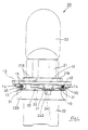
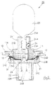
- a lamp body 10 of a rear combination lamp of an automobile is of plastic and plate like. Circular attachment holes 11 are provided on a plurality of prescribed locations on the lamp body 10 (only one location is shown in the present embodiment), a bulb socket 20 being inserted in the attachment hole 11 from the exterior.
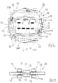
- Four electric wires 30 are distributed along the edges of the attachment hole 11 on a posterior face of the lamp body 10 (the lower face in Figure 1, and the face shown in Figure 3). When the bulb socket 20 is attached, contact members 24D thereof and core wires 31 of the electric wires 30 make contact and an electrically conductive state is achieved.
- the electric wire 30 comprises a core wire 30 made from separate metal filaments and covered with a plastic covering 32. A prescribed length of the plastic covering 32 is removed, this length corresponding to a core wire receiving member 13, to be described later. The core wire 31 is thus in an exposed state, and this exposed core wire 31 makes contact with the contact members 24D of the bulb socket 20.
- a total of four electric wire contact members 24C are provided. Their protruding end portions, which protrude towards the outer circumference of the flange 22B and make contact with the electric wire 30, constitute members 24D. These contact members 24D are provided at a pitch of 90° in the circumferential direction.
- the diameter of this groove is approximately the same as the diameter of the core wire 31 and the posterior semi-circle of the core wire 31 protrudes from the posterior side face of the ribs 12 when the core wire 31 is attached to the core wire receiving members 13.
- Supporting members 14 also protrude from the posterior face of the lamp body 10, these supporting members 14 being located on both sides of the core wire receiving member 13 along the direction in which the electric wire extends.
- Each supporting member 14 comprises a pair of mutually opposing protrusions 15 which clamp a portion of the plastic covering 32 of the electric wire 30.
- the opposing faces of the two protrusions 15 are cut away in a wedge-shape, forming protruding indenting members 16.
- the space between these indenting members 16 is slightly smaller than the external diameter of the plastic covering 32.
- a body 10 has an attachment hole 11, a bulb socket 20 being attached by being passed wherethrough.
- Four ribs 42 protrude from a posterior face of the body 10 (the side face in Figure 1, and the face shown in Figure 2), the ribs 42 protruding at a location slightly separated from an edge of the attachment hole 11.
- the four ribs 42 are provided at a 90° pitch along a circular path concentric with the attachment hole 11.
- Each rib 42 protrudes in an elliptic cylindrical shape, the length-wise axis thereof being parallel to the direction of the attachment hole 11.
- a pair of stopping members 43 are formed on the protruding edge of the rib 42, these stopping members 43 extending towards the outer circumference from the parallel edges of the ribs 42.
Landscapes
- Connecting Device With Holders (AREA)
- Connector Housings Or Holding Contact Members (AREA)
- Arrangement Of Elements, Cooling, Sealing, Or The Like Of Lighting Devices (AREA)
Applications Claiming Priority (4)
| Application Number | Priority Date | Filing Date | Title |
|---|---|---|---|
| JP4400298 | 1998-02-25 | ||
| JP10044002A JPH11242973A (ja) | 1998-02-25 | 1998-02-25 | バルブソケットと電線の接続構造 |
| JP10181093A JP2000012180A (ja) | 1998-06-26 | 1998-06-26 | バルブソケットと電線の接続構造 |
| JP18109398 | 1998-06-26 |
Publications (2)
| Publication Number | Publication Date |
|---|---|
| EP0939460A2 true EP0939460A2 (fr) | 1999-09-01 |
| EP0939460A3 EP0939460A3 (fr) | 2000-09-20 |
Family
ID=26383842
Family Applications (1)
| Application Number | Title | Priority Date | Filing Date |
|---|---|---|---|
| EP99300492A Withdrawn EP0939460A3 (fr) | 1998-02-25 | 1999-01-22 | Structure de connexion pour douille d'ampoule et un fil électrique |
Country Status (3)
| Country | Link |
|---|---|
| US (1) | US6296529B2 (fr) |
| EP (1) | EP0939460A3 (fr) |
| CN (1) | CN1238582A (fr) |
Cited By (2)
| Publication number | Priority date | Publication date | Assignee | Title |
|---|---|---|---|---|
| WO2007119923A1 (fr) * | 2006-04-14 | 2007-10-25 | Shin Kwang Hi Tech Co., Ltd. | Douille pour ampoule |
| CN115939786A (zh) * | 2023-01-06 | 2023-04-07 | 安徽迅普科技有限公司 | 一种电动汽车内部高压连接用电缆 |
Families Citing this family (9)
| Publication number | Priority date | Publication date | Assignee | Title |
|---|---|---|---|---|
| DE10163055B4 (de) * | 2001-12-21 | 2004-07-08 | Bjb Gmbh & Co.Kg | Lampenfassung, insbesondere Fassung für Halogen-Hochvoltlampen |
| DE10163057B4 (de) * | 2001-12-21 | 2004-07-08 | Bjb Gmbh & Co.Kg | Fassung für Hochvoltlampen |
| DE10163056B4 (de) * | 2001-12-21 | 2004-07-08 | Bjb Gmbh & Co.Kg | Lampenfassung |
| KR100791533B1 (ko) * | 2006-04-14 | 2008-01-04 | 주식회사 신광하이테크 | 전구 소켓 |
| JP2008021607A (ja) * | 2006-07-14 | 2008-01-31 | Nec Lighting Ltd | 放電灯の接続構造体および照明装置 |
| US7165990B1 (en) * | 2006-07-31 | 2007-01-23 | Osram Sylvania Inc. | Lamp socket with novel wire connector |
| US7731545B1 (en) * | 2009-02-25 | 2010-06-08 | Osram Sylvania Inc. | Lamp socket and contact for said socket |
| CN104482479A (zh) * | 2014-12-22 | 2015-04-01 | 江苏洪昌科技股份有限公司 | 一种汽车信号灯用灯泡座 |
| JP6903331B2 (ja) * | 2018-03-29 | 2021-07-14 | 北川工業株式会社 | コンタクト及びその製造方法 |
Citations (1)
| Publication number | Priority date | Publication date | Assignee | Title |
|---|---|---|---|---|
| JPH09231814A (ja) | 1996-02-26 | 1997-09-05 | Koito Mfg Co Ltd | 車輌用灯具 |
Family Cites Families (15)
| Publication number | Priority date | Publication date | Assignee | Title |
|---|---|---|---|---|
| US3050705A (en) * | 1959-07-14 | 1962-08-21 | United Carr Fastener Corp | Electrical assembly |
| DE1489578C3 (de) | 1965-06-04 | 1975-02-06 | Union Sils Van De Loo & Co, 5758 Froendenberg | Glühlampenfassung |
| US3397379A (en) * | 1965-10-20 | 1968-08-13 | Puig Juan Coma | Lamp socket with insulation piercing contacts |
| US3407377A (en) | 1967-06-29 | 1968-10-22 | Electrolux Corp | Electric cord set having a stress relieving plug |
| US3576516A (en) | 1968-11-13 | 1971-04-27 | Radiation Systems Inc | Quick connect-quick disconnect electrical connector |
| GB1434051A (en) * | 1973-02-22 | 1976-04-28 | Gen Electric Co Ltd | Electric socket connectors |
| US4076358A (en) * | 1977-03-28 | 1978-02-28 | Essex Group, Inc. | Lamp socket for printed circuit |
| US4193653A (en) * | 1978-01-20 | 1980-03-18 | Stanley Electric Co., Ltd. | Socket for mounting an electric lamp on a printed circuit board |
| GB2035722B (en) * | 1978-10-23 | 1983-03-02 | Tokyo Shibaura Electric Co | Lamp holder for baseless lamp |
| US4468585A (en) | 1982-03-18 | 1984-08-28 | Gte Products Corporation | Wedge base lamp socket |
| US4593958A (en) | 1984-05-04 | 1986-06-10 | Kabushiki Kaisha Toshiba | Socket for baseless lamp |
| US5015197A (en) | 1990-05-30 | 1991-05-14 | Amp Incorporated | Electrical connector and cable utilizing spring grade wire |
| NL9300386A (nl) | 1992-09-23 | 1994-10-03 | Whitaker Corp | Electrische connector en electrische aansluitklem daarvoor. |
| US5339232A (en) * | 1993-01-12 | 1994-08-16 | Lin Te H | Miniature light set |
| US5890912A (en) * | 1996-09-11 | 1999-04-06 | Cooper Automotive Products, Inc. | Contact terminal with linear contact region |
-
1999
- 1999-01-22 EP EP99300492A patent/EP0939460A3/fr not_active Withdrawn
- 1999-02-10 CN CN99100717A patent/CN1238582A/zh active Pending
-
2000
- 2000-12-18 US US09/738,775 patent/US6296529B2/en not_active Expired - Fee Related
Patent Citations (1)
| Publication number | Priority date | Publication date | Assignee | Title |
|---|---|---|---|---|
| JPH09231814A (ja) | 1996-02-26 | 1997-09-05 | Koito Mfg Co Ltd | 車輌用灯具 |
Cited By (2)
| Publication number | Priority date | Publication date | Assignee | Title |
|---|---|---|---|---|
| WO2007119923A1 (fr) * | 2006-04-14 | 2007-10-25 | Shin Kwang Hi Tech Co., Ltd. | Douille pour ampoule |
| CN115939786A (zh) * | 2023-01-06 | 2023-04-07 | 安徽迅普科技有限公司 | 一种电动汽车内部高压连接用电缆 |
Also Published As
| Publication number | Publication date |
|---|---|
| US6296529B2 (en) | 2001-10-02 |
| CN1238582A (zh) | 1999-12-15 |
| EP0939460A3 (fr) | 2000-09-20 |
| US20010000766A1 (en) | 2001-05-03 |
Similar Documents
| Publication | Publication Date | Title |
|---|---|---|
| US7794132B2 (en) | Lighting system | |
| EP2700128B1 (fr) | Garniture de borne | |
| EP1006613B1 (fr) | Broche de contact améliorée en deux parties | |
| US5399110A (en) | Two piece male pin terminal | |
| US6296529B2 (en) | Bulb socket and connection construction of wire | |
| US5035643A (en) | Axial low profile lamp socket assembly | |
| US20100062641A1 (en) | Coaxial connector | |
| GB2030794A (en) | Two-piece socket terminal | |
| US4842541A (en) | Electrical connector | |
| JP7487696B2 (ja) | コネクタ | |
| US7192315B2 (en) | Terminals for bulb sockets | |
| US20030068929A1 (en) | Wedge base sealed lamp socket | |
| JP3615551B2 (ja) | ランプ | |
| US6461027B1 (en) | Rear combination lamp | |
| US6206709B1 (en) | High voltage terminal for an ignition cable | |
| US6322401B2 (en) | Electrical connector having contact orientation features | |
| US4958429A (en) | Method of making low profile lamp socket assembly | |
| US5785560A (en) | Ignition cable connection terminal | |
| US6464539B2 (en) | Lamp fitting structure | |
| US11296438B1 (en) | Electrical connector assembly having a terminal-less connection system | |
| US5532443A (en) | Pressure contact terminal | |
| JPH0378754B2 (fr) | ||
| KR20050084235A (ko) | 케이블 커넥터 및 이러한 커넥터를 조합하기 위한 방법 | |
| US5597327A (en) | Spring terminal and method for making a spring terminal | |
| JPS5844553Y2 (ja) | ウエツジベ−スバルブ用保持構造 |
Legal Events
| Date | Code | Title | Description |
|---|---|---|---|
| PUAI | Public reference made under article 153(3) epc to a published international application that has entered the european phase |
Free format text: ORIGINAL CODE: 0009012 |
|
| 17P | Request for examination filed |
Effective date: 19990224 |
|
| AK | Designated contracting states |
Kind code of ref document: A2 Designated state(s): DE FR GB IT |
|
| AX | Request for extension of the european patent |
Free format text: AL;LT;LV;MK;RO;SI |
|
| PUAL | Search report despatched |
Free format text: ORIGINAL CODE: 0009013 |
|
| AK | Designated contracting states |
Kind code of ref document: A3 Designated state(s): AT BE CH CY DE DK ES FI FR GB GR IE IT LI LU MC NL PT SE |
|
| AX | Request for extension of the european patent |
Free format text: AL;LT;LV;MK;RO;SI |
|
| AKX | Designation fees paid |
Free format text: DE FR GB IT |
|
| 17Q | First examination report despatched |
Effective date: 20010718 |
|
| GRAG | Despatch of communication of intention to grant |
Free format text: ORIGINAL CODE: EPIDOS AGRA |
|
| STAA | Information on the status of an ep patent application or granted ep patent |
Free format text: STATUS: THE APPLICATION IS DEEMED TO BE WITHDRAWN |
|
| 18D | Application deemed to be withdrawn |
Effective date: 20020801 |