EP0940160B1 - Schneesportgerät - Google Patents
Schneesportgerät Download PDFInfo
- Publication number
- EP0940160B1 EP0940160B1 EP99410015A EP99410015A EP0940160B1 EP 0940160 B1 EP0940160 B1 EP 0940160B1 EP 99410015 A EP99410015 A EP 99410015A EP 99410015 A EP99410015 A EP 99410015A EP 0940160 B1 EP0940160 B1 EP 0940160B1
- Authority
- EP
- European Patent Office
- Prior art keywords
- pad
- vehicle according
- sliding
- seat
- support element
- Prior art date
- Legal status (The legal status is an assumption and is not a legal conclusion. Google has not performed a legal analysis and makes no representation as to the accuracy of the status listed.)
- Expired - Lifetime
Links
- 239000000725 suspension Substances 0.000 claims description 14
- 230000035939 shock Effects 0.000 claims description 13
- 229920001971 elastomer Polymers 0.000 claims description 8
- 239000006096 absorbing agent Substances 0.000 claims description 4
- 230000000750 progressive effect Effects 0.000 claims description 4
- 239000000806 elastomer Substances 0.000 claims description 3
- 239000000463 material Substances 0.000 claims description 3
- 230000000903 blocking effect Effects 0.000 claims 1
- 210000002414 leg Anatomy 0.000 description 8
- 238000013016 damping Methods 0.000 description 7
- 239000002184 metal Substances 0.000 description 3
- 230000006835 compression Effects 0.000 description 2
- 238000007906 compression Methods 0.000 description 2
- 230000000694 effects Effects 0.000 description 2
- 239000002023 wood Substances 0.000 description 2
- 241001415961 Gaviidae Species 0.000 description 1
- 230000001154 acute effect Effects 0.000 description 1
- 238000005452 bending Methods 0.000 description 1
- 239000002131 composite material Substances 0.000 description 1
- 230000005489 elastic deformation Effects 0.000 description 1
- 210000000629 knee joint Anatomy 0.000 description 1
- 238000004519 manufacturing process Methods 0.000 description 1
- 229910001092 metal group alloy Inorganic materials 0.000 description 1
- 239000002991 molded plastic Substances 0.000 description 1
- 210000000056 organ Anatomy 0.000 description 1
- 230000000284 resting effect Effects 0.000 description 1
- 238000007790 scraping Methods 0.000 description 1
- 125000006850 spacer group Chemical group 0.000 description 1
Images



Classifications
-
- B—PERFORMING OPERATIONS; TRANSPORTING
- B62—LAND VEHICLES FOR TRAVELLING OTHERWISE THAN ON RAILS
- B62B—HAND-PROPELLED VEHICLES, e.g. HAND CARTS OR PERAMBULATORS; SLEDGES
- B62B13/00—Sledges with runners
- B62B13/02—Sledges with runners characterised by arrangement of runners
- B62B13/04—Sledges with runners characterised by arrangement of runners arranged in a single line
- B62B13/043—Sledges with runners characterised by arrangement of runners arranged in a single line having one single runner
-
- B—PERFORMING OPERATIONS; TRANSPORTING
- B62—LAND VEHICLES FOR TRAVELLING OTHERWISE THAN ON RAILS
- B62B—HAND-PROPELLED VEHICLES, e.g. HAND CARTS OR PERAMBULATORS; SLEDGES
- B62B15/00—Other sledges; Ice boats or sailing sledges
Definitions
- a device well known under the name "PARET” is made entirely of wood by mortise bolt assembly of the seat and handle on the skate. In the normal driving position, the single pad slides on the snow, and just pull on the handle to raise the game front of the shoe, causing a braking effect on the rear.
- the structure monobloc of this device has a large footprint and weight, this which does not facilitate its transport.
- Another disadvantage is the lack of any effect damping in case of shocks collected during a descent.
- Document FR-A-2000 762 relates to a sledge sledge, comprising a bowl-shaped seat directly in contact with the snow, and a lever of steering protruding upwards.
- a sledge sledge comprising a bowl-shaped seat directly in contact with the snow, and a lever of steering protruding upwards.
- Such a device is nevertheless difficult to manage, given the low height of the seat relative to the ground, and the width of the skate that do not allow tilting the device to make it change course otherwise than by driving it like a classic sled, ie by braking with the foot located inside the bend.
- the document WO95 / 16504 describes an apparatus allowing the practice of alpine skiing at a disabled skier with legs.
- the apparatus includes a sole coupled to a ski alpine, and a support arm of a seat, which is hinged at the front on a tilting axis. Balance and driving is done with the help of the skier's arms, a small ski being mounted at the end of each of the two sticks, and taking support on the track according to a predetermined orientation in turns.
- a spring telescopic damper allows you to cash out mechanical shocks during skiing. Such a device is very heavy, and is not suitable for easily transported by the user.
- Document CH-A-537198 describes a ski-bob equipped with two skis connected to the frame by two articulated arms and shock absorbers with elastic deformation.
- US-A-3917301 discloses a monoski having a seat forming a part independent of the support member, and being articulated to the latter by two joints at the front and rear.
- the support element is formed of other two pivoting levers according to a compass system, presenting a complex structure.
- the object of the invention is to provide a slippery vehicle for snow sports, can be easily transported, and enjoying optimum comfort of suspension.
- the sliding vehicle according to the invention is characterized in that the intermediate portion of the support element constitutes said seat, which is secured and extended to the front by the driving organ, thus forming a body with the latter.
- the support element is connected to the skid by a mechanical connection, making it possible to fold down the support element against the pad in the storage and transport position.
- the mechanical connection can be disconnectable at one of its ends, or be formed by a knee joint with folding links according to branches a compass.
- the mechanical connection can also be formed by telescopic links.
- the mechanical connection comprises a articulated link on an axis of the shoe, and having an opposite end cooperating with control means likely to lock the rod in an active position to obtain an angular offset of the support element with respect to the pad, or to unlock the link for break the mechanical connection during storage.
- the disconnectable end of the link is advantageously provided with an axle held in position locked at the bottom of a notch of the support element by means of a lock.
- the mechanical link is equipped of a damper element allowing a relative movement of the element of support with respect to the pad.
- the damping member may be formed by a suspension spring, or a combined spring-oleo-pneumatic shock absorber or hydraulic, which is optionally equipped with an adjusting device manual prestressing or hardness. It is also possible to do use of an element of elastically deformable material, in particular rubber or elastomer.
- a braking member is arranged at the rear of the pad, and the surface of slip of the pad has at least one convex shaped portion or concave in the transverse direction, and an extension to extend the pad rearward.
- the vehicle comprises a Footrest device arranged at the front of the mechanical link and under the level of the seat, being secured to an extension of the support element, or with the spatula raised from the skate.
- the support element is equipped with at least one opening to constitute a handle, and / or a shoulder strap to facilitate the transport of the vehicle.
- the slippery vehicle advantageously comprises means of securing the pilot on the seat.
- the pad advantageously comprises at least two lateral bearing surfaces and sliding over at least a portion of the length of the pad, and arranged symmetrically on either side of a central surface while being offset in the vertical direction relative thereto.
- the support and sliding surface of the pad comprises at least two surfaces arranged symmetrically with respect to the vertical plane of symmetry of the vehicle, in two intersecting planes forming a dihedral open towards the top.
- the seat is connected to the skid by means of a mechanical link with two axes of articulation, the damping member comprising a system of elastic stops with progressive deformation, arranged respectively on the upper face of the pad in front of the axis articulation, and under the seat on either side of a leg of said link.
- the seat is hinged to the pad around axle, the suspension being ensured by means of a stop at progressive elasticity, fixed on the upper face of the pad and cooperating with a support plate housed in a lower face of the seat, said plate being adjustable for adjustment of seat inclination and prestressing of stop.
- a sliding vehicle 10 for snow sports has a single sliding shoe 12 bearing on the snow, and a support member 14 articulated on the sliding shoe 12 about an axis 16 perpendicular to the direction longitudinal.
- the pad 12 has a short ski shape having a width greater than 5 cm, and less than 140 cm in length.
- the front part of the pad 12 constitutes a spatula 18 raised upwards in the direction of sliding, while the rear part has an braking system 20 may brake the vehicle 10 downhill following a manual command.
- the intermediate part of the support element 14 is arranged in seat 22, which is extended forwardly by a driving member 24 disposed between the user's legs when the user is in a sitting position on the seat 22.
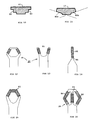
- the driver 24 comprises for example a handlebar 26 to two gripping handles 28, 30 (FIG. 3) separated from one another by a central branch 32.
- the base 34 of the support element 14 is mounted to pivoting on the transverse axis 16 at the rear of the pad 12.
- the front of the support element 14 is connected to the pad 12 by a link mechanical 35 comprising a link 36 articulated on an axis 38 of the pad 12, and having an opposite end 40 disconnectable from the support member 14.
- a link mechanical 35 comprising a link 36 articulated on an axis 38 of the pad 12, and having an opposite end 40 disconnectable from the support member 14.
- the upper end of the connecting rod 40 36 is locked to form a rigid spacer link, whereby the support member 14 is angularly offset from the pad 12 by an angle acute.
- the intermediate portion of the support member 14 is provided with at least one opening 42 offset laterally of the longitudinal axis 44 to form a handle to facilitate transport in the inactive folded position (figure 3).
- the intermediate portion of the shoe 12 has a boss 46 of substantially trapezoidal section, cooperating with a recess 48 of shape conjugate of the link 36 when stored on the pad 12.
- the disconnectable end 40 of the rod 36 of connection of Figure 1 has an axis 50 maintained at the bottom of a notch 52 U-shaped support member 14 by means of a telescopic latch 52.
- the lock 52 is provided with a retaining arm 54 preventing the escape of the axis 50, and an internal spring 56 biasing the latch 52 to the locked position in the connection area of the front of the seat 22 with the body of 24.
- the manual movement of the lock 52 in the direction of the arrow F1 against the restoring force of the spring 56 causes the withdrawal of the arm 54, and the release of the axis 50. It is then possible to fold the link 36, and bring back the support element 14 to the inactive position illustrated in FIG.
- the connecting rod 36 is associated with a damping member 58 allowing a limited bending of the support member 14 (arrow F3) in according to the weight of the driver, and the mechanical shocks collected by the vehicle 10 downhill.
- the damping member 58 is formed by way of example by a compression metal spring, or a shock absorber spring combination whose prestressing is advantageously adjustable by means of a device manual adjustment device 60, for example using a rack stop or cam. Any other suspension member may be used, in particular a deformable rubber or elastomer pad or damper olepneumatic or hydraulic.
- the upper end 40 of the damping member 58 is disconnectable from the support member 14 to allow folding and storing the assembly to the inactive position.
- the vehicle 10 may be equipped in addition to a footrest device 62 mounted at the front of the mechanical linkage.
- the device footrest 62 is constituted either by an extension 64 prior to the support element 14 (FIG. 8), or by an integral transverse bar 66 spatula 18 ( Figure 9).
- the extension 64 or the bar 66 of the footrest device 62 fixed is arranged in the anterior area below the level of the seat 22, and above the sliding pad 12.
- the sliding surface of the pad 12 on the snow may be either flat or with slightly concave or convex zones.
- Metal edges may be provided on at least part of the length of the sides side of the sliding face.
- the rear part comprises advantageously a metal sole extending over the entire width of the pad 12, and ending with a squeegee of the braking member 20.
- the body of the pad 12 and the support element 14 is made of either wood or material molded plastic, either of composite material or metal alloy.
- the sliding surface 80 of the shoe 12 is subdivided into a plurality of stepped staggered bearing surfaces in the vertical direction for adjust the vehicle depression according to the snow conditions.
- the songs side of the sliding shoe 12 may be rectilinear and parallel to the longitudinal axis, or slightly concave or convex shapes in the intermediate part.
- the stands are replaced by oblique bearing surfaces 80a, 80b making an obtuse angle with each other in two intersecting planes forming a dihedral open upwards.
- the driving member 24 may be shaped according to other modes of production.
- the driving member corresponds to the handlebar of the Figure 3, but without central branch.
- the handlebar constitutes a fork-shaped open loop 81 arranged symmetrically with respect to at the median longitudinal plane.
- a handle 82, 83 unique is respectively on the vertical or horizontal branch higher.
- the driving member 24 comprises three branches with handles 84, 85, 86.
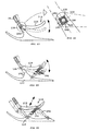
- the seat 116 is pivotally mounted limited on the connecting leg 190 by means of an elastic connection formed by less a hinge 126 causing the automatic recall of the element of support 114 to the initial position (in strong lines in Figure 17).
- the element support 114 is cantilevered on the front of the shoe 112, and the hinge 126 extends transversely to the direction longitudinal of the pad 112.
- the hinge 126 comprises a plurality of blocks 178, 180, 182, 184 prestressed rubber arranged between the four faces of a first tube 186 square, and the four angles of a second tube Square, the first tube 186 being concentrically disposed within the second tube 188.
- an additional damping member 192 is advantageously articulated between the median part of the pad 112, and the rear part of the element support 114 by making a V with the leg 190.
- a link 194 is articulated at the rear of the support element 114 and the shoe 112 extending parallel to the leg 190.
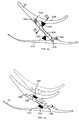
- the seat 216 is connected to the shoe 212 by means of a mechanical link 290 with two hinge pins 238, 240.
- the body spring damper 58 of the device of FIGS. 7 and 8 is replaced by a system of elastic stops 242, 244 with progressive deformation, and conical shapes.
- the bottom stop 242 is disposed on the upper face of the shoe 212 in front of the hinge pin 238, while the stop 244 is arranged under the seat 216.
- a torsion spring 246, 248 is threaded about each axis 238, 240, and the leg of the mechanical link 290 is interposed between the two abutments 242, 244, which deform by compression when passing the seat 216 from the dotted position to the position in strong lines (figure 22).
- the stop 244 is placed opposite a support plate 250 of connection 290. The support plate 250 is retracted into the position inactive folded ( Figure 23), so as to allow the passage of the stop 244 ( Figure 25).
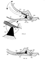
- the seat 316 is hinged around a transverse axis 316 at the rear of the shoe 312, and the suspension is ensured by means of a conically elastic stop 342 fixed on the upper face of the shoe 312.
- a support plate 350 is housed in a groove 352 longitudinal under the underside of the seat 316, and cooperates with the stop 342 during the suspension movement of the seat 316.
- the backing plate 350 has a stepped end 354 allowing the times the adjustment of the inclination of the seat 316 with respect to the shoe 312, and the prestressing the stop 342 to dose the suspension.
- the torsion spring 356 about the axis 316 maintains the seat 316 folded against the shoe 312.
- the support element may be equipped with a pair of straps (no shown) to facilitate transportation of the vehicle 10 by hand or on the back.
Landscapes
- Engineering & Computer Science (AREA)
- Chemical & Material Sciences (AREA)
- Combustion & Propulsion (AREA)
- Transportation (AREA)
- Mechanical Engineering (AREA)
- Passenger Equipment (AREA)
- Vehicle Body Suspensions (AREA)
- Footwear And Its Accessory, Manufacturing Method And Apparatuses (AREA)
Claims (23)
- Gleitfahrzeug zum Fahren im Schnee, das umfasst:dadurch gekennzeichnet, dass ein Zwischenteil des Stützelements (14, 114) den Sitz bildet, der fest mit der Lenkeinrichtung (24, 26) verbunden und nach vorne durch diese verlängert ist.einen Gleitschuh (12, 112, 212, 312), der auf dem Schnee aufliegt,einen Sitz (22, 116, 216, 316), auf dem der Fahrer Platz nimmt,ein Stützelement (14, 114), das bezüglich dem Gleitschuh (12, 112, 212, 312) gelenkig um eine Querachse (16, 126, 238, 316) gelagert ist, die sich lotrecht zur Symmetrieebene des Fahrzeugs erstreckt,und eine manuell bediente Lenkvorrichtung (24, 26) zum Steuern und Bremsen des Fahrzeugs, welche Einrichtung mit einem Stützelement (14, 114) verbunden und so aufgebaut ist, dass sie zumindest einen Griff oder Lenker umfasst, der sich, wenn der Fahrer auf dem Sitz sitzt (22, 116, 216, 316), zwischen dessen Beinen vor dem Sitz und in Gleitrichtung befindet,
- Gleitfahrzeug nach Anspruch 1, dadurch gekennzeichnet, dass das Stützelement (14) mit dem Gleitschuh (12) über eine mechanische Verbindung (35) verbunden ist, die in einer Lagerungs- und Transportposition ein Umklappen des Stützelements (14) zum Gleitschuh (12) hin erlaubt.
- Gleitfahrzeug nach Anspruch 2, dadurch gekennzeichnet, dass die mechanische Verbindung (35) an einem ihrer Enden lösbar ist.
- Gleitfahrzeug nach Anspruch 2, dadurch gekennzeichnet, dass die mechanische Verbindung (35) von einem beweglichen Gelenk mit umklappbaren Stangen wie den Armen eines Zirkels gebildet wird.
- Gleitfahrzeug nach Anspruch 2, dadurch gekennzeichnet, dass die mechanische Verbindung (35) einen Schwingarm (36) umfasst, der an eine Achse (38) des Gleitschuhs (12) angelenkt ist und ein entgegengesetztes Ende (40) hat, das mit Steuerungsvorrichtungen zusammenwirkt, die den Schwingarm (36) entweder in einer aktiven Position zum Erreichen einer Winkelversetzung des Stützelements (14) zum Gleitschuh (12) verriegeln oder den Schwingarm (36) freigeben, um die mechanische Verbindung (35) zu lösen, wenn das Fahrzeug verstaut wird.
- Gleitfahrzeug nach Anspruch 5, dadurch gekennzeichnet, dass das lösbare Ende (40) des Schwingarms (36) mit einem Bolzen (50) versehen ist, der mittels eines Riegels (52) in verriegelter Position in einer Ausnehmung (52) des Stützelements (14) gehalten wird.
- Gleitfahrzeug nach einem der Ansprüche 1 bis 6, dadurch gekennzeichnet, dass es eine stoßdämpfende Einrichtung (58, 192, 244, 242, 342) umfasst, die eine Drehbewegung des Stützelements (14, 114) bezüglich dem Gleitschuh (12, 112, 212, 312) um die Achse (16, 126, 238, 316) erlaubt.
- Gleitfahrzeug nach Anspruch 7, dadurch gekennzeichnet, dass die stoßdämpfende Einrichtung (58) von einer Feder oder einer Kombination aus einer Feder und einem ölpneumatischen oder hydraulischen Stoßdämpfer oder einem Element aus elastisch verformbaren Material, insbesondere Gummi oder einem Elastomer, gebildet wird.
- Gleitfahrzeug nach Anspruch 7 oder 8, dadurch gekennzeichnet, dass es eine manuell gesteuerte Vorrichtung (60) zum Einstellen der mechanischen Vorspannung der stoßdämpfenden Einrichtung (58) umfasst.
- Gleitfahrzeug nach einem der Ansprüche 1 bis 9, dadurch gekennzeichnet, dass es Mittel zum Zurückholen und/oder Blockieren umfasst, die ein Halten des Stützelements (14) gegen den Gleitschuh (12) in der Stellung ermöglichen, in der das Fahrzeug verstaut und transportiert wird.
- Gleitfahrzeug nach einem der Ansprüche 1 bis 10, dadurch gekennzeichnet, dass es eine Bremseinrichtung (20) umfasst, die im hinteren Bereich des Gleitschuhs (12, 112, 212, 312) angeordnet ist.
- Gleitfahrzeug nach einem der Ansprüche 1 bis 11, dadurch gekennzeichnet, dass die Gleitfläche des Gleitschuhs (12) mittels eines Verlängerungsstücks (76) nach hinten verlängert werden kann.
- Gleitfahrzeug nach einem der Ansprüche 1 bis 12, dadurch gekennzeichnet, dass es eine Fußauflagevorrichtung (62, 66) umfasst, die sich vor der mechanischen Verbindung (35) und unter der Höhe des Sitzes (22) befindet und fest an einer Verlängerung (64) des Stützelements (14) oder an der angehobenen Schaufel (18) des Gleitschuhs (12) angebracht ist.
- Gleitfahrzeug nach einem der Ansprüche 1 bis 13, dadurch gekennzeichnet, dass das Stützelement (14) im Sitzbereich des Fahrers mindestens eine Öffnung (42) zur Bildung eines Griffs und/oder einen Tragegurt aufweist, um den Transport des Fahrzeugs (10) zu erleichtern.
- Gleitfahrzeug nach Anspruch 7, dadurch gekennzeichnet, dass die stoßdämpfende Einrichtung von einem Drehgelenk (126) gebildet wird, das mehrere vorgespannte Gummiblöcke (178, 180, 182, 184) umfasst, die zwischen den vier Seiten einer ersten quadratischen Röhre (186) und den vier Ecken einer zweiten quadratischen Röhre (188) vorgesehen sind, wobei die erste Röhre (186) konzentrisch innerhalb der zweiten Röhre (188) angeordnet ist.
- Gleitfahrzeug nach einem der Ansprüche 1 bis 15, dadurch gekennzeichnet, dass die entgegengesetzten Längskanten des Gleitschuhs (12) im Verlängerungsbereich des Sitzes (16) konkav sind.
- Gleitfahrzeug nach einem der Ansprüche 1 bis 16, dadurch gekennzeichnet, dass das Gelenk zwischen einem der Enden einer Verbindungsstrebe (90, 190, 290) zwischen dem Gleitschuh (12, 112, 212) und dem Stützelement (14, 114) angeordnet ist.
- Gleitfahrzeug nach Anspruch 17, dadurch gekennzeichnet, dass die stoßdämpfende Einrichtung (192) zwischen dem mittleren Bereich des Gleitschuhs (112) und dem hinteren Bereich des Stützelements (114) angeordnet ist, der mit der Strebe (190) ein V bildet.
- Gleitfahrzeug nach Anspruch 18, dadurch gekennzeichnet, dass hinter dem Stützelement (114) und dem Gleitschuh (112) ein Schwingarm (194) angelenkt ist, der sich parallel zur Strebe (190) erstreckt.
- Gleitfahrzeug nach einem der Ansprüche 1 bis 19, dadurch gekennzeichnet, dass der Gleitschuh (12, 112, 212, 312) mindestens zwei seitliche Auflageund Gleitflächen (80) aufweist, die sich über mindestens einen Teil der Länge des Gleitschuhs erstrecken und symmetrisch beidseits einer Mittelfläche angeordnet sind, dabei jedoch in senkrechter Richtung bezogen auf diese versetzt sind.
- Fahrzeug nach einem der Ansprüche 1 bis 19, dadurch gekennzeichnet, dass auf mindestens einem Teil der Länge des Gleitschuhs (12, 112, 212, 312) die Auflage- und Gleitfläche mindestens zwei Flächen (80a, 80b) aufweist, die bezogen auf die vertikale Symmetrieebene des Fahrzeugs symmetrisch angeordnet sind, und zwar auf zwei einander schneidenden Ebenen, die einen nach oben offenen Dieder bilden.
- Fahrzeug nach Anspruch 8, dadurch gekennzeichnet, dass der Sitz (216) mittels einer mechanischen Verbindung (290) mit zwei Gelenkachsen (240, 238) mit dem Gleitschuh (212) verbunden ist und dass die stoßdämpfende Vorrichtung ein System aus elastischen Anschlägen (242, 244) umfasst, die sich schrittweise verformen und jeweils auf der Oberseite des Gleitschuhs (212) vor der Gelenkachse (238) bzw. unter dem Sitz (216) beidseits einer Strebe dieser Verbindung (290) angeordnet sind.
- Fahrzeug nach Anspruch 8, dadurch gekennzeichnet, dass der Sitz (316) um eine Achse (316) an den Gleitschuh (312) angelenkt ist, wobei die Federung mittels eines schrittweise nachgebenden Anschlags (342) erfolgt, der auf der Oberseite des Gleitschuhs (312) angebracht ist und mit einer Auflageplatte (350) zusammenwirkt, die in einer Unterseite des Sitzes (316) untergebracht ist, wobei die Platte zur Einstellung der Neigung des Sitzes (316) und der Vorspannung des Anschlags (342) verstellbar ist.
Applications Claiming Priority (8)
| Application Number | Priority Date | Filing Date | Title |
|---|---|---|---|
| FR9803004 | 1998-03-06 | ||
| FR9803003 | 1998-03-06 | ||
| FR9803003A FR2775609B1 (fr) | 1998-03-06 | 1998-03-06 | Vehicule glissant pour sport de neige |
| FR9803004A FR2775610B1 (fr) | 1998-03-06 | 1998-03-06 | Vehicule glissant sur neige, equipe de moyens de suspension |
| FR9803005A FR2775611B3 (fr) | 1998-03-06 | 1998-03-06 | Vehicule glissant a patin perfectionne pour sport de neige |
| FR9803005 | 1998-03-06 | ||
| CA002270296A CA2270296C (fr) | 1998-03-06 | 1999-04-26 | Vehicule glissant pour sport de neige |
| US09/657,323 US6416065B1 (en) | 1998-03-06 | 2000-09-07 | Sliding vehicle for snow sport |
Publications (2)
| Publication Number | Publication Date |
|---|---|
| EP0940160A1 EP0940160A1 (de) | 1999-09-08 |
| EP0940160B1 true EP0940160B1 (de) | 2005-06-01 |
Family
ID=32097089
Family Applications (1)
| Application Number | Title | Priority Date | Filing Date |
|---|---|---|---|
| EP99410015A Expired - Lifetime EP0940160B1 (de) | 1998-03-06 | 1999-03-05 | Schneesportgerät |
Country Status (3)
| Country | Link |
|---|---|
| US (1) | US6416065B1 (de) |
| EP (1) | EP0940160B1 (de) |
| CA (1) | CA2270296C (de) |
Families Citing this family (8)
| Publication number | Priority date | Publication date | Assignee | Title |
|---|---|---|---|---|
| EP0940160B1 (de) | 1998-03-06 | 2005-06-01 | Jean-Claude Bibollet | Schneesportgerät |
| WO2003068341A2 (en) * | 2002-01-21 | 2003-08-21 | Wham-O, Inc. | Snow recreation device |
| US20050029758A1 (en) * | 2003-08-06 | 2005-02-10 | Ohler Robert D. | Snow sled |
| DE202004011094U1 (de) * | 2004-07-13 | 2005-03-31 | Topsport Gmbh Windsurf Faszina | Gefederter und zusammenlegbarer Rodelschlitten |
| FR2912982B1 (fr) * | 2007-02-26 | 2009-07-31 | Corentin Desbois | Dispositif de deplacement sur neige |
| US20090014995A1 (en) * | 2007-07-13 | 2009-01-15 | Rockit Ski, Llc | Seated skiing or snowboarding device |
| US7922206B2 (en) * | 2008-04-30 | 2011-04-12 | James Kriezel | Upright seated snowboard |
| CN106143583A (zh) * | 2015-03-27 | 2016-11-23 | 中国科学院沈阳自动化研究所 | 一种雪橇悬架机构 |
Citations (3)
| Publication number | Priority date | Publication date | Assignee | Title |
|---|---|---|---|---|
| US2062953A (en) * | 1935-03-13 | 1936-12-01 | Louis W Wargo | Sled |
| CH537198A (fr) * | 1971-02-06 | 1973-05-31 | Evequoz Jean Yves | Ski-bob |
| US3917301A (en) * | 1972-05-20 | 1975-11-04 | Sergio Fabris | Snow monoski |
Family Cites Families (27)
| Publication number | Priority date | Publication date | Assignee | Title |
|---|---|---|---|---|
| US1672782A (en) * | 1928-06-05 | Coaster | ||
| AT42200B (de) * | 1909-04-24 | 1910-05-10 | Ottomar Deckert | Rodelschlitten. |
| US3014731A (en) * | 1960-02-15 | 1961-12-26 | Theodore A Dworak | Ski vehicle |
| CH477887A (de) * | 1967-12-15 | 1969-09-15 | Auer Josef | Schibob |
| DE1605877B1 (de) * | 1968-01-25 | 1970-11-19 | Johann Uttenthaler | Schlittenartige Rodelkufe |
| US3561783A (en) * | 1969-06-09 | 1971-02-09 | Richard H Ellett | Ski bike |
| GB1292379A (en) * | 1970-03-23 | 1972-10-11 | Johann Uttenthaler | Improvements in or relating to sleds |
| US3825360A (en) * | 1971-07-30 | 1974-07-23 | T Galich | Joint apparatus for sectioned skis or the like |
| US3897078A (en) * | 1972-04-27 | 1975-07-29 | Dennis M Melnick | Ski shovel |
| DE2257233A1 (de) * | 1972-11-22 | 1974-05-30 | Karl M Mayer | Schlitten fuer sportliche und/oder gewerbliche zwecke |
| US4324409A (en) * | 1980-08-15 | 1982-04-13 | Schmid Tool & Engineering Corp. | Sled body and adjustable attachment means for snow skis |
| EP0149953B1 (de) * | 1984-01-03 | 1989-03-22 | Pierre Perret | Skirodelschlitteneinrichtung |
| DE3513138A1 (de) * | 1985-04-12 | 1986-10-23 | Roland 8885 Holzheim Nowak | Schlitten |
| FR2592806A1 (fr) * | 1986-01-16 | 1987-07-17 | Vaschalde Andre | Siege adaptable pour skis a neige |
| FR2611515A1 (fr) * | 1986-12-05 | 1988-09-09 | Saint Martin Patrick | Dispositif permettant la pratique du ski en position assise sur monoski |
| FR2657533B1 (fr) * | 1990-01-29 | 1992-04-03 | Salomon Sa | Ski de fond pour patinage. |
| FR2665369B1 (fr) * | 1990-08-06 | 1992-10-16 | Salomon Sa | Ski a face superieure convexe variable. |
| CA2081852A1 (en) * | 1992-10-30 | 1994-05-01 | Wally Rauf | Snow luge |
| US5375868A (en) * | 1993-03-03 | 1994-12-27 | Sarver; Jeff | Ski having compound curve undersurface |
| US5469169A (en) | 1993-11-30 | 1995-11-21 | University Corporation For Atmospheric Research | Receiver for bistatic doppler radar network |
| US5516126A (en) * | 1995-03-10 | 1996-05-14 | Myers; Jeff D. | Snow ski or runner |
| US5673772A (en) * | 1995-10-16 | 1997-10-07 | Martin; Robert L. | Snowmobile braking system |
| US6179305B1 (en) * | 1997-03-07 | 2001-01-30 | Matthew V. Capozzi | Accessible seating assembly |
| DE29711581U1 (de) * | 1997-07-02 | 1997-08-28 | Stiebler, Manfred, 78183 Hüfingen | Schneesportgerät |
| US6019380A (en) * | 1997-09-30 | 2000-02-01 | Goodman; Michael L. | Adaptive monoski frame |
| US6036202A (en) * | 1997-12-02 | 2000-03-14 | Lacome; Kenneth Paul | Sit-ski |
| EP0940160B1 (de) | 1998-03-06 | 2005-06-01 | Jean-Claude Bibollet | Schneesportgerät |
-
1999
- 1999-03-05 EP EP99410015A patent/EP0940160B1/de not_active Expired - Lifetime
- 1999-04-26 CA CA002270296A patent/CA2270296C/fr not_active Expired - Fee Related
-
2000
- 2000-09-07 US US09/657,323 patent/US6416065B1/en not_active Expired - Fee Related
Patent Citations (3)
| Publication number | Priority date | Publication date | Assignee | Title |
|---|---|---|---|---|
| US2062953A (en) * | 1935-03-13 | 1936-12-01 | Louis W Wargo | Sled |
| CH537198A (fr) * | 1971-02-06 | 1973-05-31 | Evequoz Jean Yves | Ski-bob |
| US3917301A (en) * | 1972-05-20 | 1975-11-04 | Sergio Fabris | Snow monoski |
Also Published As
| Publication number | Publication date |
|---|---|
| CA2270296A1 (fr) | 2000-10-26 |
| US6416065B1 (en) | 2002-07-09 |
| CA2270296C (fr) | 2007-09-11 |
| EP0940160A1 (de) | 1999-09-08 |
Similar Documents
| Publication | Publication Date | Title |
|---|---|---|
| EP0617638B1 (de) | Einrichtung zur druckverteilung eines schis auf der gleitläche | |
| WO1993014837A1 (fr) | Dispositif pour modifier la repartition d'un ski sur sa surface de glisse | |
| EP1704077B1 (de) | Gleitvorrichtung für schneesportarten | |
| EP0940160B1 (de) | Schneesportgerät | |
| FR2642982A2 (fr) | Patin a roulettes dont la fixation comporte une tige universelle permettant l'utilisation quelle que soit la chaussure basse ou montante | |
| EP2689762B1 (de) | Gelände-Transportmittel für Menschen mit eingeschränkter Bewegungsfähigkeit | |
| CH673400A5 (de) | ||
| WO2016055746A1 (fr) | Vehicule de type trottinette | |
| FR2710275A1 (fr) | Dispositif de fauteuil à ski. | |
| FR2775609A1 (fr) | Vehicule glissant pour sport de neige | |
| FR2798072A1 (fr) | Perfectionnement pour vehicule glissant sur neige | |
| FR2770142A1 (fr) | Dispositif de fauteuil a skis, notamment pour un skieur handicape des jambes | |
| FR2614002A1 (fr) | Jouet mini-kart auto-propulseur | |
| FR2616341A1 (fr) | Dispositif de skis pour sport de glisse | |
| EP3756973B1 (de) | Gelände-transportvorrichtung für ein kind in sitzender position | |
| FR2775611A1 (fr) | Vehicule glissant a patin perfectionne pour sport de neige | |
| FR2775610A1 (fr) | Vehicule glissant sur neige, equipe de moyens de suspension | |
| FR2827248A1 (fr) | Vehicule de loisir destine a la descente des pistes enneigees | |
| FR2909630A1 (fr) | Vehicule glissant mono patin pour sport de neige | |
| EP1310275B1 (de) | Ski mit Sattel | |
| FR2601920A1 (fr) | Vehicule glissant dirigeable et freinable. | |
| FR2530153A1 (fr) | Dispositif de simulation des skis a neige | |
| CA2127159C (fr) | Bicyclette sur glace | |
| WO2015124842A1 (fr) | Traîneau | |
| WO1995011066A1 (fr) | Dispositif destine a diminuer la pression des extremites du ski sur la neige suivant l'appui du skieur sur le ski |
Legal Events
| Date | Code | Title | Description |
|---|---|---|---|
| PUAI | Public reference made under article 153(3) epc to a published international application that has entered the european phase |
Free format text: ORIGINAL CODE: 0009012 |
|
| AK | Designated contracting states |
Kind code of ref document: A1 Designated state(s): AT CH DE ES FR IT LI SE |
|
| AX | Request for extension of the european patent |
Free format text: AL;LT;LV;MK;RO;SI |
|
| 17P | Request for examination filed |
Effective date: 20000307 |
|
| AKX | Designation fees paid |
Free format text: AT CH DE ES FR IT LI SE |
|
| 17Q | First examination report despatched |
Effective date: 20030829 |
|
| GRAP | Despatch of communication of intention to grant a patent |
Free format text: ORIGINAL CODE: EPIDOSNIGR1 |
|
| GRAS | Grant fee paid |
Free format text: ORIGINAL CODE: EPIDOSNIGR3 |
|
| GRAA | (expected) grant |
Free format text: ORIGINAL CODE: 0009210 |
|
| AK | Designated contracting states |
Kind code of ref document: B1 Designated state(s): AT CH DE ES FR IT LI SE |
|
| PG25 | Lapsed in a contracting state [announced via postgrant information from national office to epo] |
Ref country code: IT Free format text: LAPSE BECAUSE OF FAILURE TO SUBMIT A TRANSLATION OF THE DESCRIPTION OR TO PAY THE FEE WITHIN THE PRESCRIBED TIME-LIMIT;WARNING: LAPSES OF ITALIAN PATENTS WITH EFFECTIVE DATE BEFORE 2007 MAY HAVE OCCURRED AT ANY TIME BEFORE 2007. THE CORRECT EFFECTIVE DATE MAY BE DIFFERENT FROM THE ONE RECORDED. Effective date: 20050601 |
|
| REG | Reference to a national code |
Ref country code: CH Ref legal event code: EP |
|
| REF | Corresponds to: |
Ref document number: 69925525 Country of ref document: DE Date of ref document: 20050707 Kind code of ref document: P |
|
| PG25 | Lapsed in a contracting state [announced via postgrant information from national office to epo] |
Ref country code: SE Free format text: LAPSE BECAUSE OF FAILURE TO SUBMIT A TRANSLATION OF THE DESCRIPTION OR TO PAY THE FEE WITHIN THE PRESCRIBED TIME-LIMIT Effective date: 20050901 |
|
| PG25 | Lapsed in a contracting state [announced via postgrant information from national office to epo] |
Ref country code: DE Free format text: LAPSE BECAUSE OF FAILURE TO SUBMIT A TRANSLATION OF THE DESCRIPTION OR TO PAY THE FEE WITHIN THE PRESCRIBED TIME-LIMIT Effective date: 20050902 |
|
| PG25 | Lapsed in a contracting state [announced via postgrant information from national office to epo] |
Ref country code: ES Free format text: LAPSE BECAUSE OF FAILURE TO SUBMIT A TRANSLATION OF THE DESCRIPTION OR TO PAY THE FEE WITHIN THE PRESCRIBED TIME-LIMIT Effective date: 20050912 |
|
| PLBE | No opposition filed within time limit |
Free format text: ORIGINAL CODE: 0009261 |
|
| STAA | Information on the status of an ep patent application or granted ep patent |
Free format text: STATUS: NO OPPOSITION FILED WITHIN TIME LIMIT |
|
| 26N | No opposition filed |
Effective date: 20060302 |
|
| REG | Reference to a national code |
Ref country code: FR Ref legal event code: TP |
|
| PGFP | Annual fee paid to national office [announced via postgrant information from national office to epo] |
Ref country code: CH Payment date: 20130312 Year of fee payment: 15 |
|
| PGFP | Annual fee paid to national office [announced via postgrant information from national office to epo] |
Ref country code: AT Payment date: 20130312 Year of fee payment: 15 |
|
| REG | Reference to a national code |
Ref country code: CH Ref legal event code: PL |
|
| REG | Reference to a national code |
Ref country code: AT Ref legal event code: MM01 Ref document number: 296672 Country of ref document: AT Kind code of ref document: T Effective date: 20140305 |
|
| PG25 | Lapsed in a contracting state [announced via postgrant information from national office to epo] |
Ref country code: LI Free format text: LAPSE BECAUSE OF NON-PAYMENT OF DUE FEES Effective date: 20140331 Ref country code: CH Free format text: LAPSE BECAUSE OF NON-PAYMENT OF DUE FEES Effective date: 20140331 |
|
| PG25 | Lapsed in a contracting state [announced via postgrant information from national office to epo] |
Ref country code: AT Free format text: LAPSE BECAUSE OF NON-PAYMENT OF DUE FEES Effective date: 20140305 |
|
| REG | Reference to a national code |
Ref country code: FR Ref legal event code: PLFP Year of fee payment: 17 |
|
| PGFP | Annual fee paid to national office [announced via postgrant information from national office to epo] |
Ref country code: FR Payment date: 20150325 Year of fee payment: 17 |
|
| REG | Reference to a national code |
Ref country code: FR Ref legal event code: ST Effective date: 20161130 |
|
| PG25 | Lapsed in a contracting state [announced via postgrant information from national office to epo] |
Ref country code: FR Free format text: LAPSE BECAUSE OF NON-PAYMENT OF DUE FEES Effective date: 20160331 |