EP0940255B1 - Dispositif de déplacement d'un fluide - Google Patents
Dispositif de déplacement d'un fluide Download PDFInfo
- Publication number
- EP0940255B1 EP0940255B1 EP19990420052 EP99420052A EP0940255B1 EP 0940255 B1 EP0940255 B1 EP 0940255B1 EP 19990420052 EP19990420052 EP 19990420052 EP 99420052 A EP99420052 A EP 99420052A EP 0940255 B1 EP0940255 B1 EP 0940255B1
- Authority
- EP
- European Patent Office
- Prior art keywords
- polymer
- jet head
- printing fluid
- external stress
- fluid
- Prior art date
- Legal status (The legal status is an assumption and is not a legal conclusion. Google has not performed a legal analysis and makes no representation as to the accuracy of the status listed.)
- Expired - Lifetime
Links
- 239000012530 fluid Substances 0.000 title claims description 79
- 229920000642 polymer Polymers 0.000 claims description 112
- 230000002209 hydrophobic effect Effects 0.000 claims description 40
- 238000007639 printing Methods 0.000 claims description 29
- 230000006355 external stress Effects 0.000 claims description 25
- 230000009471 action Effects 0.000 claims description 12
- 229920000620 organic polymer Polymers 0.000 claims description 4
- 230000035882 stress Effects 0.000 claims description 3
- 239000000976 ink Substances 0.000 description 84
- 238000010438 heat treatment Methods 0.000 description 20
- 230000007704 transition Effects 0.000 description 14
- -1 polyethylene Polymers 0.000 description 9
- 238000000034 method Methods 0.000 description 8
- 238000005516 engineering process Methods 0.000 description 6
- 230000008859 change Effects 0.000 description 5
- 229920003213 poly(N-isopropyl acrylamide) Polymers 0.000 description 4
- 230000003213 activating effect Effects 0.000 description 2
- 230000015572 biosynthetic process Effects 0.000 description 2
- 230000003247 decreasing effect Effects 0.000 description 2
- 230000005686 electrostatic field Effects 0.000 description 2
- 125000001165 hydrophobic group Chemical group 0.000 description 2
- 229920001600 hydrophobic polymer Polymers 0.000 description 2
- 230000005499 meniscus Effects 0.000 description 2
- 239000000178 monomer Substances 0.000 description 2
- 238000009834 vaporization Methods 0.000 description 2
- 230000008016 vaporization Effects 0.000 description 2
- 238000010146 3D printing Methods 0.000 description 1
- HRPVXLWXLXDGHG-UHFFFAOYSA-N Acrylamide Chemical compound NC(=O)C=C HRPVXLWXLXDGHG-UHFFFAOYSA-N 0.000 description 1
- 239000004698 Polyethylene Substances 0.000 description 1
- 230000018199 S phase Effects 0.000 description 1
- 230000008901 benefit Effects 0.000 description 1
- 230000000903 blocking effect Effects 0.000 description 1
- 238000001816 cooling Methods 0.000 description 1
- 238000009792 diffusion process Methods 0.000 description 1
- 238000001035 drying Methods 0.000 description 1
- 230000000694 effects Effects 0.000 description 1
- 150000002334 glycols Chemical class 0.000 description 1
- 230000017525 heat dissipation Effects 0.000 description 1
- 238000007641 inkjet printing Methods 0.000 description 1
- 239000007788 liquid Substances 0.000 description 1
- 238000004519 manufacturing process Methods 0.000 description 1
- 239000000463 material Substances 0.000 description 1
- FQPSGWSUVKBHSU-UHFFFAOYSA-N methacrylamide Chemical compound CC(=C)C(N)=O FQPSGWSUVKBHSU-UHFFFAOYSA-N 0.000 description 1
- 229920000573 polyethylene Polymers 0.000 description 1
- 230000008569 process Effects 0.000 description 1
- 230000004044 response Effects 0.000 description 1
- 229910052710 silicon Inorganic materials 0.000 description 1
- 239000010703 silicon Substances 0.000 description 1
- 230000007480 spreading Effects 0.000 description 1
- 239000004094 surface-active agent Substances 0.000 description 1
- 238000003786 synthesis reaction Methods 0.000 description 1
- 125000000391 vinyl group Chemical group [H]C([*])=C([H])[H] 0.000 description 1
- 229920002554 vinyl polymer Polymers 0.000 description 1
- 238000009736 wetting Methods 0.000 description 1
Images



Classifications
-
- B—PERFORMING OPERATIONS; TRANSPORTING
- B41—PRINTING; LINING MACHINES; TYPEWRITERS; STAMPS
- B41J—TYPEWRITERS; SELECTIVE PRINTING MECHANISMS, i.e. MECHANISMS PRINTING OTHERWISE THAN FROM A FORME; CORRECTION OF TYPOGRAPHICAL ERRORS
- B41J2/00—Typewriters or selective printing mechanisms characterised by the printing or marking process for which they are designed
- B41J2/005—Typewriters or selective printing mechanisms characterised by the printing or marking process for which they are designed characterised by bringing liquid or particles selectively into contact with a printing material
-
- B—PERFORMING OPERATIONS; TRANSPORTING
- B41—PRINTING; LINING MACHINES; TYPEWRITERS; STAMPS
- B41J—TYPEWRITERS; SELECTIVE PRINTING MECHANISMS, i.e. MECHANISMS PRINTING OTHERWISE THAN FROM A FORME; CORRECTION OF TYPOGRAPHICAL ERRORS
- B41J2/00—Typewriters or selective printing mechanisms characterised by the printing or marking process for which they are designed
- B41J2/005—Typewriters or selective printing mechanisms characterised by the printing or marking process for which they are designed characterised by bringing liquid or particles selectively into contact with a printing material
- B41J2/01—Ink jet
- B41J2/015—Ink jet characterised by the jet generation process
- B41J2/04—Ink jet characterised by the jet generation process generating single droplets or particles on demand
Definitions
- the present invention relates to a device for moving a fluid, a device capable of being used especially in an ink jet printer.
- JP 04,021844 and US 5,278,126 disclose devices for moving ink comprising a medium with controlled hydrophilic and hydrophobic properties.
- the devices however are not of the ink jet type.
- the objective of almost all the printing technologies developed at present is to produce high quality copies as fast as possible.
- the various manufacturers increase the number of nozzles on the surface of the heads which are capable of ejecting ink drops in order to print a greater number of points in parallel on the receiving medium.
- the number of nozzles on the surface of the head is limited either because of problems related to heat dissipation in the methods consisting in using high temperature ink, as in the technologies developed by Canon and Hewlett Packard, or because of problems related to dimensional instability due to vibrations caused by the use of piezoelectric technologies, as those developed by Seiko-Epson.
- Such a device allows a fluid to be ejected out of a channel, and allows fluid with an accurately set volume to be ejected.
- the invention also relates to a printing fluid jet head as defined in claim 10.
- the technique used to move a fluid 10 consists in using a polymer element 20 whose hydrophilic or hydrophobic properties can be selected under the action of an external stress.
- the polymer element 20 can be in a hydrophilic state 20a or in a hydrophobic state 20b.
- the principle is to have an element 20 composed of such polymers in contact with the fluid 10 that is to be moved.
- the polymer When the polymer is in its hydrophilic state 20a, as represented in Figure 1A, the fluid 10 tends to stay in contact with the polymer element.
- the polymer is switched to its hydrophobic state 20b, as represented in Figure 1B, the fluid 10 tends to be repelled and therefore to form a drop on the surface of the polymer element.
- the switching of the polymer from one state to the other causes movement of the fluid.
- the external stress necessary to switch it from one state to the other can be determined, and therefore the means to generate the external stress.
- thermo-reversible polymers that is polymers which, when their temperature exceeds a threshold temperature called the phase transition temperature, switches from a hydrophilic state to a hydrophobic state or vice-versa
- the external stress will be the application of thermal energy.
- thermo-reversible polymers should be chosen that have a phase transition temperature between 20 and 100°C, and preferably between 30 and 70°C.
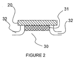
- Figure 2 represents a polymer element 20 provided with the means 30 to generate the external stress, that is in this case, thermal energy.
- the means 30 are made up of a temperature control element, for example, a heating element 31 placed below the polymer element.
- the heating element is made up for example with a thin layer of polycrystal silicon wherein a current is made to flow that is adapted to the generation of a quantity of thermal energy that allows the polymer to exceed its phase transition temperature to switch from one state to the other.
- the polymer element can then return to its initial state, its temperature having decreased by the simple diffusion of the heat.
- an additional cooling system can be provided such as for example a radiator or a Pelletier effect device.
- thermo-reversible polymers which are used in the present device, are organic polymers such as those described in Patent Application WO 91/15526. These are polymers that have a hydrophilic group and a hydrophobic group, the hydrophilic group being a water-soluble ionic polymerizable vinyl monomer, and the hydrophobic group comprising an acrylamide or methacrylamide monomer.
- a poly(N-alkylacrylamide) a modified glycol polyethylene or a polysilylamine will be chosen.
- a polymer will be used that switches from one state to the other very fast, for example poly(N-isopropylacrylamide).
- a hydrophilic/hydrophobic phase transition temperature Tg proper to the polymer Poly(N-isopropylacrylamide) has a temperature Tg of about 32°. When the polymer is at a temperature less than 32°, it is hydrophilic. When it is higher than 32°, it becomes hydrophobic.
- the hydrophilic/hydrophobic phase transition temperature of a polymer can be modified by different means. For example adding a surfactant to the fluid to be carried can increase the phase transition temperature. This technique is described in the publication, Langmuir, 1995, volume 11, No. 7, pages 2493-2495. For example the phase transition temperature Tg of poly(N-isopropylacrylamide) can be modified from 32°C to 90°C.
- Electrically conductive organic polymers can be chosen, for example polymethylethiophene, which under the action of an electric current as an external stress switches from the hydrophilic state to the hydrophobic state or vice-versa.
- the means to generate the external stress in this case are means to apply an electric current to the polymer element.
- the hydrophilic/hydrophobic state change causes the polymer's volume to vary.
- how to control the volume variations of polymers that can switch from a hydrophilic to a hydrophobic state is known. Therefore, known techniques such as those described in Polymer Communications, "Synthesis of fast response, temperature-sensitive poly(N-isopropylacrylamide) gel", can be used.
- the polymers used are thermo-reversible polymers.
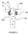
- Figures 3 and 4 represent a channel 40 filled with a fluid 10.
- means 20, 30 are provided for moving the fluid 10 along the internal wall of the channel 40, close to the end 40a of the channel.
- the moving means include a polymer element 20 whose hydrophilic or hydrophobic properties can be selected under the action of thermal energy.
- the polymer element 20 can be in a hydrophilic state 20a or hydrophobic state 20b.
- the said moving means also include means to control the temperature, which are the heating means 31 for the polymer element 20.
- the heating means 31 are the same as those described for Figure 2.
- the polymer element 20 is covered by the heating means.
- the polymer element can then be heated to exceed a threshold temperature, which is the polymer's phase transition temperature.
- the polymer element 20 is represented in its hydrophilic state 20a.
- the fluid 10 is uniformly distributed throughout the channel 40.
- Figure 4 represents the polymer element 20 in its hydrophobic state 20b.
- the fluid 10 found at the hydrophobic polymer element 20b tends to be repelled by this element, an empty volume 50 thus being created inside the channel 40.
- the volume of fluid that was found between the polymer element 20 and the end 40a of the channel is an independent volume of fluid that is moved out of the channel.
- the feeding means can be maintained under pressure by any means known to those skilled in the art.
- the fluid to be moved by the device according to the invention is a printing fluid, for example printing ink, or a thermopolymer which allows three-dimensional printing in stereolithographic processes.
- Figures 5A and 5B represent a portion of a fluid jet head 60 for printing on a support 800 which comprises a means of feeding 700 the printing fluid, a channel 400 for moving the fluid 100 outwards.
- the device for moving the fluid according to the invention is an ink jet head.
- the channel 400 ends in a nozzle 400a open to the outside.
- the periphery of the nozzle 400a is provided with a polymer element 200.
- the polymer element 200 can be in a hydrophilic state 200a or in a hydrophobic state 200b. Such an element is provided to create an ink drop 100, thus allowing the ink 100 to be ejected.
- the polymer element 200 is preferably a very thin layer.
- the means for controlling the temperature are heating means 310 such as those described above.
- the said means of heating 310 are provided below the polymer element 200.
- Figure 5A represents the portion of the ink jet head when the polymer element is in its hydrophilic state 200a.
- the ink As the means of feeding 700 the ink always being maintained under pressure to prevent the ink from returning into the feeding means 700, the inks tends to come and stay in contact with the polymer element 200a.
- the polymer element switches to its hydrophobic state 200b as is represented in Figure 5B, the ink tends to go away from the polymer element 200b. Since the means for feeding the ink is maintained under pressure, the ink cannot return to the feeding means 700 and an ink drop forms.
- the ink drop 100 can then be ejected by any means known to those skilled in the art. For example an electrostatic field can be applied as described in Patent Application WO 96/322284.
- the polymer element is provided not at the periphery of the nozzle but along the internal wall of the channel 400, close to the nozzle 400a.
- the polymer element is preferably ring-shaped.
- an element at the periphery can also be used to allow the ink to be ejected. For example, if the fluid is hydrophilic, the element will be a hydrophobic polymer element.
- Figure 6 represents another embodiment of the ink jet head 60 according to the invention.
- a first polymer element 200 is provided at the periphery of the nozzle 400a and a second polymer element 201 is provided along the internal wall of the channel 400.
- the polymer element 201 is preferably ring-shaped.
- Heating means 310 and 311 are provided to heat the polymer elements 200 and 201 respectively.
- the volume of the drop to be ejected can be determined.
- the polymer elements 200 and 201 are initially in a hydrophilic state. When a volume of ink required to form a drop is obtained, the polymer element 201 is heated and switches to its hydrophobic state. The volume of ink is moved out of the channel 400. Then the polymer element 200 is switched to its hydrophobic state in order to allow the ink drop to be ejected. Since the polymer element 201 is maintained in its hydrophobic state, the ink drop cannot return to the channel 400.
- heating means are provided to heat, not the polymer element directly, but the ink 100 in the means for feeding the ink 700.
- a polymer element 200 is provided at the periphery of the nozzle 400a.
- the materials of the external surface of the ink jet head are planned to be hydrophobic. The ink will therefore not tend to spread beyond the polymer element 200.
- the ink 100 is heated to a temperature T higher than the phase transition temperature Tg of the polymer element 200.
- Tg phase transition temperature
- the ink 100 leaves the nozzle 400a at the temperature T, it is in contact with the polymer element 200.
- the heat of the ink is transferred to the polymer element 200, which exceeds its phase transition temperature Tg.
- the polymer element 200 switches to its hydrophobic state 200b.
- the wetting angle of the ink 100 increases, therefore creating an ink drop 100.
- the ink drop 100 can then be ejected in the same way as described in the embodiment represented in Figure 5B.
- the heating means is not activated, the ink 100 has a temperature less than the phase transition temperature of the polymer element 200, which is therefore in its hydrophilic state 200a.
- the ink cannot form a drop at the surface of the ink jet head, and therefore there is no ejection.
- the pressure maintained in the feeding means can be decreased or canceled in order to return the ink into the feeding means.
- a ring-shaped polymer element 201 is advantageously provided inside the channel 400 so as to control the ejection of the ink 100.
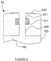
- Figure 8 represents this alternative embodiment.
- Heating means 311 such as those described in Figure 2 are provided to heat the polymer element 201.
- the polymer element 201 cover the whole surface area of the heating means 311, so that the whole surface of the polymer element 201 changes state.
- the phase transition temperature Tg' of the polymers used in the polymer element 201 must be higher than the phase transition temperature Tg of the polymers used in the polymer element 200 and higher than the temperature T of the ink.
- the polymer element 201 is maintained in its hydrophobic state by raising it to a temperature higher than Tg' using the heating means 311.
- the ink 100 present in the channel 400 is no longer able to run out to the surface of the ink jet head, making all ejection impossible.
- the polymer element 201 is maintained in its hydrophilic state by not activating the heating means 311. Therefore the ink 100 can run freely out to the surface of the ink jet head.
- the ink temperature T is higher than the phase transition temperature Tg of the polymer element 200, it follows that on contact with the ink, this polymer element 200 will switch from the hydrophilic state to the hydrophobic state and therefore allow an ink drop to form on the surface of the head.
- the polymer element 201 can then be raised to its hydrophobic state by activating the heating means 311 which stops the flow of ink in the channel 400 and therefore allows the volume of ink to be ejected to be accurately selected.
- the heating means 311 which stops the flow of ink in the channel 400 and therefore allows the volume of ink to be ejected to be accurately selected.
- the polymer element 200 which is no longer in contact with the heated ink, returns to its hydrophilic state.
- the heating means 311 is deactivated, which allows the polymer element 201 to return to its hydrophilic state and therefore allows the ink 100 to run freely in the channel 400 out to the surface of the ink jet head.
Landscapes
- Particle Formation And Scattering Control In Inkjet Printers (AREA)
- Ink Jet (AREA)
Claims (24)
- Dispositif comprenant des moyens de déplacement d'un fluide (10) hors d'un canal, caractérisé en ce que les moyens de déplacement du fluide (10) comprennent un polymère dont les propriétés hydrophiles ou hydrophobes peuvent être choisies sous l'action d'une contrainte extérieure.
- Dispositif selon la revendication 1, dans lequel les moyens de déplacement du fluide (10) comprennent au moins un élément de polymère (20) dont les propriétés hydrophiles ou hydrophobes peuvent être choisies sous l'action d'une contrainte extérieure, et des moyens (30) permettant de générer ladite contrainte extérieure.
- Dispositif selon la revendication 2, dans lequel l'élément de polymère (20) est prévu le long de la paroi interne du canal (40).
- Dispositif selon la revendication 3, caractérisé en ce que le polymère, dont les propriétés hydrophiles ou hydrophobes peuvent être choisies sous l'action d'une contrainte extérieure, est un polymère thermoréversible.
- Dispositif selon la revendication 4, dans lequel les moyens (30) permettant de générer ladite contrainte extérieure sont des moyens de contrôle de la température.
- Dispositif selon la revendication 5, dans lequel les moyens de contrôle de la température comprennent une résistance (31) en contact avec l'élément de polymère (20), ladite résistance étant alimentée par un circuit électrique.
- Dispositif selon la revendication 3, dans lequel le polymère, dont les propriétés hydrophiles ou hydrophobes peuvent être choisies sous l'action d'une contrainte extérieure, est un polymère organique conducteur de l'électricité.
- Dispositif selon la revendication 7, dans lequel les moyens (30) permettant de générer ladite contrainte extérieure sont des moyens permettant d'appliquer un courant électrique.
- Dispositif selon l'une quelconque des revendications précédentes, caractérisé en ce qu'il comprend en outre :1) au moins un moyen d'alimentation en fluide ;2) au moins un récepteur de fluide.
- Tête d'impression à jet de fluide (60) comprenant :a) au moins un moyen d'alimentation (700) en fluide d'impression ;b) au moins un canal (400) terminé par une buse (400a) ouverte sur l'extérieur ;c) des moyens de déplacement du fluide d'impression (100), caractérisé en ce qued) les moyens de déplacement du fluide d'impression (100) comprennent un polymère dont les propriétés hydrophiles ou hydrophobes peuvent être choisies sous l'action d'une contrainte extérieure.
- Tête d'impression à jet de fluide (60) selon la revendication 10, dans laquelle lesdits moyens de déplacement du fluide d'impression (100) comprennent, d'une part, au moins un élément de polymère (200) dont les propriétés hydrophiles ou hydrophobes peuvent être choisies sous l'action de la contrainte extérieure, et d'autre part, des moyens permettant de générer ladite contrainte.
- Tête d'impression à jet de fluide (60) selon la revendication 11, dans laquelle l'élément de polymère est placé soit à la périphérie de l'orifice de la buse (400a), soit le long de la paroi interne du canal (400), soit à la périphérie de l'orifice de la buse (400a) et le long de la paroi interne du canal (400).
- Tête à jet de fluide selon la revendication 12, dans laquelle lorsque l'élément de polymère est prévu le long de la paroi interne du canal (400), un élément est prévu à la périphérie de la buse (400a) dans un état facilitant l'éjection du fluide (100).
- Tête d'impression à jet de fluide (60) selon la revendication 12, dans laquelle l'élément de polymère (201) prévu le long de la paroi interne du canal (400) est placé à proximité de l'orifice de la buse (400a).
- Tête d'impression à jet de fluide (60) selon l'une quelconque des revendications 11 à 15, dans laquelle le polymère dont les propriétés hydrophiles ou hydrophobes peuvent être choisies sous l'action d'une contrainte extérieure est un polymère thermoréversible.
- Tête d'impression à jet de fluide (60) selon la revendication 15, dans laquelle les moyens permettant de générer ladite contrainte extérieure sont des moyens de contrôle de la température.
- Tête d'impression à jet de fluide (60) selon la revendication 16, dans laquelle les moyens de contrôle de la température comprennent des résistances alimentées par un circuit électrique, chaque élément de polymère étant en contact avec une résistance.
- Tête d'impression à jet de fluide (60) selon la revendication 16, dans laquelle les moyens de contrôle de la température sont prévus pour contrôler la température du fluide d'impression (100) dans le moyen d'alimentation (700) en fluide d'impression.
- Tête d'impression à jet de fluide (60) selon la revendication 18, dans laquelle lorsqu'un élément de polymère est prévu à la périphérie de l'orifice de la buse (400a) et le long de la paroi interne du canal (400), les moyens de contrôle de la température comprennent une résistance (311) en contact avec l'élément de polymère prévu le long de la paroi interne du canal (400).
- Tête d'impression à jet de fluide (60) selon l'une quelconque des revendications 10 à 14, dans laquelle le polymère est un polymère organique conducteur de l'électricité.
- Tête d'impression à jet de fluide (60) selon la revendication 20, dans laquelle les moyens permettant de générer la contrainte extérieure sont des moyens permettant d'appliquer un courant électrique.
- Tête d'impression à jet de fluide selon l'une quelconque des revendications 10 à 21, dans laquelle le fluide est l'encre.
- Utilisation d'un polymère dont les propriétés hydrophiles ou hydrophobes peuvent être choisies sous l'action d'une contrainte extérieure dans une tête d'impression à jet de fluide telle que revendiquée dans l'une quelconque des revendications 10 à 22.
- Utilisation d'un polymère dont les propriétés hydrophiles ou hydrophobes peuvent être choisies sous l'action d'une contrainte extérieure dans un dispositif de déplacement d'un fluide tel que revendiqué dans l'une quelconque des revendications 1 à 9.
Applications Claiming Priority (2)
| Application Number | Priority Date | Filing Date | Title |
|---|---|---|---|
| FR9803011A FR2775625B1 (fr) | 1998-03-06 | 1998-03-06 | Dispositif de deplacement d'un fluide |
| FR9803011 | 1998-03-06 |
Publications (2)
| Publication Number | Publication Date |
|---|---|
| EP0940255A1 EP0940255A1 (fr) | 1999-09-08 |
| EP0940255B1 true EP0940255B1 (fr) | 2004-07-07 |
Family
ID=9523940
Family Applications (1)
| Application Number | Title | Priority Date | Filing Date |
|---|---|---|---|
| EP19990420052 Expired - Lifetime EP0940255B1 (fr) | 1998-03-06 | 1999-03-01 | Dispositif de déplacement d'un fluide |
Country Status (3)
| Country | Link |
|---|---|
| EP (1) | EP0940255B1 (fr) |
| DE (1) | DE69918476T2 (fr) |
| FR (1) | FR2775625B1 (fr) |
Families Citing this family (4)
| Publication number | Priority date | Publication date | Assignee | Title |
|---|---|---|---|---|
| FR2779667B1 (fr) | 1998-06-12 | 2001-06-29 | Eastman Kodak Co | Dispositif pour gerer le deplacement de fluides |
| JP4595369B2 (ja) * | 2004-03-31 | 2010-12-08 | ブラザー工業株式会社 | 液体移送ヘッド及びこれを備えた液体移送装置 |
| US7413287B2 (en) | 2005-06-30 | 2008-08-19 | Brother Kogyo Kabushiki Kaisha | Liquid discharging apparatus |
| JP4774977B2 (ja) * | 2005-12-19 | 2011-09-21 | ブラザー工業株式会社 | 液体移送装置 |
Family Cites Families (13)
| Publication number | Priority date | Publication date | Assignee | Title |
|---|---|---|---|---|
| JPS5845352B2 (ja) * | 1977-06-13 | 1983-10-08 | 株式会社リコー | 記録方法 |
| US4166277A (en) * | 1977-10-25 | 1979-08-28 | Northern Telecom Limited | Electrostatic ink ejection printing head |
| US4275290A (en) * | 1978-05-08 | 1981-06-23 | Northern Telecom Limited | Thermally activated liquid ink printing |
| US4396925A (en) * | 1980-09-18 | 1983-08-02 | Matsushita Electric Industrial Co., Ltd. | Electroosmotic ink printer |
| JPS60110709A (ja) * | 1983-11-21 | 1985-06-17 | Agency Of Ind Science & Technol | 側鎖にν−シクロプロピルアクリルアミド基をもつ親水性−疎水性熱可逆型材料及びその製造法 |
| US5278126A (en) * | 1989-03-31 | 1994-01-11 | Ricoh Company, Ltd. | Recording process and apparatus and recording medium in the same |
| WO1991015526A2 (fr) | 1990-04-02 | 1991-10-17 | Eastman Kodak Company | Polyacrylamides thermoreversibles thermoepaississants |
| JPH0421844A (ja) * | 1990-05-16 | 1992-01-24 | Matsushita Electric Ind Co Ltd | 画像形成装置 |
| JPH05104737A (ja) * | 1991-10-17 | 1993-04-27 | Minolta Camera Co Ltd | インクジエツト記録装置 |
| JPH08216368A (ja) * | 1995-02-14 | 1996-08-27 | Hitachi Ltd | 画像形成装置 |
| JP3666046B2 (ja) * | 1995-03-02 | 2005-06-29 | 松下電器産業株式会社 | 画像形成方法 |
| EP0771272A1 (fr) | 1995-04-12 | 1997-05-07 | Eastman Kodak Company | Tetes d'impression monolithiques et leurs procedes de fabrication |
| EP0796902A3 (fr) * | 1996-03-22 | 1998-11-25 | Eastman Kodak Company | Composition d'encre avec copolymères blocs PEO/PPO |
-
1998
- 1998-03-06 FR FR9803011A patent/FR2775625B1/fr not_active Expired - Fee Related
-
1999
- 1999-03-01 EP EP19990420052 patent/EP0940255B1/fr not_active Expired - Lifetime
- 1999-03-01 DE DE69918476T patent/DE69918476T2/de not_active Expired - Lifetime
Also Published As
| Publication number | Publication date |
|---|---|
| DE69918476T2 (de) | 2005-08-18 |
| EP0940255A1 (fr) | 1999-09-08 |
| FR2775625B1 (fr) | 2000-05-05 |
| FR2775625A1 (fr) | 1999-09-10 |
| DE69918476D1 (de) | 2004-08-12 |
Similar Documents
| Publication | Publication Date | Title |
|---|---|---|
| EP0600712B1 (fr) | Méthode et appareil pour l'impression par transfert d'encre | |
| US5745128A (en) | Method and apparatus for ink transfer printing | |
| EP0864423B1 (fr) | Dispositif pour l'impression par transfert d'encre avec règlage du volume de goutte et procédé pour sa mise en oeuvre | |
| US20010020967A1 (en) | Variable drop mass inkjet drop generator | |
| KR920010635B1 (ko) | 열용융 잉크젯트 인쇄시스템 | |
| EP1080904B1 (fr) | Tête d'impression générant des gouttes à haute densité | |
| US6113221A (en) | Method and apparatus for ink chamber evacuation | |
| US20010008411A1 (en) | Variable drop mass inkjet drop generator | |
| JP2832576B2 (ja) | 温度保持装置及び方法 | |
| CA2174181C (fr) | Tete d'ejection de liquide; dispositif d'ejection de liquide et methode d'ejection de liquide | |
| KR100504973B1 (ko) | 방울크기변경을위한잉크젯프린트헤드 | |
| KR100783976B1 (ko) | 잉크젯 프린팅 장치, 잉크 도트를 매체상에 부착하는 방법및 잉크젯 프린팅 장치의 제조 방법 | |
| US5481280A (en) | Color ink transfer printing | |
| EP0940255B1 (fr) | Dispositif de déplacement d'un fluide | |
| US6435665B2 (en) | Device for controlling fluid movement | |
| US6498615B1 (en) | Ink printing with variable drop volume separation | |
| EP1112847A2 (fr) | Système d'impression continue à jet d'encre muni d'un déflecteur avec encoche | |
| US6406131B2 (en) | Device for moving a fluid | |
| US6318847B1 (en) | Segmented heater resistor for producing a variable ink drop volume in an inkjet drop generator | |
| JPH01247168A (ja) | インクジェットヘッド | |
| EP0976557B1 (fr) | Dispositif d'impression utilisant des polymères hydrophiles/hydrophobes | |
| US6711806B2 (en) | Method of manufacturing a thermal fluid jetting apparatus | |
| JP2004345323A (ja) | 液滴噴射方法及び装置 | |
| JPS63139749A (ja) | インクジエツト記録ヘツド | |
| EP0963842B1 (fr) | Dispositif pour gérer le déplacement de fluides |
Legal Events
| Date | Code | Title | Description |
|---|---|---|---|
| PUAI | Public reference made under article 153(3) epc to a published international application that has entered the european phase |
Free format text: ORIGINAL CODE: 0009012 |
|
| AK | Designated contracting states |
Kind code of ref document: A1 Designated state(s): DE FR GB |
|
| AX | Request for extension of the european patent |
Free format text: AL;LT;LV;MK;RO;SI |
|
| 17P | Request for examination filed |
Effective date: 20000207 |
|
| AKX | Designation fees paid |
Free format text: DE FR GB |
|
| 17Q | First examination report despatched |
Effective date: 20030404 |
|
| GRAP | Despatch of communication of intention to grant a patent |
Free format text: ORIGINAL CODE: EPIDOSNIGR1 |
|
| GRAS | Grant fee paid |
Free format text: ORIGINAL CODE: EPIDOSNIGR3 |
|
| GRAA | (expected) grant |
Free format text: ORIGINAL CODE: 0009210 |
|
| AK | Designated contracting states |
Kind code of ref document: B1 Designated state(s): DE FR GB |
|
| REG | Reference to a national code |
Ref country code: GB Ref legal event code: FG4D |
|
| REF | Corresponds to: |
Ref document number: 69918476 Country of ref document: DE Date of ref document: 20040812 Kind code of ref document: P |
|
| ET | Fr: translation filed | ||
| PLBE | No opposition filed within time limit |
Free format text: ORIGINAL CODE: 0009261 |
|
| STAA | Information on the status of an ep patent application or granted ep patent |
Free format text: STATUS: NO OPPOSITION FILED WITHIN TIME LIMIT |
|
| 26N | No opposition filed |
Effective date: 20050408 |
|
| PGFP | Annual fee paid to national office [announced via postgrant information from national office to epo] |
Ref country code: FR Payment date: 20120328 Year of fee payment: 14 |
|
| PGFP | Annual fee paid to national office [announced via postgrant information from national office to epo] |
Ref country code: GB Payment date: 20120227 Year of fee payment: 14 |
|
| PGFP | Annual fee paid to national office [announced via postgrant information from national office to epo] |
Ref country code: DE Payment date: 20130328 Year of fee payment: 15 |
|
| GBPC | Gb: european patent ceased through non-payment of renewal fee |
Effective date: 20130301 |
|
| REG | Reference to a national code |
Ref country code: FR Ref legal event code: ST Effective date: 20131129 |
|
| PG25 | Lapsed in a contracting state [announced via postgrant information from national office to epo] |
Ref country code: FR Free format text: LAPSE BECAUSE OF NON-PAYMENT OF DUE FEES Effective date: 20130402 Ref country code: GB Free format text: LAPSE BECAUSE OF NON-PAYMENT OF DUE FEES Effective date: 20130301 |
|
| REG | Reference to a national code |
Ref country code: DE Ref legal event code: R119 Ref document number: 69918476 Country of ref document: DE |
|
| REG | Reference to a national code |
Ref country code: DE Ref legal event code: R119 Ref document number: 69918476 Country of ref document: DE Effective date: 20141001 |
|
| PG25 | Lapsed in a contracting state [announced via postgrant information from national office to epo] |
Ref country code: DE Free format text: LAPSE BECAUSE OF NON-PAYMENT OF DUE FEES Effective date: 20141001 |