EP0940523A2 - Elément de fixation pour la fixation de plaques à isolation thermique à une sous-construction, avec contrÔle de l'assemblage - Google Patents
Elément de fixation pour la fixation de plaques à isolation thermique à une sous-construction, avec contrÔle de l'assemblage Download PDFInfo
- Publication number
- EP0940523A2 EP0940523A2 EP99101761A EP99101761A EP0940523A2 EP 0940523 A2 EP0940523 A2 EP 0940523A2 EP 99101761 A EP99101761 A EP 99101761A EP 99101761 A EP99101761 A EP 99101761A EP 0940523 A2 EP0940523 A2 EP 0940523A2
- Authority
- EP
- European Patent Office
- Prior art keywords
- expansion
- fastening
- shaft part
- holding element
- fastening element
- Prior art date
- Legal status (The legal status is an assumption and is not a legal conclusion. Google has not performed a legal analysis and makes no representation as to the accuracy of the status listed.)
- Granted
Links
Images


Classifications
-
- E—FIXED CONSTRUCTIONS
- E04—BUILDING
- E04B—GENERAL BUILDING CONSTRUCTIONS; WALLS, e.g. PARTITIONS; ROOFS; FLOORS; CEILINGS; INSULATION OR OTHER PROTECTION OF BUILDINGS
- E04B1/00—Constructions in general; Structures which are not restricted either to walls, e.g. partitions, or floors or ceilings or roofs
- E04B1/62—Insulation or other protection; Elements or use of specified material therefor
- E04B1/74—Heat, sound or noise insulation, absorption, or reflection; Other building methods affording favourable thermal or acoustical conditions, e.g. accumulating of heat within walls
- E04B1/76—Heat, sound or noise insulation, absorption, or reflection; Other building methods affording favourable thermal or acoustical conditions, e.g. accumulating of heat within walls specifically with respect to heat only
- E04B1/762—Exterior insulation of exterior walls
- E04B1/7629—Details of the mechanical connection of the insulation to the wall
- E04B1/7633—Dowels with enlarged insulation retaining head
-
- E—FIXED CONSTRUCTIONS
- E04—BUILDING
- E04F—FINISHING WORK ON BUILDINGS, e.g. STAIRS, FLOORS
- E04F13/00—Coverings or linings, e.g. for walls or ceilings
- E04F13/07—Coverings or linings, e.g. for walls or ceilings composed of covering or lining elements; Sub-structures therefor; Fastening means therefor
- E04F13/08—Coverings or linings, e.g. for walls or ceilings composed of covering or lining elements; Sub-structures therefor; Fastening means therefor composed of a plurality of similar covering or lining elements
- E04F13/0801—Separate fastening elements
- E04F13/0832—Separate fastening elements without load-supporting elongated furring elements between wall and covering elements
- E04F13/0833—Separate fastening elements without load-supporting elongated furring elements between wall and covering elements not adjustable
- E04F13/0835—Separate fastening elements without load-supporting elongated furring elements between wall and covering elements not adjustable the fastening elements extending into the back side of the covering elements
Definitions
- the invention relates to a fastener for fastening heat insulating panels on a substructure with a holding element and an expansion element to be introduced into this.
- the holding element has one Pressure plate at its upper end, a shaft part that attaches to the pressure plate connects and a spreading area in a lower area. That in that Retaining element to be introduced is designed such that it is up to a lower end position in the holding element can be inserted into the holding element, so that it is the spreading area of the holding element in the inserted state apart.
- Fastening elements for fastening heat-insulating plates must be attached to the adapted to various application-specific thicknesses of these insulation boards to ensure secure anchoring in the substructure guarantee.
- a fastening element is presented in DE-OS 196 51 046, in which the length of the holding element, as well as the length of the The screw to be inserted is adapted to the thickness of the insulation board.
- a similar fastener is also from DE-OS 196 48 823 provided, with an impact socket instead of a screw according to the length to be selected.
- the object of the present invention is a fastener To provide, in which the expansion element length regardless of the thickness of the fixing insulation board can be kept and in which the proper insertion of the expansion element in the holding element is simple and safe to control.
- a fastening element for fastening heat-insulating Slabs on a substructure with a holding element and a Spreading element provided, the holding element having a pressure plate on its upper end, a shaft part that adjoins the pressure plate downwards, and has a spreading area in its lower area, and wherein the Spreading element is designed such that it is up to a lower end position in the Retaining element can be inserted into the holding element, so that it is inserted in the State pushes apart the expansion area of the holding element.
- a position rod is attached to the expansion element in such a way that it is exactly when the expansion element up to the lower end position in the Holding element is inserted is completely sunk in the holding element.
- the expansion element length must be in a fastener according to the invention can no longer be varied with the thickness of the insulation panels, but can be kept constant. It is sufficient, on the one hand, the length of the holding element between its upper end, d. H. the pressure plate, and the lower one End position, and on the other hand to vary the length of the position bar.
- the expansion element itself can be used unchanged for all insulation board thicknesses become.
- the fastening element according to the invention too violent by setting up a position staff Introducing the expansion element into the holding element to ensure the fixed Anchoring the same prevented.
- the clearly visible complete immersion the position rod in the holding element is namely a sufficient sign for proper assembly.
- the shaft part of the holding element is made of composed of at least two parts, namely an upper and one lower part. This makes it possible with the respective adaptation to the thickness of the to be fastened, only another upper part of the shaft part to use. The lower part of the shaft part, which contains the expansion area, can then be used regardless of the respective insulation board thickness. This results in clear rationalization advantages.
- the contact surface between the lower and the upper part of the shaft part for exact mounting of the lower part in the upper part Provide material surveys. It can be ribs and / or raised Trade points. Other structurally selected structures are also possible.
- the lower end position is a stop, which is formed by the upper end of the lower part of the shaft part.
- the upper and the lower part of the shaft part are over one Snap mechanism connected together.
- the lower one shows Part at its end facing the pressure plate an angular head.
- the upper part then has, for example, two resilient tongues for receiving of the head of the lower part can spring outwards.
- the position rod preferably has a clamping element at its lower end on to take the position rod with the expansion element when To allow insertion into the holding element.
- the clamping element it can are, for example, a kind of clip with semicircular arms that grips the expanding element in a clamped manner.
- the clamping mechanism is preferred positive, so that the position rod is not opposite the expansion element is movable.
- the expansion element has, for example, at the point where the Position rod to be clamped a corresponding recess for Inclusion of the clamping element of the position rod. It can be for example, around a radial circumference, the shape of the arms of the act clamp-like clamping element adapted recess, the arms of the clamp-like clamping element.
- a non-positive Clamping effect between the clamping element and the expansion element is also conceivable.
- the one then given at least downwards relative to the expansion element Movability of the position bar opens the possibility for the Fitter to sink the position rod in the shaft part without the expansion element to have sunk properly.
- the advantage of overwinding or excessive impact of the expansion element can be avoided remains received however.
- the position bar has its upper end has a flexible and / or swiveling cover that the Shaft part of the holding element closes when the expansion element is the lower one Has reached the end position.
- this lid can be in the Uniklappen holding element so that it is flat on or in the insertion opening Pressure plate comes to rest and closes it.
- the Pressure plate has a corresponding recess for receiving the cover intended.
- the cover provides protection against plastering penetrating plaster.
- one of the Position rod independent cap for closing the pressure plate over its Insertion opening may be provided.
- this cap can be chosen in this way be that it is articulated on one side with the pressure plate and after Insert the spreading element folded by hand and on top of the Pressure plate is pressed. To ensure a secure hold of the cap the cap is palpated with the pressure plate. This can be done, for example be realized that a projection is provided on the edge of the cap, the is pressed into a corresponding recess in the pressure plate.
- the Cap preferably has the shape of a flat round plate, according to its Press down on the pressure plate to lie largely flat on the top comes and is not a hindrance when plastering.
- a longitudinal groove in which the position rod when inserting the expansion element can be performed is Appropriately located on the inside of the upper part of the Shaft part a longitudinal groove in which the position rod when inserting the expansion element can be performed. This can prevent that in the event that the expansion element is a screw, the position rod for Screwing in the same with a drill and thereby is damaged.
- the expansion element preferably has a metallic base body and one Head made of plastic, with the end facing the head of the metallic Base body is provided with a plastic coating. Based on these The arrangement allows the formation of a cold-thermal bridge through the metallic base body is favored, effectively suppress. Preferably closes the plastic head with its underside or the subsequent one Plastic coating the hole at the top of the lower part of the shaft part of the holding element. The additional sheathing of part of the Expanding element shaft following the expansion element head grants a additional radial seal in the lower part of the shaft part of the Holding element.
- the expansion element can be used to drive in or Be screwed in.
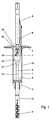
- Fig. 1 shows a fastener according to the invention during insertion an expansion element 5 according to the invention in a holding element according to the invention 1 with a pressure plate 2, a shaft part 3, which has an upper part 10 and has a lower part 11 and with an expansion area 4.
- the expansion element 5 is a screw with an inventive Spreading element head.
- the plastic head 16 of the Spreading element 5 has a recess 19 for receiving an assembly bit, in this example of a screwdriver.
- A is also shown Position rod 6 according to the invention with a flexible and pivotable lid 8, which is bent up during the driving process and on which Mounting bit rests resiliently.
- the plastic head 16 has a radial circumferential Recess 18 for the positive reception of the clamping element 7 of the Position rod 6 on.
- a plastic head 16 is included at the bottom Plastic coated area 17. This area is used for sealing inside the lower part 11 of the shaft part 3.
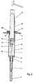
- Fig.2 shows another fastener according to the invention during the Introducing another expansion element 5 according to the invention into another Holding element 1 according to the invention, wherein the holding element 1 is a pressure plate 2 and has an adjoining shaft part 3.
- the shaft part 3 has an upper part 10 and a lower part 11.
- the expansion element is concerned a firing pin.
- the Plastic head no recess for receiving an assembly bit.
- the surface of the plastic head shows a curvature such that the firing pin, with the help of which the firing pin is driven in, if possible has a large contact area and thus guarantees maximum power transmission is.
- a wedge 22 is used here.
- Fig. 3 shows an inventive fastener after complete Introducing the expansion element 5 into the holding element 1.
- the metallic Base body 15 of the expansion element 5 spreads the expansion area 4 of the Holding element 1, whereby anchoring in the substructure is achieved becomes.
- the position rod 6 is completely sunk in the holding element 1 here.
- Of the Cover 8 of the position rod is just in the corresponding recess 13 folded into the pressure plate 2.
- FIG. 5a shows a position rod 6 according to the invention with one on one End located flexible and pivotable lid 8 and with a opposite end of the clamping element 7 arranged at right angles
- Lid is flexible to the extent that it moves in without any force Direction can be bent against the clamping element. It is the other way round but also possible to pivot the lid so that it is at a right angle includes with the position rod and thus the shaft part of the holding element closes when the expansion element has reached the lower end position.
- the Clamping element 7, which is arranged at right angles at the lower end of the position rod can be seen in a top view in FIG. 5b. It has the shape of a Ring cutout.
- the clamping arms thus formed are intended to be the expansion element embrace and clamp.
- Fig. 6 shows the pressure plate 2 from the side (Fig. 6a) and in top view (Fig. 6b). Shown is the one running along the upper part 10 of the shaft part 3 Projection 12, with the help of which the position rod 6 is prevented with the screw to be screwed in.
- the projection 12 thus has the Function of a stop for the position rod 6.
- An embodiment of this The lead is even clearer in the enlargement of the cutout (FIG. 6c) detect.
- Fig. 6a are on the inside of the lower part 11 of the Shaft part 3 facing end of the upper part 10 of the shaft part 3 resilient Tongues 21 shown with wedge-like projections 20, with the help of which the lower and the upper region of the shaft part 3 can be connected to one another.
- Fig. 6a are on the inside of the lower part 11 of the Shaft part 3 facing end of the upper part 10 of the shaft part 3 resilient Tongues 21 shown with wedge-like projections 20, with the help of which the lower and the upper region of the shaft part 3 can be connected to one another.
- FIG. 6d shows the element according to Fig. 6a rotated by 90 °.
- the size of the recess 13 is chosen so that the lid 8 of the Position rod after pressing into the recess 13 firmly in the pressure plate is engaged.
- Granting flexibility to the size of the recess 13 is somewhat spaced apart a recess 14 is provided in the recess 13.
- the latter is in the enlargement can be seen even more clearly according to FIG. 6e.
- the two tongues 21, which are used to anchor the lower part 11 serve the upper part 10 and have the projections 20 (Fig. 6a).
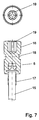
- FIG. 7 shows an expansion element head according to the invention.
- the plastic head 16 of the expansion element shown on the metallic Head of the metallic base body 15 of the expansion element is applied and this extended upwards.
- This plastic head 16 has a radial circumferential recess 18 for receiving the clamping element of the Position bar on.
- a plastic head 16 is included at the bottom Plastic coated area 17. This area 17 is used for sealing of the expansion element 5 against the lower region of the shaft part 3 of the Holding element 1. The spreading element 5 is therefore in the inserted state Corrosion protected.
- the plastic head 16 has a recess at the top 19 to accommodate the assembly bit, which is even clearer in the plan view is shown.
Landscapes
- Engineering & Computer Science (AREA)
- Architecture (AREA)
- Civil Engineering (AREA)
- Structural Engineering (AREA)
- Physics & Mathematics (AREA)
- Electromagnetism (AREA)
- Acoustics & Sound (AREA)
- Connection Of Plates (AREA)
- Clamps And Clips (AREA)
- Building Environments (AREA)
- Joining Of Building Structures In Genera (AREA)
- Mounting Of Printed Circuit Boards And The Like (AREA)
- Insertion Pins And Rivets (AREA)
- Inorganic Insulating Materials (AREA)
- Insulation, Fastening Of Motor, Generator Windings (AREA)
Applications Claiming Priority (2)
| Application Number | Priority Date | Filing Date | Title |
|---|---|---|---|
| DE19808927A DE19808927C1 (de) | 1998-03-03 | 1998-03-03 | Befestigungselement für die Befestigung von wärmeisolierenden Platten an einer Unterkonstruktion mit Montagekontrolle |
| DE19808927 | 1998-03-03 |
Publications (3)
| Publication Number | Publication Date |
|---|---|
| EP0940523A2 true EP0940523A2 (fr) | 1999-09-08 |
| EP0940523A3 EP0940523A3 (fr) | 2000-01-05 |
| EP0940523B1 EP0940523B1 (fr) | 2003-10-29 |
Family
ID=7859500
Family Applications (1)
| Application Number | Title | Priority Date | Filing Date |
|---|---|---|---|
| EP99101761A Expired - Lifetime EP0940523B1 (fr) | 1998-03-03 | 1999-02-11 | Elément de fixation pour la fixation de plaques à isolation thermique à une sous-construction, avec contrôle de l'assemblage |
Country Status (6)
| Country | Link |
|---|---|
| EP (1) | EP0940523B1 (fr) |
| AT (1) | ATE253160T1 (fr) |
| CZ (1) | CZ69699A3 (fr) |
| DE (2) | DE19808927C1 (fr) |
| HU (1) | HUP9900195A3 (fr) |
| PL (1) | PL331685A1 (fr) |
Families Citing this family (3)
| Publication number | Priority date | Publication date | Assignee | Title |
|---|---|---|---|---|
| DE20218422U1 (de) * | 2002-11-28 | 2004-04-08 | Fischerwerke Artur Fischer Gmbh & Co. Kg | Dämmstoffhalter |
| DE102006037025A1 (de) * | 2006-08-08 | 2008-02-14 | Ejot Baubefestigungen Gmbh | Befestigungssystem aus Dübel und Kunststoffnagel sowie Verfahren zur Montage von Dämmstoffplatten |
| CN106436933B (zh) * | 2016-11-01 | 2018-12-28 | 重庆方浩建筑保温材料有限公司万盛分公司 | 一种外顶式保温板固定连接装置 |
Citations (2)
| Publication number | Priority date | Publication date | Assignee | Title |
|---|---|---|---|---|
| DE19648823A1 (de) | 1996-11-26 | 1998-05-28 | Hardo Befestigungen Gmbh | Dämmstoffhalter |
| DE19651046A1 (de) | 1996-12-09 | 1998-06-10 | Hardo Befestigungen Gmbh | Dämmstoffhalter |
Family Cites Families (6)
| Publication number | Priority date | Publication date | Assignee | Title |
|---|---|---|---|---|
| EP0286706A1 (fr) * | 1987-04-15 | 1988-10-19 | GAPA-Werk Papenberg & Garz (GmbH & Co.) | Cheville |
| DE8904281U1 (de) * | 1989-04-06 | 1989-07-06 | Ejot Adolf Böhl GmbH & Co KG, 5920 Bad Berleburg | Vorrichtung zur Befestigung von Isolierstoffmatten an Bauwerkswänden |
| DE9410723U1 (de) * | 1994-07-02 | 1994-12-22 | Harald Zahn GmbH, 69168 Wiesloch | Trittsicheres Befestigungselement für Dämm- und Dichtungsmaterial auf Flachdächern |
| DE19504984A1 (de) * | 1995-02-15 | 1996-08-22 | Hilti Ag | Befestigungselement für Isolationsmaterialien |
| DE29506103U1 (de) * | 1995-04-07 | 1995-06-01 | Berner GmbH, 74653 Künzelsau | Dämmplattenhalter und Setzgerät dafür |
| DE19536171A1 (de) * | 1995-09-28 | 1997-04-03 | Ejot Kunststofftech Gmbh | Befestigungselement für die Befestigung von wärmeisolierenden Materialien |
-
1998
- 1998-03-03 DE DE19808927A patent/DE19808927C1/de not_active Expired - Fee Related
-
1999
- 1999-01-27 HU HU9900195A patent/HUP9900195A3/hu unknown
- 1999-02-11 DE DE59907491T patent/DE59907491D1/de not_active Expired - Lifetime
- 1999-02-11 EP EP99101761A patent/EP0940523B1/fr not_active Expired - Lifetime
- 1999-02-11 AT AT99101761T patent/ATE253160T1/de not_active IP Right Cessation
- 1999-03-01 CZ CZ99696A patent/CZ69699A3/cs unknown
- 1999-03-01 PL PL99331685A patent/PL331685A1/xx not_active IP Right Cessation
Patent Citations (2)
| Publication number | Priority date | Publication date | Assignee | Title |
|---|---|---|---|---|
| DE19648823A1 (de) | 1996-11-26 | 1998-05-28 | Hardo Befestigungen Gmbh | Dämmstoffhalter |
| DE19651046A1 (de) | 1996-12-09 | 1998-06-10 | Hardo Befestigungen Gmbh | Dämmstoffhalter |
Also Published As
| Publication number | Publication date |
|---|---|
| DE59907491D1 (de) | 2003-12-04 |
| EP0940523A3 (fr) | 2000-01-05 |
| HUP9900195A3 (en) | 2000-02-28 |
| HU9900195D0 (en) | 1999-03-29 |
| CZ69699A3 (cs) | 1999-10-13 |
| EP0940523B1 (fr) | 2003-10-29 |
| ATE253160T1 (de) | 2003-11-15 |
| DE19808927C1 (de) | 1999-07-08 |
| PL331685A1 (en) | 1999-09-13 |
| HUP9900195A2 (hu) | 1999-12-28 |
Similar Documents
| Publication | Publication Date | Title |
|---|---|---|
| DE69924602T2 (de) | Verglasungssystem | |
| DE2660131C2 (de) | Befestigungselement | |
| DE3045986C2 (de) | Befestigungselement für die Befestigung von wärmeisolierenden Platten | |
| EP0765979A1 (fr) | Elément de fixation pour la fixation de matériaux isolants | |
| EP0846878B1 (fr) | Fixation pour matériau isolant | |
| DE19912474C2 (de) | Befestigungsanordnung für die Anbringung eines Bauteils an einer C-förmigen Halteschiene | |
| EP0019782A2 (fr) | Cheville métallique creuse | |
| EP0504572B1 (fr) | Elément de fixation pour la fixation de plaques à isolation thermique | |
| EP2148098A2 (fr) | Elément d'ancrage en forme de plaque annulaire | |
| DE4006707C2 (de) | Vorreiberverschluß | |
| DE102016121074B3 (de) | Sammelschienenhalter und eine entsprechende Anordnung | |
| DE202012004845U1 (de) | Verbindungsanordnung mit einem Zwischenelement | |
| EP0940523B1 (fr) | Elément de fixation pour la fixation de plaques à isolation thermique à une sous-construction, avec contrôle de l'assemblage | |
| EP3425155B1 (fr) | Dispositif de protection anti-pince doigt pour une porte | |
| DE20103427U1 (de) | Dämmstoffhalter | |
| DE202019001906U1 (de) | Einschraubdübel | |
| EP0644301A2 (fr) | Fixation pour isolation thermique | |
| DE29619703U1 (de) | Montagesatz zum Befestigen eines aus Hohlprofilen gebildeten Fenster- oder Türrahmens in einer Öffnung eines Gebäudes | |
| AT501658B1 (de) | Vorrichtung zum befestigen eines fensterrahmens mittels einer justierschraube | |
| EP0905425B1 (fr) | Dispositif de fixation | |
| EP1722062B1 (fr) | Dispositif pour la fixation d'un cadre de fenêtre avec un vis d'ajustement | |
| EP4603665B1 (fr) | Dispositif de recouvrement d'un profilé de poteau de clôture | |
| DE3400279A1 (de) | Vorrichtung zum justieren des abstandes eines ersten bauteils von einem zweiten bauteil | |
| EP0425788A2 (fr) | Assemblage de parties planes | |
| AT408784B (de) | Anordnung zum befestigen von im wesentlichen u-förmigen führungsschienen für rolladen sowie baugruppe aus führungsschiene und halteteilen für eine solche anordnung |
Legal Events
| Date | Code | Title | Description |
|---|---|---|---|
| PUAI | Public reference made under article 153(3) epc to a published international application that has entered the european phase |
Free format text: ORIGINAL CODE: 0009012 |
|
| AK | Designated contracting states |
Kind code of ref document: A2 Designated state(s): AT DE FR GB |
|
| AX | Request for extension of the european patent |
Free format text: AL;LT;LV;MK;RO;SI |
|
| PUAL | Search report despatched |
Free format text: ORIGINAL CODE: 0009013 |
|
| AK | Designated contracting states |
Kind code of ref document: A3 Designated state(s): AT BE CH CY DE DK ES FI FR GB GR IE IT LI LU MC NL PT SE |
|
| AX | Request for extension of the european patent |
Free format text: AL;LT;LV;MK;RO;SI |
|
| 17P | Request for examination filed |
Effective date: 20000606 |
|
| AKX | Designation fees paid |
Free format text: AT DE FR GB |
|
| RBV | Designated contracting states (corrected) |
Designated state(s): AT DE FR GB |
|
| GRAH | Despatch of communication of intention to grant a patent |
Free format text: ORIGINAL CODE: EPIDOS IGRA |
|
| GRAS | Grant fee paid |
Free format text: ORIGINAL CODE: EPIDOSNIGR3 |
|
| GRAA | (expected) grant |
Free format text: ORIGINAL CODE: 0009210 |
|
| AK | Designated contracting states |
Kind code of ref document: B1 Designated state(s): AT DE FR GB |
|
| PG25 | Lapsed in a contracting state [announced via postgrant information from national office to epo] |
Ref country code: GB Free format text: LAPSE BECAUSE OF FAILURE TO SUBMIT A TRANSLATION OF THE DESCRIPTION OR TO PAY THE FEE WITHIN THE PRESCRIBED TIME-LIMIT Effective date: 20031029 Ref country code: FR Free format text: LAPSE BECAUSE OF FAILURE TO SUBMIT A TRANSLATION OF THE DESCRIPTION OR TO PAY THE FEE WITHIN THE PRESCRIBED TIME-LIMIT Effective date: 20031029 |
|
| REG | Reference to a national code |
Ref country code: GB Ref legal event code: FG4D Free format text: NOT ENGLISH |
|
| REF | Corresponds to: |
Ref document number: 59907491 Country of ref document: DE Date of ref document: 20031204 Kind code of ref document: P |
|
| PG25 | Lapsed in a contracting state [announced via postgrant information from national office to epo] |
Ref country code: AT Free format text: LAPSE BECAUSE OF NON-PAYMENT OF DUE FEES Effective date: 20040211 |
|
| GBV | Gb: ep patent (uk) treated as always having been void in accordance with gb section 77(7)/1977 [no translation filed] |
Effective date: 20031029 |
|
| PLBE | No opposition filed within time limit |
Free format text: ORIGINAL CODE: 0009261 |
|
| STAA | Information on the status of an ep patent application or granted ep patent |
Free format text: STATUS: NO OPPOSITION FILED WITHIN TIME LIMIT |
|
| 26N | No opposition filed |
Effective date: 20040730 |
|
| EN | Fr: translation not filed | ||
| PGFP | Annual fee paid to national office [announced via postgrant information from national office to epo] |
Ref country code: DE Payment date: 20180223 Year of fee payment: 20 |
|
| REG | Reference to a national code |
Ref country code: DE Ref legal event code: R071 Ref document number: 59907491 Country of ref document: DE |