EP0940530A1 - Verriegelungsvorrichtung für einen Kraftfahrzeugsflügel mit einem drehbaren Element, das mittels eines Nockens in eine nicht gekuppelte Position verschoben werden kann - Google Patents
Verriegelungsvorrichtung für einen Kraftfahrzeugsflügel mit einem drehbaren Element, das mittels eines Nockens in eine nicht gekuppelte Position verschoben werden kann Download PDFInfo
- Publication number
- EP0940530A1 EP0940530A1 EP99400465A EP99400465A EP0940530A1 EP 0940530 A1 EP0940530 A1 EP 0940530A1 EP 99400465 A EP99400465 A EP 99400465A EP 99400465 A EP99400465 A EP 99400465A EP 0940530 A1 EP0940530 A1 EP 0940530A1
- Authority
- EP
- European Patent Office
- Prior art keywords
- axis
- locking device
- cam
- rod
- wheel
- Prior art date
- Legal status (The legal status is an assumption and is not a legal conclusion. Google has not performed a legal analysis and makes no representation as to the accuracy of the status listed.)
- Withdrawn
Links
- 230000005540 biological transmission Effects 0.000 claims description 6
- 210000000056 organ Anatomy 0.000 claims 1
- 238000006073 displacement reaction Methods 0.000 abstract description 3
- 230000000295 complement effect Effects 0.000 description 2
- 230000000694 effects Effects 0.000 description 2
- 230000006835 compression Effects 0.000 description 1
- 238000007906 compression Methods 0.000 description 1
- 239000006185 dispersion Substances 0.000 description 1
- 230000005489 elastic deformation Effects 0.000 description 1
- 230000003100 immobilizing effect Effects 0.000 description 1
- 238000012423 maintenance Methods 0.000 description 1
- 239000000463 material Substances 0.000 description 1
Images




Classifications
-
- E—FIXED CONSTRUCTIONS
- E05—LOCKS; KEYS; WINDOW OR DOOR FITTINGS; SAFES
- E05B—LOCKS; ACCESSORIES THEREFOR; HANDCUFFS
- E05B81/00—Power-actuated vehicle locks
- E05B81/02—Power-actuated vehicle locks characterised by the type of actuators used
- E05B81/04—Electrical
- E05B81/06—Electrical using rotary motors
-
- E—FIXED CONSTRUCTIONS
- E05—LOCKS; KEYS; WINDOW OR DOOR FITTINGS; SAFES
- E05B—LOCKS; ACCESSORIES THEREFOR; HANDCUFFS
- E05B81/00—Power-actuated vehicle locks
- E05B81/24—Power-actuated vehicle locks characterised by constructional features of the actuator or the power transmission
- E05B81/32—Details of the actuator transmission
- E05B81/34—Details of the actuator transmission of geared transmissions
-
- E—FIXED CONSTRUCTIONS
- E05—LOCKS; KEYS; WINDOW OR DOOR FITTINGS; SAFES
- E05B—LOCKS; ACCESSORIES THEREFOR; HANDCUFFS
- E05B81/00—Power-actuated vehicle locks
- E05B81/24—Power-actuated vehicle locks characterised by constructional features of the actuator or the power transmission
- E05B81/32—Details of the actuator transmission
- E05B81/42—Cams
- E05B81/44—Cams in the form of grooves
-
- E—FIXED CONSTRUCTIONS
- E05—LOCKS; KEYS; WINDOW OR DOOR FITTINGS; SAFES
- E05B—LOCKS; ACCESSORIES THEREFOR; HANDCUFFS
- E05B13/00—Devices preventing the key or the handle or both from being used
- E05B13/10—Devices preventing the key or the handle or both from being used formed by a lock arranged in the handle
- E05B13/105—Devices preventing the key or the handle or both from being used formed by a lock arranged in the handle the handle being a pushbutton
-
- E—FIXED CONSTRUCTIONS
- E05—LOCKS; KEYS; WINDOW OR DOOR FITTINGS; SAFES
- E05B—LOCKS; ACCESSORIES THEREFOR; HANDCUFFS
- E05B17/00—Accessories in connection with locks
- E05B17/0054—Fraction or shear lines; Slip-clutches, resilient parts or the like for preventing damage when forced or slammed
-
- E—FIXED CONSTRUCTIONS
- E05—LOCKS; KEYS; WINDOW OR DOOR FITTINGS; SAFES
- E05B—LOCKS; ACCESSORIES THEREFOR; HANDCUFFS
- E05B83/00—Vehicle locks specially adapted for particular types of wing or vehicle
- E05B83/16—Locks for luggage compartments, car boot lids or car bonnets
-
- E—FIXED CONSTRUCTIONS
- E05—LOCKS; KEYS; WINDOW OR DOOR FITTINGS; SAFES
- E05B—LOCKS; ACCESSORIES THEREFOR; HANDCUFFS
- E05B83/00—Vehicle locks specially adapted for particular types of wing or vehicle
- E05B83/36—Locks for passenger or like doors
-
- E—FIXED CONSTRUCTIONS
- E05—LOCKS; KEYS; WINDOW OR DOOR FITTINGS; SAFES
- E05B—LOCKS; ACCESSORIES THEREFOR; HANDCUFFS
- E05B85/00—Details of vehicle locks not provided for in groups E05B77/00 - E05B83/00
- E05B85/10—Handles
Definitions
- the invention relates to a locking device for a motor vehicle opening comprising a pivoting return disengageable in sliding and controlled by a cam.
- the invention relates more particularly to a device for lock for a motor vehicle opening, of the type comprising an operating member to cause opening a lock of the sash via a linkage, and type in which the linkage has a pivoting linkage which is linked permanently to the lock and that is likely to be pivotally controlled by the operating member between a rest position and an open position.
- the linkage that connects the operating member with the lock which, in turn, ensures the maintenance of opening it in the closed position generally comprises rods and referrals.
- the object of the invention is to propose a new design of such a locking device no longer requiring a such transmission finger.
- the invention provides a device for lock for a motor vehicle opening, of the type comprising an operating member to cause opening a lock of the sash via a linkage, and type in which the linkage has a pivoting linkage which is linked permanently to the lock and that is likely to be pivotally controlled by the operating member between a rest position and an open position, the reference being can be controlled between an active position, in which it cooperates with the operating member to cause the unlocking the lock, and a disengaged position in which it is no longer likely to cooperate with the operating member so as to render the latter inoperative, the reference being controlled in translation along the direction of its axis of pivoting, characterized in that the gear is pivotally mounted on a control rod which extends along the pivot axis of the which is guided in sliding along this axis, the rod control has a cam follower that extends perpendicular to the axis of the rod so as to cooperate with a cam path carried by a movable cam, and the cam is controlled so that the cam path causes the
- the pusher 14 is movable longitudinally between a retracted position of rest, towards which it is brought back by a spring compression 16 interposed between the pusher 14 and the housing 12, and an advanced opening position in which it causes opening a door lock (not shown).
- the pusher 14 includes a push rod 18 which extends longitudinally forward along the axis A1 at through a window 20 arranged in a transverse wall front 22 of the housing 12 which forms the bottom of this housing 12 ( Figures 6 and 7).
- the reference 26 is pivotally mounted around the axis A2 on a control rod 34 which is slidably mounted along the pivot axis A2 of the reference 26 so as to be able to move the latter along the axis A2 between an active position and a rest position.
- Reference 26 includes a key 78 which, when the return 26 is in the active axial position, arranged substantially according to the longitudinal axis A1 of the push rod 18 of the pusher 14 of such that when the pusher 14 is advanced from its position of rest, illustrated in FIG. 2, in its open position, illustrated in Figure 3, the push rod 18 causes the pivoting of the reference 26 from an angular position of rest to an angular position opening, thus causing the displacement of the rod 28 which, she orders the opening of the lock.
- control rod 34 is controlled by sliding between its active and disengaged positions by a cam device.
- the groove 56 has a first end 58 which is radially more eccentric from the A4 axis than a second end 60 radially more inside.
- the groove 56 is intended to form a cam path for a cam follower 62 which is carried by the control rod 34 and which extends along an axis parallel to the axis A4 so as to be received inside the cam path formed through the throat 56.
- the wheel 52 forming a cam, is a toothed wheel which is likely to be rotated about its axis A4 by an electric motor 44, the motor shaft of the latter being provided a control pinion 42 which cooperates with a lateral surface external toothed 64 of the wheel 52.
- the cam path 56 causes a axial displacement in the direction of the axis A2 of the follower of cam 62 which drives with it the control rod 34 and the return 26 between their active and disengaged positions.
- the wheel 52 is shown in more detail in FIGS. 8 to 10 on which it can be seen that the wheel 52 has means which allow on the one hand to dampen the arrival of the cam follower 62 at the ends 58, 60 of the groove 56, and which moreover allow to immobilize the cam follower 62 by elastic interlocking in its two extreme positions.
- the groove 56 is delimited radially inwards or outwards by an elastic tab 116, 118.
- the outer radial end 58 of the groove 56 is delimited radially inwards by the elastic tab 116, and radially outwards by a recess 120 radially outward from the outer side wall throat 56.
- Leg 116 like leg 118, is made integral with the wheel 52, and it is made elastic thanks to an adequate cutting 122 of the material. Paw 116 thus extends in a spiral arc from the center towards outside, counterclockwise in considering figure 8, and its free end can be deflected radially inward.
- the tab 116 has, at its end free, a panel 124 which is inclined radially outwards by with respect to a tangent to the spiral formed by the groove 56, such so that when the cam follower 62 is received at the outer radial end 58, it tends to be forced towards the housing 120, the tab 116 then elastically deforming so as to ensure the elastic fitting of the follower 62 which is thus finds "wedged" between the pan 124 and the housing 120.
- the corresponding elastic tab 118 at the internal radial end 60 of the groove 56 is substantially in spiral arc but it extends radially from the outside towards the interior when it is followed to its free end, in the direction clockwise considering figure 8.
- Tab 118 delimits radially outwards the end 60 of the groove 56 and it therefore has, at its free end, a pan 126 which is curved inwards so that the cam follower 62 tends to be pushed radially inward towards a housing 128 formed in the hollow in the internal radial wall of the end 60 of the groove 56.
- control rod 24 and return 26 are immobilized axially in the active position or in the disengaged position when the cam follower 62 reaches one of the ends 58, 60 of the throat 56.
- cam follower 62 when the cam follower 62 arrives in one of the ends 58, 60, it causes the elastic deformation of the corresponding tab, which has the effect of increasing momentarily the engine torque that it supplies to the wheel. This torque increase can be detected and used to control engine stop 44, which avoids having to use limit switches on wheel 52 or the control rod 34.
- control rod 34 has a prismatic section 80 of axis A2 which is intended to be received in a dwelling complementary fitted in the casing 46 for guiding of the rod 34 in translation along the axis A2.
- the rod 34 is extended by a rocket 82 of axis A2, rocket 82 being separated from the prismatic section 80 by a support plate 84 which extends in a plane perpendicular to the axis A2.
- Footnote 26 is intended to be pivotally mounted around the axis A2 on the rocket 82 which comprises for this purpose two annular bearings 86 spaced axially one the other.
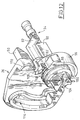
- the reference 26 generally has the form of a plate perpendicular to axis A2. It also includes a tubular socket 88 to the interior of which is intended to be received the rocket 82 of the rod 34. As can be seen for example in the figure 12, when the reference 26 is mounted on the control rod 34, it is substantially supported axially against the support plate 84 of the latter.
- Spring 90 is provided. 26 from its angular position of opening towards its angular position rest.
- Spring 90 is a helical spring with angular action which is intended to be arranged around the socket 88 of the reference 26 and which has two ends 92, 98 extending along a radius with respect to axis A2.
- a first of the ends 92 extends radially towards the exterior so as to be received in a notch 94 arranged in a flange 96 in the form of a half-ring which extends around of socket 88.
- the second end 98 of the spring 90 extends along a diameter of the propeller formed by this spring and it is intended to be received through a housing 100 which extends diametrically through a free end section 102 of the rocket 82 of the rod 34.
- the socket 88 of the reference 26 is thus immobilized axially with respect to the rod 34 on the one hand by the support plate 84 and secondly the second end 98 which plays the role of a pin.
- the free end 102 of the rocket 82 is shaped so that the second end 98 can be engaged in housing 100 in the axial direction rather only in the radial direction.
- a slot 104 is provided. which opens axially on the one hand into the housing 100 and, on the other hand, in a transverse end face of the rocket 82 and which extends along a diameter perpendicular to the diameter along which extends the general direction of housing 100.
- the support plate 84 has a stop 106 which extends axially along the direction of rocket 82 and which is intended to cooperate with a stop surface 108 complementary to the reference 26 to delimit the angular position of rest towards which the reference 26 is brought back by spring 90.
- Reference 26 also includes an immobilization finger 110 which extends axially along the axis A2, opposite a breakable lug 50.
- the immobilizing finger 110 is intended to be received in a housing 112 when the reference 26 is in its disengaged position, so as to prevent any rotation of the reference 26, the lock mechanism therefore no longer being able to be open.
- the reference 26 also includes a breakable lug 50 which extends axially from a lateral face of the reference 26, in front of the window 20 of the housing body 12 when the reference 26 is in disengaged position.
- the lug 50 is likely to cooperate with the push rod 18 of the pusher 14 to prevent it to be brought to its open position. Indeed, the lever 32 is then immobilized in the angular position of rest.
- the pusher 14 can then be brought to its position longitudinal opening but, the pusher 14 cannot cooperate with the articulated return 26 because it is then in position disengaged
- the pusher 14 is thus rendered inoperative in that it can no longer control the opening of the lock.
- the locking device is such that the pusher 14 is in retracted position of rest, and the reference 26 is in angular position of rest and in its active axial position in which it is likely to cooperate with the pusher 14.
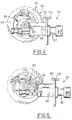
- the wheel gear 52 is then in a position such that the cam follower 62 is engaged in the end 60 of the cam track 56 which is radially outwardly relative to the axis A4 of the wheel toothed 52.
- control rod 34 is in its most on the left considering Figures 4 and 6. In this position, more particularly illustrated in FIG. 4, it can be seen that the reference 26 is arranged in the direction of the axis A2 of such so that the key 78 is able to cooperate with the end of the rod 18 of the pusher 14.
- the spring 16 brings the pusher 14 back to its retracted position and the spring 90 returns the reference 26 to its rest position.
- the user can then cause the locking of the device so that it is no longer possible to cause the opening of the lock.
- the electric motor 44 controls the electric motor 44, by example using a transponder to send an order of conviction to a central anti-theft system which causes the setting in route of the motor 44, which drives the wheel 52 in rotation in the clockwise considering for example Figure 4, until the wheel has reached its position illustrated in FIG. 5.
- the cam follower 62 is then received in the end 58 of the cam track 56 which is radially the further out from the A4 axis.
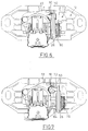
- the control rod 34 has moved to the right which has the consequence, when we consider the Figure 7, that the reference 26 is offset in the direction of the axis A2 relative to the axis A1 of the rod 18 of the pusher 14.
- the breakable lug 50 is then positioned just opposite the end of the rod 18 of the pusher 14.
- the rod 18 abuts against the breakable lug 50 which prevents any forward movement of pusher 14.
- the breakable lug 50 breaks so that the pusher 14 can then be brought back to its position advanced.
- the reference 26 which remains in the rest position so that the action on the pusher 14 remains without any effect on the lock which keeps the door closed.
Landscapes
- Lock And Its Accessories (AREA)
Applications Claiming Priority (2)
| Application Number | Priority Date | Filing Date | Title |
|---|---|---|---|
| FR9802741A FR2775719B1 (fr) | 1998-03-04 | 1998-03-04 | Dispositif de verrouillage pour un ouvrant de vehicule automobile comportant un renvoi pivotant debrayable en coulissement et commande par une came |
| FR9802741 | 1998-03-04 |
Publications (1)
| Publication Number | Publication Date |
|---|---|
| EP0940530A1 true EP0940530A1 (de) | 1999-09-08 |
Family
ID=9523731
Family Applications (1)
| Application Number | Title | Priority Date | Filing Date |
|---|---|---|---|
| EP99400465A Withdrawn EP0940530A1 (de) | 1998-03-04 | 1999-02-26 | Verriegelungsvorrichtung für einen Kraftfahrzeugsflügel mit einem drehbaren Element, das mittels eines Nockens in eine nicht gekuppelte Position verschoben werden kann |
Country Status (3)
| Country | Link |
|---|---|
| EP (1) | EP0940530A1 (de) |
| BR (1) | BR9900846A (de) |
| FR (1) | FR2775719B1 (de) |
Cited By (3)
| Publication number | Priority date | Publication date | Assignee | Title |
|---|---|---|---|---|
| FR2798950A1 (fr) * | 1999-09-29 | 2001-03-30 | Valeo Securite Habitacle | Dispositif de verrouillage comportant un doigt de transmission debrayable commande par came |
| WO2004101918A1 (de) * | 2003-05-17 | 2004-11-25 | Huf Hülsbeck & Fürst Gmbh & Co. Kg | Schliesseinrichtung für türen oder klappen von fahrzeugen |
| CN104265082A (zh) * | 2014-09-25 | 2015-01-07 | 深圳市金指纹科技有限公司 | 一种电子锁驱动机构 |
Citations (8)
| Publication number | Priority date | Publication date | Assignee | Title |
|---|---|---|---|---|
| GB2200397A (en) * | 1987-01-28 | 1988-08-03 | Ford Motor Co | Push-button lock |
| EP0293300A1 (de) * | 1987-05-27 | 1988-11-30 | Automobiles Peugeot | Fernbedienung für ein Schloss |
| US5234237A (en) * | 1992-05-11 | 1993-08-10 | General Motors Corporation | Modular van door latch |
| GB2265936A (en) * | 1992-04-04 | 1993-10-13 | Ford Motor Co | A door lock with disabling means for the handle |
| US5295374A (en) * | 1992-11-23 | 1994-03-22 | Chrysler Corporation | Tailgate handle assembly with window release switch |
| EP0791708A2 (de) * | 1996-02-26 | 1997-08-27 | Valeo Securite Habitacle | Verriegelungsvorrichtung eines Fahrzeugsflügels mit Mitteln zur Blockierung der Betätigungsgestange |
| DE19626914C1 (de) * | 1996-07-04 | 1997-10-09 | Huf Huelsbeck & Fuerst Gmbh | Verschluß für Türen, Hauben, Klappen o. dgl., insbesondere von Fahrzeugen, wie Kraftfahrzeugen |
| FR2755991A1 (fr) * | 1996-11-15 | 1998-05-22 | Valeo Securite Habitacle | Dispositif de fermeture et de verrouillage d'un ouvrant de vehicule automobile comportant un module de commande |
-
1998
- 1998-03-04 FR FR9802741A patent/FR2775719B1/fr not_active Expired - Fee Related
-
1999
- 1999-02-26 EP EP99400465A patent/EP0940530A1/de not_active Withdrawn
- 1999-03-02 BR BR9900846A patent/BR9900846A/pt not_active IP Right Cessation
Patent Citations (8)
| Publication number | Priority date | Publication date | Assignee | Title |
|---|---|---|---|---|
| GB2200397A (en) * | 1987-01-28 | 1988-08-03 | Ford Motor Co | Push-button lock |
| EP0293300A1 (de) * | 1987-05-27 | 1988-11-30 | Automobiles Peugeot | Fernbedienung für ein Schloss |
| GB2265936A (en) * | 1992-04-04 | 1993-10-13 | Ford Motor Co | A door lock with disabling means for the handle |
| US5234237A (en) * | 1992-05-11 | 1993-08-10 | General Motors Corporation | Modular van door latch |
| US5295374A (en) * | 1992-11-23 | 1994-03-22 | Chrysler Corporation | Tailgate handle assembly with window release switch |
| EP0791708A2 (de) * | 1996-02-26 | 1997-08-27 | Valeo Securite Habitacle | Verriegelungsvorrichtung eines Fahrzeugsflügels mit Mitteln zur Blockierung der Betätigungsgestange |
| DE19626914C1 (de) * | 1996-07-04 | 1997-10-09 | Huf Huelsbeck & Fuerst Gmbh | Verschluß für Türen, Hauben, Klappen o. dgl., insbesondere von Fahrzeugen, wie Kraftfahrzeugen |
| FR2755991A1 (fr) * | 1996-11-15 | 1998-05-22 | Valeo Securite Habitacle | Dispositif de fermeture et de verrouillage d'un ouvrant de vehicule automobile comportant un module de commande |
Cited By (4)
| Publication number | Priority date | Publication date | Assignee | Title |
|---|---|---|---|---|
| FR2798950A1 (fr) * | 1999-09-29 | 2001-03-30 | Valeo Securite Habitacle | Dispositif de verrouillage comportant un doigt de transmission debrayable commande par came |
| EP1088954A1 (de) * | 1999-09-29 | 2001-04-04 | Valeo Securité Habitacle | Verriegelungsvorrichtung mit einem mittels eines Nockens ausschaltbaren Übertragungsfinger |
| WO2004101918A1 (de) * | 2003-05-17 | 2004-11-25 | Huf Hülsbeck & Fürst Gmbh & Co. Kg | Schliesseinrichtung für türen oder klappen von fahrzeugen |
| CN104265082A (zh) * | 2014-09-25 | 2015-01-07 | 深圳市金指纹科技有限公司 | 一种电子锁驱动机构 |
Also Published As
| Publication number | Publication date |
|---|---|
| FR2775719A1 (fr) | 1999-09-10 |
| BR9900846A (pt) | 1999-12-28 |
| FR2775719B1 (fr) | 2000-04-07 |
Similar Documents
| Publication | Publication Date | Title |
|---|---|---|
| EP0088699B1 (de) | Schlüsselhalter mit einem in ein Gehäuse einklappbaren Schlüssel | |
| EP1611306B1 (de) | Schloss für eine öffnung an einem kraftfahrzeug mit einem gedächtnis zum entriegeln/verriegeln | |
| EP3404176B1 (de) | Vorrichtung zum entriegeln eines türschlosses | |
| FR2652318A1 (fr) | Retroviseur exterieur pour vehicule. | |
| FR2860261A1 (fr) | Dispositif de fermeture d'une ouverture et vehicule automobile correspondant | |
| EP0940530A1 (de) | Verriegelungsvorrichtung für einen Kraftfahrzeugsflügel mit einem drehbaren Element, das mittels eines Nockens in eine nicht gekuppelte Position verschoben werden kann | |
| EP0906997A1 (de) | Verriegelungsvorrichtung mit einem nockenbetätigten Übertragungselement | |
| EP1201851B1 (de) | Türgriffanordnung für eine Schiebetür eines Kraftfahrzeuges | |
| FR3098539A1 (fr) | Poignée d’ouvrant pour véhicule automobile | |
| EP1026350A1 (de) | Türgriff für Kraftfahrzeug | |
| FR2474573A1 (fr) | Dispositif d'actionnement electrique pour un organe de manoeuvre de serrures et objets analogues | |
| EP2071105A1 (de) | Schlüssel mit versenkbarem Einsatz | |
| EP0846603B1 (de) | Antrieb, insbesondere für eine elektrische Fahrzeugdiebstahlsicherung | |
| EP4321713B1 (de) | Verriegelungsvorrichtung für eine klappe eines fahrzeugs | |
| FR3107295A1 (fr) | Dispositif de verrouillage pour une pièce mobile d’un véhicule | |
| EP0724051B1 (de) | Türgriff eines Kraftfahrzeugs zur schnellen Montage durch ein System mit drehbaren Stiften | |
| FR2769036A1 (fr) | Dispositif de verrouillage comportant un doigt de transmission commande par une cremaillere | |
| FR2794791A1 (fr) | Perfectionnement a une serrure electrique, notamment pour portiere de vehicule automobile | |
| FR2487543A1 (fr) | Commande a manivelle | |
| EP1502829B1 (de) | Elektronische Steuer- und Diebstahlvorrichtung für ein Kraftfahrzeug mit dieser Vorrichtung | |
| EP3233587B1 (de) | Diebstahlschutzvorrichtung für lenksäule | |
| FR2798950A1 (fr) | Dispositif de verrouillage comportant un doigt de transmission debrayable commande par came | |
| FR2769038A1 (fr) | Dispositif de verrouillage comportant un doigt de transmission debrayable par basculement | |
| EP1053118B1 (de) | Betätigungsvorrichtung mit rastvorrichtung | |
| FR2777247A1 (fr) | Dispositif antivol pouvant etre fixe sur la couronne d'un volant de direction d'un vehicule automobile |
Legal Events
| Date | Code | Title | Description |
|---|---|---|---|
| PUAI | Public reference made under article 153(3) epc to a published international application that has entered the european phase |
Free format text: ORIGINAL CODE: 0009012 |
|
| AK | Designated contracting states |
Kind code of ref document: A1 Designated state(s): DE ES GB IT |
|
| AX | Request for extension of the european patent |
Free format text: AL;LT;LV;MK;RO;SI |
|
| 17P | Request for examination filed |
Effective date: 20000229 |
|
| AKX | Designation fees paid |
Free format text: DE ES GB IT |
|
| GRAG | Despatch of communication of intention to grant |
Free format text: ORIGINAL CODE: EPIDOS AGRA |
|
| 17Q | First examination report despatched |
Effective date: 20020605 |
|
| GRAG | Despatch of communication of intention to grant |
Free format text: ORIGINAL CODE: EPIDOS AGRA |
|
| GRAH | Despatch of communication of intention to grant a patent |
Free format text: ORIGINAL CODE: EPIDOS IGRA |
|
| STAA | Information on the status of an ep patent application or granted ep patent |
Free format text: STATUS: THE APPLICATION IS DEEMED TO BE WITHDRAWN |
|
| 18D | Application deemed to be withdrawn |
Effective date: 20030111 |