EP0940542A2 - Mécanisme de montage pour portes vitrées coulissantes. - Google Patents
Mécanisme de montage pour portes vitrées coulissantes. Download PDFInfo
- Publication number
- EP0940542A2 EP0940542A2 EP99500037A EP99500037A EP0940542A2 EP 0940542 A2 EP0940542 A2 EP 0940542A2 EP 99500037 A EP99500037 A EP 99500037A EP 99500037 A EP99500037 A EP 99500037A EP 0940542 A2 EP0940542 A2 EP 0940542A2
- Authority
- EP
- European Patent Office
- Prior art keywords
- baseplate
- recess
- suspension
- screw
- plates
- Prior art date
- Legal status (The legal status is an assumption and is not a legal conclusion. Google has not performed a legal analysis and makes no representation as to the accuracy of the status listed.)
- Granted
Links
- 230000007246 mechanism Effects 0.000 title claims abstract description 19
- 239000011521 glass Substances 0.000 title claims abstract description 17
- 239000000725 suspension Substances 0.000 claims abstract description 42
- 238000007373 indentation Methods 0.000 claims abstract description 12
- 238000005096 rolling process Methods 0.000 claims abstract description 5
- 238000006073 displacement reaction Methods 0.000 claims description 9
- 238000000605 extraction Methods 0.000 claims description 4
- 230000000903 blocking effect Effects 0.000 claims 1
- 230000000295 complement effect Effects 0.000 description 1
- 238000003754 machining Methods 0.000 description 1
- 239000000463 material Substances 0.000 description 1
- 230000000284 resting effect Effects 0.000 description 1
- 238000000926 separation method Methods 0.000 description 1
- 125000006850 spacer group Chemical group 0.000 description 1
Images


Classifications
-
- E—FIXED CONSTRUCTIONS
- E05—LOCKS; KEYS; WINDOW OR DOOR FITTINGS; SAFES
- E05D—HINGES OR SUSPENSION DEVICES FOR DOORS, WINDOWS OR WINGS
- E05D15/00—Suspension arrangements for wings
- E05D15/06—Suspension arrangements for wings for wings sliding horizontally more or less in their own plane
- E05D15/0621—Details, e.g. suspension or supporting guides
- E05D15/0626—Details, e.g. suspension or supporting guides for wings suspended at the top
- E05D15/063—Details, e.g. suspension or supporting guides for wings suspended at the top on wheels with fixed axis
-
- E—FIXED CONSTRUCTIONS
- E05—LOCKS; KEYS; WINDOW OR DOOR FITTINGS; SAFES
- E05Y—INDEXING SCHEME ASSOCIATED WITH SUBCLASSES E05D AND E05F, RELATING TO CONSTRUCTION ELEMENTS, ELECTRIC CONTROL, POWER SUPPLY, POWER SIGNAL OR TRANSMISSION, USER INTERFACES, MOUNTING OR COUPLING, DETAILS, ACCESSORIES, AUXILIARY OPERATIONS NOT OTHERWISE PROVIDED FOR, APPLICATION THEREOF
- E05Y2201/00—Constructional elements; Accessories therefor
- E05Y2201/60—Suspension or transmission members; Accessories therefor
- E05Y2201/622—Suspension or transmission members elements
- E05Y2201/64—Carriers
-
- E—FIXED CONSTRUCTIONS
- E05—LOCKS; KEYS; WINDOW OR DOOR FITTINGS; SAFES
- E05Y—INDEXING SCHEME ASSOCIATED WITH SUBCLASSES E05D AND E05F, RELATING TO CONSTRUCTION ELEMENTS, ELECTRIC CONTROL, POWER SUPPLY, POWER SIGNAL OR TRANSMISSION, USER INTERFACES, MOUNTING OR COUPLING, DETAILS, ACCESSORIES, AUXILIARY OPERATIONS NOT OTHERWISE PROVIDED FOR, APPLICATION THEREOF
- E05Y2600/00—Mounting or coupling arrangements for elements provided for in this subclass
- E05Y2600/50—Mounting methods; Positioning
- E05Y2600/502—Clamping
-
- E—FIXED CONSTRUCTIONS
- E05—LOCKS; KEYS; WINDOW OR DOOR FITTINGS; SAFES
- E05Y—INDEXING SCHEME ASSOCIATED WITH SUBCLASSES E05D AND E05F, RELATING TO CONSTRUCTION ELEMENTS, ELECTRIC CONTROL, POWER SUPPLY, POWER SIGNAL OR TRANSMISSION, USER INTERFACES, MOUNTING OR COUPLING, DETAILS, ACCESSORIES, AUXILIARY OPERATIONS NOT OTHERWISE PROVIDED FOR, APPLICATION THEREOF
- E05Y2600/00—Mounting or coupling arrangements for elements provided for in this subclass
- E05Y2600/60—Mounting or coupling members; Accessories therefor
- E05Y2600/628—Profiles; Strips
-
- E—FIXED CONSTRUCTIONS
- E05—LOCKS; KEYS; WINDOW OR DOOR FITTINGS; SAFES
- E05Y—INDEXING SCHEME ASSOCIATED WITH SUBCLASSES E05D AND E05F, RELATING TO CONSTRUCTION ELEMENTS, ELECTRIC CONTROL, POWER SUPPLY, POWER SIGNAL OR TRANSMISSION, USER INTERFACES, MOUNTING OR COUPLING, DETAILS, ACCESSORIES, AUXILIARY OPERATIONS NOT OTHERWISE PROVIDED FOR, APPLICATION THEREOF
- E05Y2800/00—Details, accessories and auxiliary operations not otherwise provided for
- E05Y2800/67—Materials; Strength alteration thereof
- E05Y2800/672—Glass
-
- E—FIXED CONSTRUCTIONS
- E05—LOCKS; KEYS; WINDOW OR DOOR FITTINGS; SAFES
- E05Y—INDEXING SCHEME ASSOCIATED WITH SUBCLASSES E05D AND E05F, RELATING TO CONSTRUCTION ELEMENTS, ELECTRIC CONTROL, POWER SUPPLY, POWER SIGNAL OR TRANSMISSION, USER INTERFACES, MOUNTING OR COUPLING, DETAILS, ACCESSORIES, AUXILIARY OPERATIONS NOT OTHERWISE PROVIDED FOR, APPLICATION THEREOF
- E05Y2900/00—Application of doors, windows, wings or fittings thereof
- E05Y2900/10—Application of doors, windows, wings or fittings thereof for buildings or parts thereof
- E05Y2900/13—Type of wing
- E05Y2900/132—Doors
Definitions
- the present invention refers to a mounting mechanism for sliding glass doors which does not require machining operations on the glass leaves and in addition allows an exact regulation of the height position.
- the mechanism of the invention is of the type which comprises an upper rail, a lower guide parallel to the upper rail and suspension heads which are attached to the upper edge of the door and have rolling elements which can move along the upper rail.
- the Spanish patent application no. 9300632 already informs of a mechanism of the type described, in which the suspension heads are composed of two back-to-back plates which can be attached to each other in a matching position, which on their opposing faces and from the lower edge have matching indentations which make up a lower recess which can be attached to the upper edge of the door.
- One of the plates which make up the suspension head has one or more free wheels mounted on its outer face.
- the upper rail is composed of an L-shaped bar with a horizontal branch which defines the track on which rest and may move the wheels of the suspension head.
- a further inconvenience of the mechanisms described is the difficulty of adjusting the door height, which is determined by the position of the rail.
- the upper rail consists of a tubular bar above the door and open longitudinally on its lower side. Inside this rail carriages may move which are connected to the door leaves by vertical screws anchored on their lower side to a mounting element which is embedded and attached to the door, on its upper edge.
- the Spanish patent application no. 9501409 of the same applicants may be mentioned.
- the object of the present invention is to eliminate the problems described by a mechanism of the type initially mentioned and which presents specific characteristics allowing mounting of one or more leaves in a small space, enough to house the leaves with their corresponding suspension heads.
- Another object of the invention is being able to adjust the height of the leave or leaves of the door, absorbing even certain tolerances or variations in the exact position of the upper rail and lower guide.
- the mechanism of the invention includes an upper rail and a lower guide between which are mounted the leave or leaves of the door and the suspension heads attachable to the upper edge of the door consisting of two back-to-back plates attachable to each other in a matching position.
- the plates which make up the suspension heads have, on their inner face and after their upper edge, respective matching longitudinal indentations which make up an upper recess when the plates are placed together.
- These indentations which make up the recess have in their turn an equal number of identical grooves or channels along their bottom which face each other and define longitudinal guides in the recess, between which is mounted, so that it may move longitudinally, a baseplate with an orifice through which a mounting screw passes to a carriage which is placed above the door and which may travel along the inside of the upper rail.
- the upper rail is composed of a tubular bar which is open on its lower side.
- the carriage or carriages joined to the suspension heads by the aforementioned mounting screw can travel along the inside of this bar.
- glass doors of two or more parallel leaves near each other may be mounted with sufficient room for the width of the suspension heads as the upper rail is above the leaves, as are the rolling elements.
- the upper recess of the suspension heads described, as well as the baseplates have means to limit the displacement of the baseplate once it is mounted on the recess guides between a position of maximum extraction in which the orifice for the screw to the carriage is left beyond the suspension head and an inner position in which the baseplate is completely housed in the recess.
- the suspension heads also have means to block the baseplate in its inner limit position, remaining locked there with no danger of accidental displacement when the door leaves are moved.
- the arrangement described also has the advantage of allowing adjusting the height of the leaves by the baseplate to carriage mounting screw, an operation which will be executed when the baseplate is in the position of maximum extraction. Once the height is adjusted the baseplate is moved to its inner position and locked.
- the upper recess of the suspension heads will have a width matching the head of the carriage mounting screw so that when the haseplate is moved to the inner position where the head of the screw is inside the recess, the screw cannot turn and accidentally loosen.
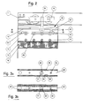
- Figure 1 is a front elevation of a mechanism in agreement with the invention for mounting two glass sliding doors with a cross section of the upper rail to show the movable carriages.
- Figure 2 shows enlargement A of figure 1, at a greater scale and in cross section.
- Figure 3a is a cross section of the suspension head along the III-III line of figure 2.
- Figure 3b is a view similar to figure 3a with a variation of execution.
- Figure 4 is a view similar to figure 2 with the baseplate to which is attached the mounting screw out of the suspension head.
- Figure 5a is a longitudinal cross section of the suspension head along the line V-V of figure.
- Figure 5b is a view similar to figure 5a showing a variation of execution.
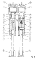
- Figure 6 shows a cross section of the suspension heads, upper rail and lower guide corresponding to the two leaves of the glass door.
- the door shown in figure 1 includes two glass leaves labeled 1 and 2, which are mounted by a mechanism which includes an upper rail for each door, labeled by numbers 3 and 4, and lower guides 5 and 6.
- Each of the doors has suspension heads mounted on top labeled 7 and 8.
- Upper rails 3 and 4 as seen in figure 6, are tubular in section and are open along the bottom side. Inside each rail carriages 9 and 10 are housed, connected to suspension heads 7 and 8 as described below.
- each of suspension heads 7 and 8 is composed of two rectangular plates 12, back-to-back and joined by screws 13. These plates have, on their inner face and from the lower edge, longitudinal indentations which define as the plates are joined a recess 15 which is connected to the upper edge of glass leaves 1 and 2.
- the inner surface of indentations 14 can be covered in a shock-absorbing and anti-skid material.
- Plates 12 also have on their inner surface and from the upper edge corresponding longitudinal indentations 17 which define as the plates are set, a longitudinal recess 18.
- Indentations 17 have identical grooves or channels 19 on the bottom, which are left facing each other and define in recesses 18 longitudinal guides between which is mounted a baseplate 20 which can move horizontally.
- This baseplate as seen in figures 3 and 5, has an orifice 21 through which screw 22 passes attaching it to the corresponding suspension carriage.
- Suspension heads have means in order to limit the displacement of baseplate 20. These means can consist of pins or bolts 23 mounted across plates 12, which are tangent to recess 18 and slightly project out from the bottom. These means complement screws 24 which are attached to baseplate 20 and which project from the bottom and act as limiting stops for the displacement of the baseplate as they collide with pins 23.
- baseplate 20 In the position shown in figure 2, baseplate 20 is housed completely inside recess 18 defined by plates 12, with screw 24 resting on one pin 23. In the position shown in figure 4, plate 20 is in the position of maximum extraction, screw 24 colliding with the other pin 23.
- baseplate 20 In the inner position of baseplate 20, shown in figures 2 and 3a, this position is locked by locking elements consisting of a pressure screw 25 inserted through a threaded orifice in one of plates 12 level with channel 19.
- Baseplate 20 has notches 26 in its longitudinal edges which lie opposite screw 25 in its inner position, as shown in figure 3. By tightening screw 25 it partially enters notches 26, stopping baseplate 200 from moving and perhaps projecting out from the suspension head accidentally, for example due to the displacement of the door leaves.
- baseplate 20 has a striation or groove 28, for example in its upper surface, which creates sufficient friction with channels 19 to prevent its accidental displacement.
- upper recess 18 of the suspension heads 7 and 8 is of the same width as the head of screw 22, at least in the segment located under channels 19. In this way screw 22 cannot turn once baseplate 20 is in its inner position of figures 2 and 3. Above channels 19 upper recess 18 can be of lesser width, enough to allow the pin of screw 22 to pass.
- Plates 12 which make up the suspension head have, along their upper and outer edges, grooves or channels 27 meant for attaching brushes which close against tubes 3 and 4 which make up the upper rails.
- heads 7 and 8 are shown in different cross sections in order to show in one case screw 13 for mounting of the two head plates and in the other case screw 22 for attaching the head to the corresponding carriage.
- screw 22 allows to adjust the height of the suspension head and with it that of the corresponding glass leaf.
- the heads of screws for attaching plates 12 of each suspension head can be hidden by decorative strips 30, figure 6, or coupled to a slight groove of said plates on their outside face, level with the passage orifices of these screws.
- each glass leaf 1 or 2 has two suspension heads 7 - 8
- a single head of length equal to the width of the leaf could be used, with the above described components on its ends.
Landscapes
- Engineering & Computer Science (AREA)
- Mechanical Engineering (AREA)
- Window Of Vehicle (AREA)
- Support Devices For Sliding Doors (AREA)
- Bearings For Parts Moving Linearly (AREA)
- Wing Frames And Configurations (AREA)
Priority Applications (1)
| Application Number | Priority Date | Filing Date | Title |
|---|---|---|---|
| DK99500037T DK0940542T3 (da) | 1998-03-06 | 1999-03-05 | Monteringsindretning til glasskydedöre |
Applications Claiming Priority (2)
| Application Number | Priority Date | Filing Date | Title |
|---|---|---|---|
| ES009800483A ES2180350B1 (es) | 1998-03-06 | 1998-03-06 | Mecanismo para el montaje de puertas corredizas de cristal. |
| ES9800483 | 1998-03-06 |
Publications (3)
| Publication Number | Publication Date |
|---|---|
| EP0940542A2 true EP0940542A2 (fr) | 1999-09-08 |
| EP0940542A3 EP0940542A3 (fr) | 2003-03-05 |
| EP0940542B1 EP0940542B1 (fr) | 2005-02-09 |
Family
ID=8303022
Family Applications (1)
| Application Number | Title | Priority Date | Filing Date |
|---|---|---|---|
| EP99500037A Expired - Lifetime EP0940542B1 (fr) | 1998-03-06 | 1999-03-05 | Mécanisme de montage pour portes vitrées coulissantes. |
Country Status (6)
| Country | Link |
|---|---|
| EP (1) | EP0940542B1 (fr) |
| AT (1) | ATE288991T1 (fr) |
| DE (1) | DE69923615T2 (fr) |
| DK (1) | DK0940542T3 (fr) |
| ES (2) | ES2180350B1 (fr) |
| PT (1) | PT940542E (fr) |
Cited By (12)
| Publication number | Priority date | Publication date | Assignee | Title |
|---|---|---|---|---|
| EP1359279A1 (fr) | 2002-04-23 | 2003-11-05 | Hawa Ag | Dispositif de support des plaques et élément de séparation |
| EP1405979A1 (fr) | 2002-10-02 | 2004-04-07 | Hawa Ag | Dispositif de liaison, dispositif de recouvrement et élément de partition |
| US7246411B2 (en) | 2003-12-19 | 2007-07-24 | Jeld-Wen, Inc. | Methods and systems for sliding windows and doors |
| EP1741862A3 (fr) * | 2005-06-27 | 2008-02-27 | Eclisse Srl | Dispositif de suspension pour portes coulissantes |
| EP1916370A1 (fr) * | 2006-10-19 | 2008-04-30 | Hawa Ag | Système de suspension avec un chariot pour panneaux coulissants |
| DE102007031829A1 (de) | 2007-06-28 | 2009-01-08 | Hidde, Axel R., Dr. | Laufschiene mit Rollenwagen und Beschlag für die Energie- und Nachrichtenübertragung |
| CH702258A1 (de) * | 2009-11-26 | 2011-05-31 | Eku Ag | Laufwerk für eine Schiebetür. |
| WO2012016689A1 (fr) * | 2010-08-06 | 2012-02-09 | Dorma Gmbh + Co. Kg | Chariot de porte coulissante modulaire |
| EP2281993A3 (fr) * | 2009-06-26 | 2014-07-30 | GEZE GmbH | Installation de porte en verre avec un élément de guidage |
| EP2789780A1 (fr) | 2013-04-09 | 2014-10-15 | Sliding S.R.L. | Dispositif de support et de réglage d'un chariot pour portes coulissantes |
| EP3029238A1 (fr) * | 2014-12-04 | 2016-06-08 | DORMA Deutschland GmbH | Ferrure d'angle dotée d'une plage de serrage réglable |
| EP3211164A1 (fr) * | 2016-02-23 | 2017-08-30 | Gebr. Willach GmbH | Système de porte coulissante |
Families Citing this family (3)
| Publication number | Priority date | Publication date | Assignee | Title |
|---|---|---|---|---|
| ES2265797B1 (es) * | 2006-07-24 | 2008-02-01 | Felix Ramirez Segundo | Mordaza corredera regulable. |
| DE102008004751B3 (de) | 2008-01-16 | 2009-08-06 | Geze Gmbh | Klemmbeschlag |
| DE202019106086U1 (de) | 2019-11-01 | 2021-02-03 | Pauli + Sohn Gmbh Metallwaren | Klemmvorrichtung für einen Türflügel |
Family Cites Families (4)
| Publication number | Priority date | Publication date | Assignee | Title |
|---|---|---|---|---|
| GB531950A (en) * | 1939-08-09 | 1941-01-14 | Viktor Kuhnlein | Improvements in sliding- and folding-doors and windows |
| DE3238204A1 (de) * | 1982-10-15 | 1984-04-19 | Pauli & Sohn GmbH Metallwaren, 5220 Waldbröl | Vorrichtung zur haengenden anbringung von scheiben an einer laufschiene |
| ES2084543B1 (es) * | 1993-03-26 | 1998-07-01 | Klein Iberica | Mecanismo para puertas corredizas de cristal. |
| ES2135990B1 (es) * | 1995-07-13 | 2000-05-01 | Klein Iberica | Estructura para el montaje de puertas correderas. |
-
1998
- 1998-03-06 ES ES009800483A patent/ES2180350B1/es not_active Expired - Fee Related
-
1999
- 1999-03-05 ES ES99500037T patent/ES2237066T3/es not_active Expired - Lifetime
- 1999-03-05 EP EP99500037A patent/EP0940542B1/fr not_active Expired - Lifetime
- 1999-03-05 PT PT99500037T patent/PT940542E/pt unknown
- 1999-03-05 DE DE69923615T patent/DE69923615T2/de not_active Expired - Lifetime
- 1999-03-05 DK DK99500037T patent/DK0940542T3/da active
- 1999-03-05 AT AT99500037T patent/ATE288991T1/de active
Cited By (17)
| Publication number | Priority date | Publication date | Assignee | Title |
|---|---|---|---|---|
| EP1359279A1 (fr) | 2002-04-23 | 2003-11-05 | Hawa Ag | Dispositif de support des plaques et élément de séparation |
| EP1405979A1 (fr) | 2002-10-02 | 2004-04-07 | Hawa Ag | Dispositif de liaison, dispositif de recouvrement et élément de partition |
| US7246411B2 (en) | 2003-12-19 | 2007-07-24 | Jeld-Wen, Inc. | Methods and systems for sliding windows and doors |
| EP1741862A3 (fr) * | 2005-06-27 | 2008-02-27 | Eclisse Srl | Dispositif de suspension pour portes coulissantes |
| CN101165302B (zh) * | 2006-10-19 | 2011-11-16 | 哈瓦有限公司 | 具有用于保持面板的传动机构的装置和隔离件 |
| EP1916370A1 (fr) * | 2006-10-19 | 2008-04-30 | Hawa Ag | Système de suspension avec un chariot pour panneaux coulissants |
| KR101379145B1 (ko) * | 2006-10-19 | 2014-03-28 | 하바 아게 | 패널을 지지하는 이송대를 가지는 장치와 그 구획부재 |
| AU2007221866B2 (en) * | 2006-10-19 | 2014-10-23 | Hawa Ag | Device with a carriage for holding panels and a separation element |
| DE102007031829A1 (de) | 2007-06-28 | 2009-01-08 | Hidde, Axel R., Dr. | Laufschiene mit Rollenwagen und Beschlag für die Energie- und Nachrichtenübertragung |
| EP2281993A3 (fr) * | 2009-06-26 | 2014-07-30 | GEZE GmbH | Installation de porte en verre avec un élément de guidage |
| CH702258A1 (de) * | 2009-11-26 | 2011-05-31 | Eku Ag | Laufwerk für eine Schiebetür. |
| WO2011063535A1 (fr) * | 2009-11-26 | 2011-06-03 | Eku Ag | Mécanisme de roulement pour une porte coulissante |
| WO2012016689A1 (fr) * | 2010-08-06 | 2012-02-09 | Dorma Gmbh + Co. Kg | Chariot de porte coulissante modulaire |
| EP2789780A1 (fr) | 2013-04-09 | 2014-10-15 | Sliding S.R.L. | Dispositif de support et de réglage d'un chariot pour portes coulissantes |
| EP3029238A1 (fr) * | 2014-12-04 | 2016-06-08 | DORMA Deutschland GmbH | Ferrure d'angle dotée d'une plage de serrage réglable |
| US9752379B2 (en) | 2014-12-04 | 2017-09-05 | Dorma Deutschland Gmbh | Corner fitting with adjustable restraining area |
| EP3211164A1 (fr) * | 2016-02-23 | 2017-08-30 | Gebr. Willach GmbH | Système de porte coulissante |
Also Published As
| Publication number | Publication date |
|---|---|
| DE69923615D1 (de) | 2005-03-17 |
| DE69923615T2 (de) | 2006-01-05 |
| EP0940542A3 (fr) | 2003-03-05 |
| EP0940542B1 (fr) | 2005-02-09 |
| ES2180350B1 (es) | 2004-03-16 |
| ES2180350A1 (es) | 2003-02-01 |
| ES2237066T3 (es) | 2005-07-16 |
| DK0940542T3 (da) | 2005-06-20 |
| ATE288991T1 (de) | 2005-02-15 |
| PT940542E (pt) | 2005-06-30 |
Similar Documents
| Publication | Publication Date | Title |
|---|---|---|
| EP0940542A2 (fr) | Mécanisme de montage pour portes vitrées coulissantes. | |
| US4581850A (en) | Combination pivot corner and slide guide for sash window | |
| US4054308A (en) | Lock for sliding closures | |
| US4208838A (en) | Latch hardware | |
| US3744827A (en) | Hardware for a sliding door installation | |
| EP1629169B1 (fr) | Guidage par rail pour element coulissant suspendu | |
| SK93497A3 (en) | Movable wall | |
| US3650071A (en) | Panel frame assembly | |
| US3281993A (en) | Reversible sliding door and window construction | |
| US2264020A (en) | Window construction | |
| DE10319170A1 (de) | Raumteiler | |
| EP1318258B1 (fr) | Ferrure d'un vantail ou d'un dormant d'une fenêtre, d'une porte ou similaire | |
| US6082050A (en) | Top hung sliding doors and windows | |
| EP0573819A3 (fr) | ||
| US3591984A (en) | Sliding door fitting comprising a cursor for guiding the door in a guide rail | |
| EP1061217A3 (fr) | Gâche avec lisières de contact pour crémone-serrures pour portes et fenêtres | |
| EP1693545B1 (fr) | Paroi coulissante en verre | |
| US3370383A (en) | Reversible sliding door and window construction | |
| DE202008004204U1 (de) | Schwelle für Gebäudetüren sowie Zusatzprofil zur Verwendung bei einer Schwelle bzw. einem Schwellenprofil für Gebäudetüren | |
| ITMI20000711A1 (it) | Rotaia di guida per un sistema di porta scorrevole di vetro | |
| DE29722616U1 (de) | Wandelement mit Durchgangstür für bewegliche Trennwände | |
| US3427059A (en) | Locking mechanism for sliding doors | |
| DE8617054U1 (de) | Schließteil zur Einbruchhemmung an Fenstern und Fenstertüren | |
| DE4300715C1 (de) | Führung für ein Türblatt einer Schiebetür | |
| US2310401A (en) | Window structure |
Legal Events
| Date | Code | Title | Description |
|---|---|---|---|
| PUAI | Public reference made under article 153(3) epc to a published international application that has entered the european phase |
Free format text: ORIGINAL CODE: 0009012 |
|
| AK | Designated contracting states |
Kind code of ref document: A2 Designated state(s): AT BE CH CY DE DK ES FI FR GB GR IE IT LI LU MC NL PT SE |
|
| AX | Request for extension of the european patent |
Free format text: AL;LT;LV;MK;RO;SI |
|
| PUAL | Search report despatched |
Free format text: ORIGINAL CODE: 0009013 |
|
| AK | Designated contracting states |
Kind code of ref document: A3 Designated state(s): AT BE CH CY DE DK ES FI FR GB GR IE IT LI LU MC NL PT SE Designated state(s): AT BE CH CY DE DK ES FI FR GB GR IE IT LI LU MC NL PT SE |
|
| AX | Request for extension of the european patent |
Extension state: AL LT LV MK RO SI |
|
| 17P | Request for examination filed |
Effective date: 20030829 |
|
| 17Q | First examination report despatched |
Effective date: 20031009 |
|
| AKX | Designation fees paid |
Designated state(s): AT BE CH CY DE DK ES LI |
|
| AXX | Extension fees paid |
Extension state: SI Payment date: 20030829 Extension state: RO Payment date: 20030829 Extension state: LV Payment date: 20030829 Extension state: LT Payment date: 20030829 |
|
| RBV | Designated contracting states (corrected) |
Designated state(s): AT BE CH CY DE DK ES FI FR GB GR IE IT LI LU MC NL PT SE |
|
| GRAP | Despatch of communication of intention to grant a patent |
Free format text: ORIGINAL CODE: EPIDOSNIGR1 |
|
| GRAS | Grant fee paid |
Free format text: ORIGINAL CODE: EPIDOSNIGR3 |
|
| GRAA | (expected) grant |
Free format text: ORIGINAL CODE: 0009210 |
|
| AK | Designated contracting states |
Kind code of ref document: B1 Designated state(s): AT BE CH CY DE DK ES FI FR GB GR IE IT LI LU MC NL PT SE |
|
| AX | Request for extension of the european patent |
Extension state: LT LV RO SI |
|
| REG | Reference to a national code |
Ref country code: GB Ref legal event code: FG4D |
|
| REG | Reference to a national code |
Ref country code: CH Ref legal event code: EP |
|
| PG25 | Lapsed in a contracting state [announced via postgrant information from national office to epo] |
Ref country code: CY Free format text: LAPSE BECAUSE OF FAILURE TO SUBMIT A TRANSLATION OF THE DESCRIPTION OR TO PAY THE FEE WITHIN THE PRESCRIBED TIME-LIMIT Effective date: 20050305 |
|
| REG | Reference to a national code |
Ref country code: IE Ref legal event code: FG4D |
|
| REF | Corresponds to: |
Ref document number: 69923615 Country of ref document: DE Date of ref document: 20050317 Kind code of ref document: P |
|
| REG | Reference to a national code |
Ref country code: SE Ref legal event code: TRGR |
|
| REG | Reference to a national code |
Ref country code: GR Ref legal event code: EP Ref document number: 20050401284 Country of ref document: GR |
|
| REG | Reference to a national code |
Ref country code: CH Ref legal event code: NV Representative=s name: MICHELI & CIE INGENIEURS-CONSEILS |
|
| REG | Reference to a national code |
Ref country code: DK Ref legal event code: T3 |
|
| REG | Reference to a national code |
Ref country code: PT Ref legal event code: SC4A Free format text: AVAILABILITY OF NATIONAL TRANSLATION Effective date: 20050421 |
|
| REG | Reference to a national code |
Ref country code: ES Ref legal event code: FG2A Ref document number: 2237066 Country of ref document: ES Kind code of ref document: T3 |
|
| LTIE | Lt: invalidation of european patent or patent extension |
Effective date: 20050209 |
|
| PLBE | No opposition filed within time limit |
Free format text: ORIGINAL CODE: 0009261 |
|
| STAA | Information on the status of an ep patent application or granted ep patent |
Free format text: STATUS: NO OPPOSITION FILED WITHIN TIME LIMIT |
|
| 26N | No opposition filed |
Effective date: 20051110 |
|
| ET | Fr: translation filed | ||
| REG | Reference to a national code |
Ref country code: FR Ref legal event code: PLFP Year of fee payment: 18 |
|
| REG | Reference to a national code |
Ref country code: FR Ref legal event code: PLFP Year of fee payment: 19 |
|
| REG | Reference to a national code |
Ref country code: FR Ref legal event code: PLFP Year of fee payment: 20 |
|
| PGFP | Annual fee paid to national office [announced via postgrant information from national office to epo] |
Ref country code: LU Payment date: 20180226 Year of fee payment: 20 Ref country code: DK Payment date: 20180312 Year of fee payment: 20 Ref country code: GB Payment date: 20180228 Year of fee payment: 20 Ref country code: CH Payment date: 20180314 Year of fee payment: 20 Ref country code: DE Payment date: 20180227 Year of fee payment: 20 Ref country code: NL Payment date: 20180314 Year of fee payment: 20 Ref country code: FI Payment date: 20180312 Year of fee payment: 20 |
|
| PGFP | Annual fee paid to national office [announced via postgrant information from national office to epo] |
Ref country code: FR Payment date: 20180227 Year of fee payment: 20 Ref country code: BE Payment date: 20180223 Year of fee payment: 20 Ref country code: SE Payment date: 20180313 Year of fee payment: 20 Ref country code: IE Payment date: 20180312 Year of fee payment: 20 Ref country code: PT Payment date: 20180219 Year of fee payment: 20 Ref country code: IT Payment date: 20180321 Year of fee payment: 20 Ref country code: MC Payment date: 20180228 Year of fee payment: 20 Ref country code: GR Payment date: 20180227 Year of fee payment: 20 Ref country code: AT Payment date: 20180226 Year of fee payment: 20 |
|
| PGFP | Annual fee paid to national office [announced via postgrant information from national office to epo] |
Ref country code: ES Payment date: 20180410 Year of fee payment: 20 |
|
| REG | Reference to a national code |
Ref country code: DE Ref legal event code: R071 Ref document number: 69923615 Country of ref document: DE |
|
| REG | Reference to a national code |
Ref country code: NL Ref legal event code: MK Effective date: 20190304 |
|
| REG | Reference to a national code |
Ref country code: DK Ref legal event code: EUP Effective date: 20190305 |
|
| REG | Reference to a national code |
Ref country code: CH Ref legal event code: PL |
|
| REG | Reference to a national code |
Ref country code: GB Ref legal event code: PE20 Expiry date: 20190304 |
|
| REG | Reference to a national code |
Ref country code: BE Ref legal event code: MK Effective date: 20190305 |
|
| REG | Reference to a national code |
Ref country code: AT Ref legal event code: MK07 Ref document number: 288991 Country of ref document: AT Kind code of ref document: T Effective date: 20190305 |
|
| REG | Reference to a national code |
Ref country code: IE Ref legal event code: MK9A |
|
| PG25 | Lapsed in a contracting state [announced via postgrant information from national office to epo] |
Ref country code: IE Free format text: LAPSE BECAUSE OF EXPIRATION OF PROTECTION Effective date: 20190305 Ref country code: GB Free format text: LAPSE BECAUSE OF EXPIRATION OF PROTECTION Effective date: 20190304 |
|
| PG25 | Lapsed in a contracting state [announced via postgrant information from national office to epo] |
Ref country code: PT Free format text: LAPSE BECAUSE OF EXPIRATION OF PROTECTION Effective date: 20190314 |
|
| REG | Reference to a national code |
Ref country code: ES Ref legal event code: FD2A Effective date: 20200904 |
|
| PG25 | Lapsed in a contracting state [announced via postgrant information from national office to epo] |
Ref country code: ES Free format text: LAPSE BECAUSE OF EXPIRATION OF PROTECTION Effective date: 20190306 |