EP3211164A1 - Système de porte coulissante - Google Patents
Système de porte coulissante Download PDFInfo
- Publication number
- EP3211164A1 EP3211164A1 EP17156122.8A EP17156122A EP3211164A1 EP 3211164 A1 EP3211164 A1 EP 3211164A1 EP 17156122 A EP17156122 A EP 17156122A EP 3211164 A1 EP3211164 A1 EP 3211164A1
- Authority
- EP
- European Patent Office
- Prior art keywords
- carriage
- fastening device
- running rail
- sliding door
- fastening
- Prior art date
- Legal status (The legal status is an assumption and is not a legal conclusion. Google has not performed a legal analysis and makes no representation as to the accuracy of the status listed.)
- Granted
Links
Images



Classifications
-
- E—FIXED CONSTRUCTIONS
- E05—LOCKS; KEYS; WINDOW OR DOOR FITTINGS; SAFES
- E05D—HINGES OR SUSPENSION DEVICES FOR DOORS, WINDOWS OR WINGS
- E05D15/00—Suspension arrangements for wings
- E05D15/06—Suspension arrangements for wings for wings sliding horizontally more or less in their own plane
- E05D15/0621—Details, e.g. suspension or supporting guides
- E05D15/0626—Details, e.g. suspension or supporting guides for wings suspended at the top
- E05D15/063—Details, e.g. suspension or supporting guides for wings suspended at the top on wheels with fixed axis
- E05D15/0634—Details, e.g. suspension or supporting guides for wings suspended at the top on wheels with fixed axis with height adjustment
-
- E—FIXED CONSTRUCTIONS
- E05—LOCKS; KEYS; WINDOW OR DOOR FITTINGS; SAFES
- E05F—DEVICES FOR MOVING WINGS INTO OPEN OR CLOSED POSITION; CHECKS FOR WINGS; WING FITTINGS NOT OTHERWISE PROVIDED FOR, CONCERNED WITH THE FUNCTIONING OF THE WING
- E05F1/00—Closers or openers for wings, not otherwise provided for in this subclass
- E05F1/08—Closers or openers for wings, not otherwise provided for in this subclass spring-actuated, e.g. for horizontally sliding wings
- E05F1/16—Closers or openers for wings, not otherwise provided for in this subclass spring-actuated, e.g. for horizontally sliding wings for sliding wings
-
- E—FIXED CONSTRUCTIONS
- E05—LOCKS; KEYS; WINDOW OR DOOR FITTINGS; SAFES
- E05F—DEVICES FOR MOVING WINGS INTO OPEN OR CLOSED POSITION; CHECKS FOR WINGS; WING FITTINGS NOT OTHERWISE PROVIDED FOR, CONCERNED WITH THE FUNCTIONING OF THE WING
- E05F5/00—Braking devices, e.g. checks; Stops; Buffers
- E05F5/003—Braking devices, e.g. checks; Stops; Buffers for sliding wings
-
- E—FIXED CONSTRUCTIONS
- E05—LOCKS; KEYS; WINDOW OR DOOR FITTINGS; SAFES
- E05Y—INDEXING SCHEME ASSOCIATED WITH SUBCLASSES E05D AND E05F, RELATING TO CONSTRUCTION ELEMENTS, ELECTRIC CONTROL, POWER SUPPLY, POWER SIGNAL OR TRANSMISSION, USER INTERFACES, MOUNTING OR COUPLING, DETAILS, ACCESSORIES, AUXILIARY OPERATIONS NOT OTHERWISE PROVIDED FOR, APPLICATION THEREOF
- E05Y2600/00—Mounting or coupling arrangements for elements provided for in this subclass
- E05Y2600/40—Mounting location; Visibility of the elements
- E05Y2600/456—Mounting location; Visibility of the elements in or on a suspension member
-
- E—FIXED CONSTRUCTIONS
- E05—LOCKS; KEYS; WINDOW OR DOOR FITTINGS; SAFES
- E05Y—INDEXING SCHEME ASSOCIATED WITH SUBCLASSES E05D AND E05F, RELATING TO CONSTRUCTION ELEMENTS, ELECTRIC CONTROL, POWER SUPPLY, POWER SIGNAL OR TRANSMISSION, USER INTERFACES, MOUNTING OR COUPLING, DETAILS, ACCESSORIES, AUXILIARY OPERATIONS NOT OTHERWISE PROVIDED FOR, APPLICATION THEREOF
- E05Y2800/00—Details, accessories and auxiliary operations not otherwise provided for
- E05Y2800/20—Combinations of elements
- E05Y2800/23—Combinations of elements of elements of different categories
- E05Y2800/24—Combinations of elements of elements of different categories of springs and brakes
-
- E—FIXED CONSTRUCTIONS
- E05—LOCKS; KEYS; WINDOW OR DOOR FITTINGS; SAFES
- E05Y—INDEXING SCHEME ASSOCIATED WITH SUBCLASSES E05D AND E05F, RELATING TO CONSTRUCTION ELEMENTS, ELECTRIC CONTROL, POWER SUPPLY, POWER SIGNAL OR TRANSMISSION, USER INTERFACES, MOUNTING OR COUPLING, DETAILS, ACCESSORIES, AUXILIARY OPERATIONS NOT OTHERWISE PROVIDED FOR, APPLICATION THEREOF
- E05Y2800/00—Details, accessories and auxiliary operations not otherwise provided for
- E05Y2800/67—Materials; Strength alteration thereof
- E05Y2800/672—Glass
Definitions
- the present invention relates to a sliding door system comprising at least one longitudinally extending track and a door leaf guided therefrom with at least one drive, the carriage having a carriage guided in the track and a mounting device connected to the carriage via which the carriage is mounted on an upper carriage Edge of the door is attached.
- sliding door systems are well known.
- the running rail has a track for the drive, wherein the carriage of the drive on one side has one or more rollers, which are guided in the track.
- the door leaf with mounted drive is usually mounted in the running rail from the longitudinal side of the running rail during assembly.
- the sliding door system according to the invention is defined by the features of claim 1.
- the method according to the invention is defined by the features of claim 12.
- the sliding door system has at least one running rail extending in a longitudinal direction and a door leaf guided thereon with at least one drive, the drive having a carriage guided in the running rail and a fastening device connected to the carriage. About the fastening device, the drive is attached to an upper edge of the door leaf.
- the invention is characterized in that the carriage for connection to the fastening device in the inserted state in the running rail in the longitudinal direction of the running rail and can be brought into contact with the fastening device, wherein the carriage arranged in the longitudinal direction of the running rail on the side facing the fastening device side Contact surface on a mating contact surface of Fastening device is applied and fastened via at least one fastening means to the fastening device.
- the sliding door system according to the invention allows a particularly simple installation, since the door can be arranged with attached to the door mounting device below the track and a mounting can be done in a simple manner by the carriage is pushed in the longitudinal direction of the track on the fastening device and is fastened by means of the at least one fastening means to the fastening device.
- two or more fastening means may be provided.
- fastening means for example screws can be provided.
- the carriage is arranged substantially above the door leaf and can thus be displaced along the running rail in an advantageous manner in order to be brought into contact with the fastening device.
- the carriage and the fastening device can be connected in a particularly simple manner, the contact surface and the mating contact surface being pressed against one another via the fastening means.
- the contact surface and the mating contact surface form a frictional connection.
- This has the advantage that after releasing the fastening means, the contact surface and the mating contact surface can slide freely one above the other at a height adjustment.
- Centering means may also be provided to assist alignment of the contact surface and mating contact surface.
- the door leaf with several Drives is performed, each having a carriage and a fastening device.
- the at least one fastening means extends in the longitudinal direction of the running rail.
- Such fasteners have been found to be particularly advantageous. Furthermore, it can be achieved with such a construction that the fastening means are loaded substantially to train.
- the at least one fastening means preferably has an operating element on its side facing the first side edge of the door leaf in the longitudinal direction of the running rail.
- the carriage can be fastened to the fastening device in a particularly advantageous manner by operating the fastening means from the front side of the door leaf.
- the sliding door system according to the invention can thus provide, in the state of the carriage fastened to the fastening means, that the at least one fastening means extends in the longitudinal direction of the running rail and preferably has an operating element on its side facing the first side edge of the door leaf in the longitudinal direction of the running rail.
- the drive is arranged on the door leaf with a predetermined distance D extending in the longitudinal direction of the track rail from the first side edge of the door leaf.
- the distance D is measured from the side edge of the door leaf to the edge of the drive facing the side edge of the door leaf.
- the predetermined distance D may be, for example, a maximum of 10% of the door leaf width. This ensures that the at least one fastening means for fastening the carriage to the fastening device can be conveniently operated from the first side edge of the door leaf.
- the drive has a height adjustment, by means of which the carriage and the fastening device in the vertical direction are adjustable relative to each other.
- the height adjustment can thus adjust the altitude of the door in an advantageous manner. It can be provided that the height adjustment takes place before the at least one fastening means connects the carriage and the fastening device firmly together. After the height adjustment can then be braced by means of fasteners trolley and fixture.
- the carriage is arranged on the side of the fastening device facing the first side edge of the door leaf in the longitudinal direction of the running rail, wherein the fastening means extends through the carriage.
- the fastening means engages in this embodiment in the fastening device.
- the fastening means can either detachably engage in the fastening device, for example by means of a screw thread or can also be firmly connected to the fastening device, wherein on the side facing away from the fastening device side of the carriage, the fastening means has a fastening part, by means of which the carriage is pressed against the fastening device ,
- the fastening means may be, for example, bolts which are inserted through the carriage and engage in a thread in the fastening device.
- stud bolts can also be provided as fastening means, which are fixedly arranged on the fastening device and onto which the carriage is pushed.
- nuts can, for example, sleeve nuts, be provided as a fastening part, which press the carriage against the fastening device. It is thus achieved that the carriage, which is arranged at least partially in the longitudinal direction of the running rail next to the fastening device is, can be arranged very close to the first margin. If the door is guided with two drives, it can be achieved that the distance of the carriage to each other in the longitudinal direction of the track is very large, whereby a particularly advantageous guidance of the door is achieved. In such an arrangement can of course also be provided that the fastening means engages in the carriage and penetrates the fastening device, for example by a counter-contact surface forming part.
- the fastening means is guided in the carriage or in the fastening device through a slot.
- an adjustment of the carriage relative to the fastening device in the vertical direction by means of the height adjustment can be realized in a simple manner, since the carriage is guided on the fastening means and has a corresponding freedom of movement in the vertical direction through the slot.
- the height adjustment may have an adjusting screw extending through the carriage, which presses against a sloping flank of the fastening device, wherein the adjusting screw extends through the carriage and has an operating element on its side facing the first side edge of the door leaf.
- the adjusting screw for example, have a ball head, which presses against the inclined edge.
- the inclined flank may be made of a different material than the fastening device, which is made of aluminum, for example, made of stainless steel.
- the inclined flank can be formed by inclined surfaces on the clamping jaws. When mounted on a door panel state, the inclined surfaces of the jaws may be spaced apart, so that the inclined edge has a gap. About the gap, a ball head of the adjusting be performed in an advantageous manner.
- Such height adjustment has been found to be particularly advantageous.
- a very fine height adjustment can be done by the adjusting screw is rotated.
- the adjusting screw may have a stop, over which the adjustment of the adjusting screw is limited. This prevents that the adjusting screw is screwed in too far, whereby the carriage could be pushed away from the fastening device.
- the fastening means or the fastening screw and the adjustment screw extend through the fastening device, for example through a part forming the mating contact surface, and engage in the carriage or abut against it. It can be provided that the carriage is arranged on the side facing away from the first side edge of the door leaf side of the fastening means.
- the fastening device has a flange projection, which engages in the longitudinal direction of the running rail in a recess of the carriage, preferably a form-fitting manner.
- a centering of the fastening device is achieved to the carriage, so that the fastening means can engage in an advantageous manner in the fastening device.
- the fastening means engages in the flange projection.
- the flange projection may form the mating contact surface.
- the fastening device may have projections which are in a state attached to the door leaf Fastening device form a gap to the door leaf. In this gap Zentriervorsprünge the drive can be performed, whereby an additional centering takes place.
- the fastening device is designed as a clamping device which has jaws on both sides of the door leaf.
- a clamping device which has jaws on both sides of the door leaf.
- the fastening device can be fastened in a clamping manner on the door leaf and thus elaborate bores on the glass can be avoided.
- At the jaws can be arranged on the side facing the first side edge, the projections.
- the carriage has an adapter element which is inserted in a passage recess in the carriage, wherein the fastening means is guided in the adapter element.
- an adapter element is advantageous because the parts in which the fastener is guided and to which the fastener is applied for tightening, can be made of a different material than the rest of the carriage.
- the slot may be arranged.
- the adjusting screw of the height adjustment can extend through the adapter element.
- the adapter element can be exchanged in a simple manner, if the adapter element due to, for example, the fastening means shows signs of wear. In this case, not the entire carriage must be replaced, but it can only be replaced, the adapter element.
- the adapter element may, for example, on the side facing the first side edge have a pressure plate over which the Adapter element is mounted in the carriage and forms a contact surface for the or the fastening means.
- the adapter plate may be made of a low-wear material, such as steel, whereby a depression of the or the fastening means in the attachment of the carriage is prevented.
- the adapter element can be positively received in the carriage. This ensures that, for example, the slot for the fastening means is aligned in the connection with the fastening device to the corresponding point of engagement for the fastening means on the fastening device.
- the adapter element may have a projection which engages in a gap of the fastening device to form an anti-rotation device.
- the rotation can also be effected by the centering projections on the carriage, which cooperate with the projections of the fastening device.
- the sliding door system preferably has a damper unit with retraction function and a coupler which engages with an engaging part of the damper unit detent, wherein the damper unit first decelerates the door during the process towards an end position and then drives into an end position.
- a damper unit with retraction function ensures that the door is reliably moved, for example, when closing the door in the closed position.
- the damper unit extends in the longitudinal direction of the running rail and is arranged on the carriage on the side remote from the first side edge of the door leaf side and that the coupler is attached to the running rail.
- the coupler may for example form a structural unit with a limiting device.
- the engaging part of the damper unit is directed upward.
- the coupler thus runs above the door leaf.
- the running rail can be made narrow in a visually appealing manner.
- the coupler can be designed, for example, as an elongate arm which extends in the longitudinal direction of the running rail. This may have at its end remote from the limiting device end a centering stone, which engages in a groove in the running rail. This ensures that the coupler is centered and can not move laterally or upwards in the interaction with the damper unit. This ensures a reliable function.
- the centering stone can be guided in a slot.
- the position of the centering stone in the longitudinal direction of the coupler is variable. Since the groove, which engages in the centering stone, is also used for receiving a screw head of a mounting screw of the track, it is ensured by the variable position of the centering stone that it can reliably engage in the groove and is not in the position of a fastening screw.
- the coupler may be formed as an elongate arm having a recess at a first end with which the coupler cooperates with the engaging portion. With the remote from the recess second end of the arm is at one Clamping device attached. The limiting device can engage in the running rail and be clamped in this. Thus, the coupler is set on the limiting device in the track.
- a height adjustment screw can be provided by means of which the height position of the coupler is adjustable.
- the height adjustment screw presses the arm formed as a coupler slightly upwards, whereby a slight, due to the weight of the coupler resulting deflection of the coupler can be compensated, so that the recess of the coupler is in the correct height position and does not threaten to collide with the carriage ,
- the height adjustment screw in the coupler for example, have a stop, so that the height adjustment is limited.
- the design of the coupler with the centering stone and the height-adjustable attachment of the coupler to the limiting device also have independent inventive significance and are independent of the design of the carriage and the fastening device realized.
- the damper unit has an axis which engages in the carriage. About the axis, the damper unit can be connected to the carriage. A Such structural design has been found to be particularly advantageous.
- the carriage has at least one roller, which is arranged on a roller block, wherein the roller block is mounted on the axis of the damper unit.
- the mounted on the axis of the damper unit roller block relative to the carriage frame can exert a twisting motion, so that the mounting device and the carriage frame can always remain vertically aligned even with a slightly twisted track and the deviations of the track by a twisting movement of the roller block on the axle can be compensated.
- roller blocks are arranged on the axle.
- rollers are arranged on both sides of the roller block or the roller blocks.
- the running rail in this case has two raceways in which the rollers can roll.
- a sliding door system may be provided with at least one longitudinally extending track and a run therefrom with at least one door leaf, the drive having a run in the track rail carriage, in which a damper unit is provided with catchment function, the door during the door Process in the direction initially decelerates an end position and then drives to an end position, wherein the damper unit extends in the longitudinal direction of the running rail and the damper unit has an axis which engages in the carriage, wherein a roller of the carriage is arranged on a roller block, on the axis of the damper unit is stored.
- the damper unit can be attached to the carriage.
- the sliding door system according to the invention can be designed, in particular, as a glass sliding door with door wings made of glass. It can also be provided several leaves, which are guided in several rails. For example, two drives can be arranged on each door leaf, which are respectively fastened in the vicinity of a side edge of the door leaf. In this case, provision is made in particular for the carriage to be fastened to the respective fastening device on the side facing the corresponding side edge of the door.
- a damper unit with a pull-in function is arranged on the front drive of each door leaf in the direction of closing the door leaf. Since the individual door leaves are coupled together in sliding door systems with a plurality of door leaves, it is thus prevented that when closing the door a single door leaf, for example the foremost door leaf, has to decelerate all other door leaves, but the door leaves are slowed down individually by means of the corresponding associated damper unit and led to their final position. Since the damper units used thus only have to slow down the mass of a door leaf, they can be configured correspondingly smaller.
- damper units may be provided, for example, on the two drives arranged on a door leaf.
- damper units may be provided, for example, on the two drives arranged on a door leaf.
- the design of the sliding door system with dampers for each door at one or both end positions also has independent inventive significance and is independent of the previously described embodiments of the carriage and the fastening device or the coupler and the limiting device or the damper unit with extending into the carriage axis realizable.
- the method may provide that the fastening device is arranged at the mounting on the upper edge of a door leaf with a distance D 'from a first side edge of the door leaf.
- the distance D ' is selected so that after attachment of the carriage to the fastening device of the first side edge of the door panel facing edge of the drive is arranged at a predetermined distance D.
- the predetermined distance D may be, for example, a maximum of 10% of the door leaf width. This ensures that the drive from the first side edge is advantageously accessible during assembly.
- the carriage is fastened to the fastening device by means of at least one fastening means extending in the longitudinal direction of the track rail.
- the fastening means may have, for example, an operating element on the side facing the first side edge of the door leaf, so that it can be operated in an advantageous manner from this side.
- the inventively provided predetermined distance D ensures that the fastener is easily accessible during installation.
- the height of the sliding door can be adjusted during assembly in a simple manner.
- the height adjustment presses by means of an adjusting screw against a sloping edge of the fastening device and the carriage and the fastening device are clamped by means of the fastening means.
- Such a method for attachment of carriage and fastening device has been found to be particularly advantageous.
- the inventive method can be provided in particular during the assembly of a sliding door system according to the invention.
- FIG. 1 an inventive sliding door system 1 is shown schematically in a side view.
- the sliding door system 1 has a door leaf 3, which is guided by means of a drive 5 in a longitudinally extending track rail 7.
- the running rail 7 is shown partially cut.
- the drive 5 consists of a run in the running rail 7 carriage 9 and a fixed to the carriage 9 fastening device 11.
- the fastening device 11 is fixed to an upper edge 3 a of the door leaf 3.
- the fastening device 11 is arranged at a distance D 'to a first side edge 3b of the door leaf 3, which is selected so that the first side edge 3b facing edge 5a of the drive 5 is spaced at a predetermined distance D from the first side edge 3b.
- the predetermined distance D is, for example, at most 10% of the width of the door leaf 3, so that the carriage 9 can be reached in an advantageous manner from the first side edge 3b.
- a damper unit 12 is arranged with retraction function, which initially slows down the door 3 during the process in the direction of an end position and then drives into the end position.
- position of the door 3 is immediately before an end position.
- a limiting device 13 is arranged in the form of a stop, which forms a structural unit with a coupler 15.
- the coupler 15 is formed as an arm extending in the longitudinal direction of the track rail 7 and cooperates with an engaging portion 17 of the damper unit 12.
- the damper unit 12 is arranged on the carriage on the side facing away from the first side edge 3b of the door leaf 3 and extends above the fastening device 11.
- the engaging part 17 of the damper unit 12 is after directed above.
- the coupler is arranged in the running rail such that it extends at least partially above the drive 5.
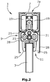
- the carriage 9 on both sides of rollers 19 which are guided in parallel tracks 21 of the track rail 7.
- the carriage 9 extends with its frame 9 b through a gap 23 which is formed between the raceways 21.
- the fastening device 11 is designed as a clamping device and has on both sides of the door leaf 3 jaws 25. In this way, the door leaf 3 can be positively connected to the fastening device 11 in an advantageous manner.
- the door leaf 3 may for example be a glass door leaf, so that the fastening device 11 can be fastened in an advantageous manner by clamping on the door leaf 3.
- Apertures 28 can be provided on the running rail 7, which at least partially optically obscure the fastening device 11, as a result of which a visually appealing sliding door system 1 can be created.
- the running rail 7 has a groove 7a in an upwardly directed portion. When fastening the running rail 7 to a ceiling screw heads of a screw fastening for the running rail 7 can be added in this groove.
- the coupler 15 formed as an arm is guided by means of a centering block 15a.
- the centering stone 15a is best from the Figures 1 and 1b seen.
- the centering stone 15a is guided in a slot 15b of the coupler 15 and can be set in this.
- the position of the centering block 15a on the coupler 15 can be varied so that the centering block 15a can be prevented from colliding with a fixing screw of the track rail 7.
- the coupler 15 has a recess 15c, which cooperates with the engagement part 17 of the damper unit.
- a height adjustment is provided on the coupler 15.
- the coupler 15 is connected via a screw 13a to the limiting device 13.
- a height adjustment screw 13b is provided, which presses from below against the coupler 15 and thus slightly elastically deformed. Thereby, the position of the end facing away from the limiting device of the coupler 15 and the recess 15 c can be adjusted.
- the sliding door system 1 enables a simplified assembly, which in FIGS. 3 and 4 is shown. For clarification purposes is in the FIGS. 3 and 4 the track is hidden.
- the fastening device 11 is attached to the upper edge 3 a of the door leaf 3.
- the running rail is fastened to its installation location.
- the door leaf is arranged below the running rail.
- the end faces of the running rail are no longer accessible after assembly of the running rail 7. In this case, the carriage 9 must be introduced into the running rail 7 before the mounting of the running rail 7.
- the carriage 9 is pushed in the longitudinal direction of the running rail 7 in the direction of the fastening device 11 until the carriage 9 with a contact surface 9a, which is arranged on the fastening device 11 facing side of the carriage 9, abuts against a mating contact surface 11a of the fastening device 11.
- This condition is in the Fig. 4 shown.
- fastening means 27a, 27b which in the embodiment shown in the figures as in the longitudinal direction of the running rail 7 extending Stud bolts 27b are formed with sleeve nuts 27a, the carriage 9 can be attached to the fastening device 11.
- the fastening means 27a, 27b are guided in oblong holes 29 in the carriage 9 and penetrate the carriage 9.
- the long cross-section of the elongated holes 29 extends in the vertical direction, whereby the fastening means 27a, 27b have freedom of movement in this direction.
- the elongated holes 29 are formed in an adapter element 31.
- the adapter element 31 is inserted from the side facing the first edge 3b of the door leaf 3 in the carriage 9 and received in a form-fitting manner.
- the studs 27 b are fixed to the fastening device 11.
- the carriage 9 is pushed onto the stud bolts 27b, so that the stud bolts 27b extend through the slots 29.
- the sleeve nuts 27a are screwed onto the stud bolts 27b.
- the sleeve nuts 27a have a receiving opening with an internal thread.
- the sleeve nuts In the front region of the receiving opening, the sleeve nuts have a cylindrical bore, which then merges into the thread which cooperates with the stud bolts 27b.
- the cylindrical bore has the advantage that over these the ends of the studs 27b can be performed and thus the sleeve nuts 27a can be placed on the stud bolts 27b in an advantageous manner.
- the mating contact surface 11a of the fastening device 11 is arranged on a flange projection 32, which engages in the longitudinal direction of the running rail in a recess 33 of the carriage 9.
- a centering of the fastening device 11 and the carriage 9 takes place, so that it is ensured that the fastening means 27b can engage in the corresponding holes in the carriage 9.
- the centering also takes place at the Fastening device 11 arranged projections 45 which form a gap to the door leaf 3 and engage in the centering projections 26 of the carriage 9.
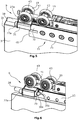
- FIGS. 5 and 6 To illustrate the internal structure of the carriage 9 are in FIGS. 5 and 6 individual elements of the carriage 9 shown in detail, wherein the frame of the carriage 9 is hidden for clarification purposes. In Fig. 6 Furthermore, one of the jaws 25 is not shown.
- the drive 5 according to the invention has a height adjustment, which has an adjusting screw 38.
- the adjusting screw 38 and the fastening means 27a have, on the side facing the first side edge 3b, in each case an operating element which is designed in the form of a head with an engagement opening for a tool.
- the adjusting screw 38 presses via a ball head 38a against a sloping flank 39 of the fastening device 11.
- the inclined flank 39 is in Fig. 6 shown in which the front jaw 25 is hidden for clarity purposes.
- the adjusting screw 38 is a vertical adjustment of carriage 9 and fastening device 11 relative to each other in a simple manner achievable.
- the inclined flank 39 is formed by inclined surfaces of the clamping jaws 25. Between the inclined surfaces, a gap 39 a is formed in the mounted state, which in Fig. 3 is indicated.
- the slit 39a forms a guide for the ball head 38a of the adjusting screw 38.
- the oblique surfaces are formed by inserts embedded in the clamping jaws 25 39b, which may be made of stainless steel, for example, and thus are wear-resistant.
- the adjusting screw 38 may have a stop which limits the adjustment path of the adjusting screw 38 and thus prevents the carriage 9 from being pushed away from the fastening device 11 via the adjusting screw.
- the adjusting screw 38 extends to the first side edge 3b of the door leaf 3, whereby an advantageous operation is ensured.
- the damper unit 12 has an axle 41, which engages in the carriage 9. By means of the axle 41, the damper unit 12 is attached to the carriage 9.
- the axle 41 extends into the frame 9b of the carriage.
- the rollers 19 are each arranged on both sides on a roller block 43 which is mounted on the axle 41.
- the individual roller blocks 43 can perform a pivoting movement relative to the carriage 9.
- the door leaf 3 can also be guided with, for example, two drives 5. It is preferably provided that the second drive 5 is arranged mirror-inverted to the first drive 5 and is aligned corresponding to the second side edge opposite the first side edge 3b.
- the sliding door system 1 may also have a plurality of door leaves 3, which are guided in parallel rails 7.
- each drive 5 must have a damper unit 12.
- each drive 5 may have a damper unit 12.
- each door leaf 3 can be guided over two drives 5, wherein each drive 5 has a damper unit 12.
- the damper units 12 of the drives 5 of a door leaf 3 are arranged laterally reversed.
- the damper units 12 brake the door leaves each in their driving in their final position and guide them reliably to the final position.
- By providing arranged laterally arranged damper units 12 and at the appropriate place in the running rail 7 couplers 15 can thus be ensured that each door is performed braked both in its opening and in its closed position.
- sliding door systems with multiple door leaves 3 These are usually coupled, thus preventing a door to slow down all the others with.
- each door has only one damper unit 12, and that, for example, the door wings are braked and pulled only when driving in the closed position.
Landscapes
- Engineering & Computer Science (AREA)
- Mechanical Engineering (AREA)
- Support Devices For Sliding Doors (AREA)
Applications Claiming Priority (1)
| Application Number | Priority Date | Filing Date | Title |
|---|---|---|---|
| DE102016202774.3A DE102016202774A1 (de) | 2016-02-23 | 2016-02-23 | Schiebetürsystem |
Publications (2)
| Publication Number | Publication Date |
|---|---|
| EP3211164A1 true EP3211164A1 (fr) | 2017-08-30 |
| EP3211164B1 EP3211164B1 (fr) | 2020-04-01 |
Family
ID=58043978
Family Applications (1)
| Application Number | Title | Priority Date | Filing Date |
|---|---|---|---|
| EP17156122.8A Active EP3211164B1 (fr) | 2016-02-23 | 2017-02-14 | Système de porte coulissante |
Country Status (3)
| Country | Link |
|---|---|
| EP (1) | EP3211164B1 (fr) |
| DE (1) | DE102016202774A1 (fr) |
| ES (1) | ES2788651T3 (fr) |
Families Citing this family (3)
| Publication number | Priority date | Publication date | Assignee | Title |
|---|---|---|---|---|
| DE102018200557A1 (de) | 2018-01-15 | 2019-07-18 | Gebr. Willach Gmbh | Schiebetürsystem mit mindestens einem Türflügel |
| DE102019117400A1 (de) * | 2019-06-27 | 2020-12-31 | Gebr. Willach Gmbh | Schiebetürsystem |
| DE102020100657A1 (de) | 2020-01-14 | 2021-07-15 | Gebr. Willach Gmbh | Schiebetürsystem |
Citations (4)
| Publication number | Priority date | Publication date | Assignee | Title |
|---|---|---|---|---|
| US904393A (en) * | 1908-04-01 | 1908-11-17 | Edson G Worden | Door-hanger. |
| EP0940542A2 (fr) * | 1998-03-06 | 1999-09-08 | Klein Iberica, S.A. | Mécanisme de montage pour portes vitrées coulissantes. |
| CH702258A1 (de) * | 2009-11-26 | 2011-05-31 | Eku Ag | Laufwerk für eine Schiebetür. |
| EP2886769A1 (fr) * | 2013-12-20 | 2015-06-24 | Argent Alu nv | Dispositif de roulement pour un mécanisme de porte coulissante et un procédé de montage d'un mécanisme de porte coulissante |
Family Cites Families (2)
| Publication number | Priority date | Publication date | Assignee | Title |
|---|---|---|---|---|
| US20060236613A1 (en) * | 2004-04-22 | 2006-10-26 | Ewing K B | Thermally broken hanging panel system |
| EP2899351B1 (fr) * | 2014-01-28 | 2018-01-31 | Terno Scorrevoli S.p.A. Unipersonale | Support pour portes coulissantes à ajustement et verrouillage latéraux et profilé métallique |
-
2016
- 2016-02-23 DE DE102016202774.3A patent/DE102016202774A1/de not_active Withdrawn
-
2017
- 2017-02-14 ES ES17156122T patent/ES2788651T3/es active Active
- 2017-02-14 EP EP17156122.8A patent/EP3211164B1/fr active Active
Patent Citations (4)
| Publication number | Priority date | Publication date | Assignee | Title |
|---|---|---|---|---|
| US904393A (en) * | 1908-04-01 | 1908-11-17 | Edson G Worden | Door-hanger. |
| EP0940542A2 (fr) * | 1998-03-06 | 1999-09-08 | Klein Iberica, S.A. | Mécanisme de montage pour portes vitrées coulissantes. |
| CH702258A1 (de) * | 2009-11-26 | 2011-05-31 | Eku Ag | Laufwerk für eine Schiebetür. |
| EP2886769A1 (fr) * | 2013-12-20 | 2015-06-24 | Argent Alu nv | Dispositif de roulement pour un mécanisme de porte coulissante et un procédé de montage d'un mécanisme de porte coulissante |
Also Published As
| Publication number | Publication date |
|---|---|
| DE102016202774A1 (de) | 2017-08-24 |
| ES2788651T3 (es) | 2020-10-22 |
| EP3211164B1 (fr) | 2020-04-01 |
Similar Documents
| Publication | Publication Date | Title |
|---|---|---|
| EP1197319B2 (fr) | Entraînement par coin | |
| EP2487086B1 (fr) | Bande électrique, notamment bande électrique suspendue | |
| EP2789772A1 (fr) | Support pour un sabot de guidage d'un système de grimpant pour des coffrages en béton | |
| EP3211164B1 (fr) | Système de porte coulissante | |
| EP3859110B1 (fr) | Ferrure de porte coulissante et procédé de déplacement d'un dispositif de commande | |
| EP0802102B1 (fr) | Verrou d'extrémité d'aiguille | |
| WO2021122385A1 (fr) | Frein de sécurité pour un ascenseur | |
| EP3045638A1 (fr) | Système de battant coulissant et rotatif | |
| EP3113891A2 (fr) | Coulisseau porte-outil | |
| EP2678507B1 (fr) | Porte vitrée coulissante | |
| EP3859105B1 (fr) | Dispositif de fermeture | |
| EP3121141A1 (fr) | Rail de guidage pour un ascenseur | |
| DE102015108745B4 (de) | Schienenzange mit vertikaler Führung | |
| EP3816383B1 (fr) | Agencement de porte coulissante | |
| EP3757324B1 (fr) | Système de porte coulissante | |
| DE102018202813C5 (de) | Mechanischer Auslöser | |
| EP3286395A1 (fr) | Ferrure pour porte coulissante et procédé de montage d'une ferrure de guidage | |
| EP3851621A2 (fr) | Système de porte coulissante | |
| DE102020132044A1 (de) | Schiebetürbeschlag und Verfahren zur Montage eines Schiebetürbeschlages | |
| DE19817427A1 (de) | Klemmverbinder | |
| EP3511502B1 (fr) | Système de porte coulissante doté d'au moins un battant de porte | |
| EP2549043B1 (fr) | Système de support pour une porte coulissante | |
| EP3353105A1 (fr) | Système de parachute à glissement pour système d'ascenseur | |
| EP3045630B1 (fr) | Dispositif de guidage pour un vantail d'une porte coulissante | |
| EP3029242A1 (fr) | Système d'agencement d'un élément de porte sur une installation de porte |
Legal Events
| Date | Code | Title | Description |
|---|---|---|---|
| PUAI | Public reference made under article 153(3) epc to a published international application that has entered the european phase |
Free format text: ORIGINAL CODE: 0009012 |
|
| STAA | Information on the status of an ep patent application or granted ep patent |
Free format text: STATUS: THE APPLICATION HAS BEEN PUBLISHED |
|
| AK | Designated contracting states |
Kind code of ref document: A1 Designated state(s): AL AT BE BG CH CY CZ DE DK EE ES FI FR GB GR HR HU IE IS IT LI LT LU LV MC MK MT NL NO PL PT RO RS SE SI SK SM TR |
|
| AX | Request for extension of the european patent |
Extension state: BA ME |
|
| STAA | Information on the status of an ep patent application or granted ep patent |
Free format text: STATUS: REQUEST FOR EXAMINATION WAS MADE |
|
| 17P | Request for examination filed |
Effective date: 20180228 |
|
| RBV | Designated contracting states (corrected) |
Designated state(s): AL AT BE BG CH CY CZ DE DK EE ES FI FR GB GR HR HU IE IS IT LI LT LU LV MC MK MT NL NO PL PT RO RS SE SI SK SM TR |
|
| STAA | Information on the status of an ep patent application or granted ep patent |
Free format text: STATUS: EXAMINATION IS IN PROGRESS |
|
| 17Q | First examination report despatched |
Effective date: 20190218 |
|
| GRAP | Despatch of communication of intention to grant a patent |
Free format text: ORIGINAL CODE: EPIDOSNIGR1 |
|
| STAA | Information on the status of an ep patent application or granted ep patent |
Free format text: STATUS: GRANT OF PATENT IS INTENDED |
|
| INTG | Intention to grant announced |
Effective date: 20191010 |
|
| GRAS | Grant fee paid |
Free format text: ORIGINAL CODE: EPIDOSNIGR3 |
|
| GRAA | (expected) grant |
Free format text: ORIGINAL CODE: 0009210 |
|
| STAA | Information on the status of an ep patent application or granted ep patent |
Free format text: STATUS: THE PATENT HAS BEEN GRANTED |
|
| AK | Designated contracting states |
Kind code of ref document: B1 Designated state(s): AL AT BE BG CH CY CZ DE DK EE ES FI FR GB GR HR HU IE IS IT LI LT LU LV MC MK MT NL NO PL PT RO RS SE SI SK SM TR |
|
| REG | Reference to a national code |
Ref country code: GB Ref legal event code: FG4D Free format text: NOT ENGLISH |
|
| REG | Reference to a national code |
Ref country code: AT Ref legal event code: REF Ref document number: 1251528 Country of ref document: AT Kind code of ref document: T Effective date: 20200415 Ref country code: CH Ref legal event code: NV Representative=s name: ISLER AND PEDRAZZINI AG, CH Ref country code: CH Ref legal event code: EP |
|
| REG | Reference to a national code |
Ref country code: DE Ref legal event code: R096 Ref document number: 502017004425 Country of ref document: DE |
|
| REG | Reference to a national code |
Ref country code: IE Ref legal event code: FG4D Free format text: LANGUAGE OF EP DOCUMENT: GERMAN |
|
| PG25 | Lapsed in a contracting state [announced via postgrant information from national office to epo] |
Ref country code: BG Free format text: LAPSE BECAUSE OF FAILURE TO SUBMIT A TRANSLATION OF THE DESCRIPTION OR TO PAY THE FEE WITHIN THE PRESCRIBED TIME-LIMIT Effective date: 20200701 |
|
| REG | Reference to a national code |
Ref country code: NL Ref legal event code: MP Effective date: 20200401 |
|
| REG | Reference to a national code |
Ref country code: LT Ref legal event code: MG4D |
|
| REG | Reference to a national code |
Ref country code: ES Ref legal event code: FG2A Ref document number: 2788651 Country of ref document: ES Kind code of ref document: T3 Effective date: 20201022 |
|
| PG25 | Lapsed in a contracting state [announced via postgrant information from national office to epo] |
Ref country code: SE Free format text: LAPSE BECAUSE OF FAILURE TO SUBMIT A TRANSLATION OF THE DESCRIPTION OR TO PAY THE FEE WITHIN THE PRESCRIBED TIME-LIMIT Effective date: 20200401 Ref country code: IS Free format text: LAPSE BECAUSE OF FAILURE TO SUBMIT A TRANSLATION OF THE DESCRIPTION OR TO PAY THE FEE WITHIN THE PRESCRIBED TIME-LIMIT Effective date: 20200801 Ref country code: GR Free format text: LAPSE BECAUSE OF FAILURE TO SUBMIT A TRANSLATION OF THE DESCRIPTION OR TO PAY THE FEE WITHIN THE PRESCRIBED TIME-LIMIT Effective date: 20200702 Ref country code: NO Free format text: LAPSE BECAUSE OF FAILURE TO SUBMIT A TRANSLATION OF THE DESCRIPTION OR TO PAY THE FEE WITHIN THE PRESCRIBED TIME-LIMIT Effective date: 20200701 Ref country code: CZ Free format text: LAPSE BECAUSE OF FAILURE TO SUBMIT A TRANSLATION OF THE DESCRIPTION OR TO PAY THE FEE WITHIN THE PRESCRIBED TIME-LIMIT Effective date: 20200401 Ref country code: NL Free format text: LAPSE BECAUSE OF FAILURE TO SUBMIT A TRANSLATION OF THE DESCRIPTION OR TO PAY THE FEE WITHIN THE PRESCRIBED TIME-LIMIT Effective date: 20200401 Ref country code: FI Free format text: LAPSE BECAUSE OF FAILURE TO SUBMIT A TRANSLATION OF THE DESCRIPTION OR TO PAY THE FEE WITHIN THE PRESCRIBED TIME-LIMIT Effective date: 20200401 Ref country code: PT Free format text: LAPSE BECAUSE OF FAILURE TO SUBMIT A TRANSLATION OF THE DESCRIPTION OR TO PAY THE FEE WITHIN THE PRESCRIBED TIME-LIMIT Effective date: 20200817 Ref country code: LT Free format text: LAPSE BECAUSE OF FAILURE TO SUBMIT A TRANSLATION OF THE DESCRIPTION OR TO PAY THE FEE WITHIN THE PRESCRIBED TIME-LIMIT Effective date: 20200401 |
|
| PG25 | Lapsed in a contracting state [announced via postgrant information from national office to epo] |
Ref country code: LV Free format text: LAPSE BECAUSE OF FAILURE TO SUBMIT A TRANSLATION OF THE DESCRIPTION OR TO PAY THE FEE WITHIN THE PRESCRIBED TIME-LIMIT Effective date: 20200401 Ref country code: HR Free format text: LAPSE BECAUSE OF FAILURE TO SUBMIT A TRANSLATION OF THE DESCRIPTION OR TO PAY THE FEE WITHIN THE PRESCRIBED TIME-LIMIT Effective date: 20200401 Ref country code: RS Free format text: LAPSE BECAUSE OF FAILURE TO SUBMIT A TRANSLATION OF THE DESCRIPTION OR TO PAY THE FEE WITHIN THE PRESCRIBED TIME-LIMIT Effective date: 20200401 |
|
| PG25 | Lapsed in a contracting state [announced via postgrant information from national office to epo] |
Ref country code: AL Free format text: LAPSE BECAUSE OF FAILURE TO SUBMIT A TRANSLATION OF THE DESCRIPTION OR TO PAY THE FEE WITHIN THE PRESCRIBED TIME-LIMIT Effective date: 20200401 |
|
| REG | Reference to a national code |
Ref country code: DE Ref legal event code: R097 Ref document number: 502017004425 Country of ref document: DE |
|
| PG25 | Lapsed in a contracting state [announced via postgrant information from national office to epo] |
Ref country code: DK Free format text: LAPSE BECAUSE OF FAILURE TO SUBMIT A TRANSLATION OF THE DESCRIPTION OR TO PAY THE FEE WITHIN THE PRESCRIBED TIME-LIMIT Effective date: 20200401 Ref country code: EE Free format text: LAPSE BECAUSE OF FAILURE TO SUBMIT A TRANSLATION OF THE DESCRIPTION OR TO PAY THE FEE WITHIN THE PRESCRIBED TIME-LIMIT Effective date: 20200401 Ref country code: SM Free format text: LAPSE BECAUSE OF FAILURE TO SUBMIT A TRANSLATION OF THE DESCRIPTION OR TO PAY THE FEE WITHIN THE PRESCRIBED TIME-LIMIT Effective date: 20200401 Ref country code: RO Free format text: LAPSE BECAUSE OF FAILURE TO SUBMIT A TRANSLATION OF THE DESCRIPTION OR TO PAY THE FEE WITHIN THE PRESCRIBED TIME-LIMIT Effective date: 20200401 |
|
| PLBE | No opposition filed within time limit |
Free format text: ORIGINAL CODE: 0009261 |
|
| STAA | Information on the status of an ep patent application or granted ep patent |
Free format text: STATUS: NO OPPOSITION FILED WITHIN TIME LIMIT |
|
| PG25 | Lapsed in a contracting state [announced via postgrant information from national office to epo] |
Ref country code: PL Free format text: LAPSE BECAUSE OF FAILURE TO SUBMIT A TRANSLATION OF THE DESCRIPTION OR TO PAY THE FEE WITHIN THE PRESCRIBED TIME-LIMIT Effective date: 20200401 Ref country code: SK Free format text: LAPSE BECAUSE OF FAILURE TO SUBMIT A TRANSLATION OF THE DESCRIPTION OR TO PAY THE FEE WITHIN THE PRESCRIBED TIME-LIMIT Effective date: 20200401 |
|
| 26N | No opposition filed |
Effective date: 20210112 |
|
| PG25 | Lapsed in a contracting state [announced via postgrant information from national office to epo] |
Ref country code: SI Free format text: LAPSE BECAUSE OF FAILURE TO SUBMIT A TRANSLATION OF THE DESCRIPTION OR TO PAY THE FEE WITHIN THE PRESCRIBED TIME-LIMIT Effective date: 20200401 |
|
| PG25 | Lapsed in a contracting state [announced via postgrant information from national office to epo] |
Ref country code: MC Free format text: LAPSE BECAUSE OF FAILURE TO SUBMIT A TRANSLATION OF THE DESCRIPTION OR TO PAY THE FEE WITHIN THE PRESCRIBED TIME-LIMIT Effective date: 20200401 |
|
| REG | Reference to a national code |
Ref country code: BE Ref legal event code: MM Effective date: 20210228 |
|
| PG25 | Lapsed in a contracting state [announced via postgrant information from national office to epo] |
Ref country code: LU Free format text: LAPSE BECAUSE OF NON-PAYMENT OF DUE FEES Effective date: 20210214 |
|
| PG25 | Lapsed in a contracting state [announced via postgrant information from national office to epo] |
Ref country code: IE Free format text: LAPSE BECAUSE OF NON-PAYMENT OF DUE FEES Effective date: 20210214 Ref country code: FR Free format text: LAPSE BECAUSE OF NON-PAYMENT OF DUE FEES Effective date: 20210228 |
|
| PG25 | Lapsed in a contracting state [announced via postgrant information from national office to epo] |
Ref country code: BE Free format text: LAPSE BECAUSE OF NON-PAYMENT OF DUE FEES Effective date: 20210228 |
|
| PG25 | Lapsed in a contracting state [announced via postgrant information from national office to epo] |
Ref country code: HU Free format text: LAPSE BECAUSE OF FAILURE TO SUBMIT A TRANSLATION OF THE DESCRIPTION OR TO PAY THE FEE WITHIN THE PRESCRIBED TIME-LIMIT; INVALID AB INITIO Effective date: 20170214 |
|
| P01 | Opt-out of the competence of the unified patent court (upc) registered |
Effective date: 20230427 |
|
| PG25 | Lapsed in a contracting state [announced via postgrant information from national office to epo] |
Ref country code: CY Free format text: LAPSE BECAUSE OF FAILURE TO SUBMIT A TRANSLATION OF THE DESCRIPTION OR TO PAY THE FEE WITHIN THE PRESCRIBED TIME-LIMIT Effective date: 20200401 |
|
| PG25 | Lapsed in a contracting state [announced via postgrant information from national office to epo] |
Ref country code: MK Free format text: LAPSE BECAUSE OF FAILURE TO SUBMIT A TRANSLATION OF THE DESCRIPTION OR TO PAY THE FEE WITHIN THE PRESCRIBED TIME-LIMIT Effective date: 20200401 |
|
| PG25 | Lapsed in a contracting state [announced via postgrant information from national office to epo] |
Ref country code: TR Free format text: LAPSE BECAUSE OF FAILURE TO SUBMIT A TRANSLATION OF THE DESCRIPTION OR TO PAY THE FEE WITHIN THE PRESCRIBED TIME-LIMIT Effective date: 20200401 |
|
| PG25 | Lapsed in a contracting state [announced via postgrant information from national office to epo] |
Ref country code: MT Free format text: LAPSE BECAUSE OF FAILURE TO SUBMIT A TRANSLATION OF THE DESCRIPTION OR TO PAY THE FEE WITHIN THE PRESCRIBED TIME-LIMIT Effective date: 20200401 |
|
| REG | Reference to a national code |
Ref country code: CH Ref legal event code: U11 Free format text: ST27 STATUS EVENT CODE: U-0-0-U10-U11 (AS PROVIDED BY THE NATIONAL OFFICE) Effective date: 20260301 |
|
| PGFP | Annual fee paid to national office [announced via postgrant information from national office to epo] |
Ref country code: GB Payment date: 20260219 Year of fee payment: 10 |
|
| PGFP | Annual fee paid to national office [announced via postgrant information from national office to epo] |
Ref country code: ES Payment date: 20260319 Year of fee payment: 10 |
|
| PGFP | Annual fee paid to national office [announced via postgrant information from national office to epo] |
Ref country code: DE Payment date: 20260213 Year of fee payment: 10 |
|
| PGFP | Annual fee paid to national office [announced via postgrant information from national office to epo] |
Ref country code: AT Payment date: 20260216 Year of fee payment: 10 |
|
| PGFP | Annual fee paid to national office [announced via postgrant information from national office to epo] |
Ref country code: IT Payment date: 20260227 Year of fee payment: 10 |
|
| PGFP | Annual fee paid to national office [announced via postgrant information from national office to epo] |
Ref country code: CH Payment date: 20260301 Year of fee payment: 10 |