EP0940548A2 - Falzabdeckleiste eines Tür- oder Fensterrahmens - Google Patents
Falzabdeckleiste eines Tür- oder Fensterrahmens Download PDFInfo
- Publication number
- EP0940548A2 EP0940548A2 EP99103172A EP99103172A EP0940548A2 EP 0940548 A2 EP0940548 A2 EP 0940548A2 EP 99103172 A EP99103172 A EP 99103172A EP 99103172 A EP99103172 A EP 99103172A EP 0940548 A2 EP0940548 A2 EP 0940548A2
- Authority
- EP
- European Patent Office
- Prior art keywords
- profile
- cover strip
- frame
- folding cover
- fastening
- Prior art date
- Legal status (The legal status is an assumption and is not a legal conclusion. Google has not performed a legal analysis and makes no representation as to the accuracy of the status listed.)
- Withdrawn
Links
- 239000000463 material Substances 0.000 claims abstract description 31
- 238000005096 rolling process Methods 0.000 claims description 20
- 229910000831 Steel Inorganic materials 0.000 claims description 5
- 239000010959 steel Substances 0.000 claims description 5
- 238000004519 manufacturing process Methods 0.000 abstract description 10
- 230000002787 reinforcement Effects 0.000 abstract description 4
- 210000002414 leg Anatomy 0.000 description 14
- 238000001125 extrusion Methods 0.000 description 4
- 238000000034 method Methods 0.000 description 3
- 238000007789 sealing Methods 0.000 description 3
- 239000011324 bead Substances 0.000 description 2
- 238000004080 punching Methods 0.000 description 2
- 229910000838 Al alloy Inorganic materials 0.000 description 1
- 238000005452 bending Methods 0.000 description 1
- 230000009286 beneficial effect Effects 0.000 description 1
- 230000000052 comparative effect Effects 0.000 description 1
- 230000006378 damage Effects 0.000 description 1
- 238000009434 installation Methods 0.000 description 1
- 230000000087 stabilizing effect Effects 0.000 description 1
- 210000000689 upper leg Anatomy 0.000 description 1
Images



Classifications
-
- E—FIXED CONSTRUCTIONS
- E05—LOCKS; KEYS; WINDOW OR DOOR FITTINGS; SAFES
- E05C—BOLTS OR FASTENING DEVICES FOR WINGS, SPECIALLY FOR DOORS OR WINDOWS
- E05C9/00—Arrangements of simultaneously actuated bolts or other securing devices at well-separated positions on the same wing
- E05C9/18—Details of fastening means or of fixed retaining means for the ends of bars
- E05C9/1808—Keepers
-
- E—FIXED CONSTRUCTIONS
- E06—DOORS, WINDOWS, SHUTTERS, OR ROLLER BLINDS IN GENERAL; LADDERS
- E06B—FIXED OR MOVABLE CLOSURES FOR OPENINGS IN BUILDINGS, VEHICLES, FENCES OR LIKE ENCLOSURES IN GENERAL, e.g. DOORS, WINDOWS, BLINDS, GATES
- E06B3/00—Window sashes, door leaves, or like elements for closing wall or like openings; Layout of fixed or moving closures, e.g. windows in wall or like openings; Features of rigidly-mounted outer frames relating to the mounting of wing frames
- E06B3/32—Arrangements of wings characterised by the manner of movement; Arrangements of movable wings in openings; Features of wings or frames relating solely to the manner of movement of the wing
- E06B3/34—Arrangements of wings characterised by the manner of movement; Arrangements of movable wings in openings; Features of wings or frames relating solely to the manner of movement of the wing with only one kind of movement
- E06B3/36—Arrangements of wings characterised by the manner of movement; Arrangements of movable wings in openings; Features of wings or frames relating solely to the manner of movement of the wing with only one kind of movement with a single vertical axis of rotation at one side of the opening, or swinging through the opening
- E06B3/362—Double winged doors or windows
-
- E—FIXED CONSTRUCTIONS
- E06—DOORS, WINDOWS, SHUTTERS, OR ROLLER BLINDS IN GENERAL; LADDERS
- E06B—FIXED OR MOVABLE CLOSURES FOR OPENINGS IN BUILDINGS, VEHICLES, FENCES OR LIKE ENCLOSURES IN GENERAL, e.g. DOORS, WINDOWS, BLINDS, GATES
- E06B3/00—Window sashes, door leaves, or like elements for closing wall or like openings; Layout of fixed or moving closures, e.g. windows in wall or like openings; Features of rigidly-mounted outer frames relating to the mounting of wing frames
- E06B3/70—Door leaves
- E06B3/88—Edge-protecting devices for door leaves
Definitions
- the invention relates to a folded cover strip a door or window frame, in particular a plastic frame, the profiled hollow frame spars with one Has side surface that an adjacent frame spar a second frame is turned and one of which Overlap protrudes between the two frames, the cover strip the side surface of the frame spar as well as the adjacent rollover area at least partly covered with an L-profile and on the side surface with mutually interlocking fastening ribs and - grooves is attached.
- a folding cover strip with the aforementioned features is known from EP-B 0 298 344.
- the bar is made by extrusion for example made of an aluminum alloy, the fastening ribs or grooves at the same time in be made in one operation. This procedure must however, a comparatively large amount of material is used because the cross sections of the bar must be comparatively large, which is partly due to the extrusion process. Of the Cross section of the known bar is therefore comparative large and not without problems in connection with such frame profiles use that have only a narrow rebate space.
- the invention is therefore based on the object Fold cover strip with the features mentioned above improve that they have the required even with slim cross-sections Reinforcement security guaranteed and at the same time is inexpensive to manufacture.
- the L-profile the fold bar still remains in one piece while doing so is made by rolling from a strip material.
- the Rolls can be produced with the desired profiles also in the required thickness, which is the desired one Reinforcement stability guaranteed.
- the rolling of the strip material is compared to extrusion with high throughput speeds possible, so that there is a correspondingly high Production results, which contributes to the manufacturing cost can be kept low.
- the ones for making required roll sets can usually be found set different profiles of the rebate cover strip. This is due to the fact that the different L-profiles of the rebate cover strip often only in the details of the design from each other differ.
- the fold cover strip can be designed so that it at least one in one piece by rolling from the strip material fastening rib or groove made with the L-profile having.
- fasteners can also be used at the same time with rolling the L-profile made by rolling in one operation.
- rebate cover strip Complicated cross-sectional shapes of the rebate cover strip are required in principle of increased expenditure on rolling tools. Such an effort is avoided if the rebate cover strip should be designed so that a fastening rib an end edge of the L-profile bent by rolling is. A bending of an end edge by rolling offers usual rolling tools no problem.
- Fastening ribs which are produced by rollers, but do not necessarily have to be on the longitudinal edges of the L-profile be arranged. Rather, it is also possible to use the rebate cover strip so that a mounting rib a Doubling of the strip material produced by rolling is. Such doubling can be done by curling up of the strip material between two rolls with simple means to reach.
- the strip material suffers severe deformations when rolling, so that stronger turns and material corners only are difficult to manufacture with a few rolling steps.
- the rolling tool Accordingly, it must be expensive and the one in question Roll machine builds very long. It can therefore be very beneficial be, the fold cover strip so that the L profile of the rebate cover strip by double rolling the Strip material with a corresponding double strip material thickness is made.
- doubling rolls can be thinner Material tapes are used, their doubling too the overall desired thickness of the L-profile.
- the fold cover strip It is particularly advantageous to use the fold cover strip to make them project with two mutually parallel Fastening ribs made from a single strip of strip material is made.
- the fold cover strip is then with fastening ribs complete and especially for the stable Attachment to the frame spar equipped with the two fastening ribs.
- additional parts are not required to use to stabilize the form fit between the To reach the rebate cover strip and the frame rail.
- the fold cover strip can be further developed in this regard be that the L-profile on its the side surface of the frame spar covering thighs a bent one-piece rolled Spar cover edge has. With the bent spar cover edge becomes the space between the rebate cover strip and the frame spar disguised. The one here the gap forming the gap is not visible. It is So optically not annoying if the gap due to rounding the folded cover strip in the corner areas a little is bigger.
- the rebate cover strip can be further developed that on the rolled-up L-profile one of the side surface of the frame spar attached adapter piece that has at least one fastening rib or groove.
- the adapter piece can also on each special frame bars can be coordinated. It is as a result possible, a rolled cross-sectional shape of an L-profile for to use differently profiled frame bars.
- the Adapter piece can meet the required mounting requirements and also on different stiffening requirements be coordinated. So it can be a Be a piece that is only part of the length of the L-profile extends, but it can also cover the entire Length of the L-profile must exist, i.e. continuously.
- An advantageous embodiment of the folded cover strip is achieved in that the adapter piece with a frame spar side fastening plate lying flat against the L-profile is provided.
- the mounting plate carries vertically little to the side surface of the frame spar, but on the other hand offers sufficient attachment options on the L-profile and also ensures that the stiffening over a large area is.
- the L-profile can be used for a length of a frame spar be composed of several pieces. The pieces are then firmly connected to each other by the adapter pieces.
- Such a configuration of a folded cover strip is Particularly desirable if you are using frame-related Embodiments are provided, such as with bolt recesses, so that with additional profile pieces without such recesses easily adapted to different spar lengths can be.
- the fold cover strip can be designed in such a way that that the L-profile in its the side surface of the frame spar covering leg has a recess into which one Closing pocket is installed. Such a recess is particularly after producing the L-profile by punching incorporated.
- the rebate cover strip can be designed in this way be that the lock pocket folds the L-profile overlapped with a collar and just below under the frame spar the L profile is defined.
- the definition of the closure pocket below the L-profile also contributes to stiffening the closing pocket area, which is advantageous if an attempt is made to forcibly close the closing pocket area deform.
- the closure pocket on the L-profile fixed with a vertically form-fitting attachment is.
- the attachment prevents the closing pocket are forcibly pulled out of the recess in the L-profile can.
- the U-shaped bracket also opens up an easy way the form-fitting assembly of the closure pocket with the L-profile.
- the folded cover strip can be designed so that the L-profile is made of steel.
- Steel can be used as a strip material comparatively small strip thicknesses are processed and can achieve the required rigidity without that the rebate cover strip or its L-profile perpendicular to Side surface of the frame spar excessively.
- a folded cover strip 10 shown in Figure 1 is in the Folding space 14 between two mutually parallel frame bars 11,13 arranged.
- the dot-dash with a part of his Outlined frame spar 13 is for example a Sash frame spar of a window frame and has a schematic shown fitting receiving groove 20, in the example a connecting rod fitting is arranged, which is actuated can be that locking bolt or locking bolt of Engage the espagnolette fitting in the folding cover strip 10 can.
- the folding space 14 is from the inside of the room Wing flap 13 'covered.
- the folding space is also 14 on the outside of the room from a rollover 15 of the frame spar 11 covered, which is part of a fixed frame, the for example firmly anchored in a reveal of the building is.
- the frame bars 11, 13 are hollow profile bars.
- In a Hollow chamber 11 'of the frame spar 11 is a steel one Stiffening profile 30 installed because of the frame spars 11, 13 preferably consist of plastic, the Stiffness or torsional stiffness usually increased must become.
- the profiled frame spar 11 has a side surface 12, with which he faces the neighboring frame beam 13. From the side surface 12, the rollover 15 protrudes and its rollover surface 15 'adjoining the side surface 12 for example arranged at right angles to the side surface 12.
- the fold cover strip 10 is on both surfaces 12, 15 ' an L-profile 16 arranged.
- a leg 16 ' covers the Side surface 12 and a leg 16 '' covers the rollover surface 15 'at least partially. For example, leave the sealing strip groove 15 '' free, so here a sealing strip for sealing the rebate 14 against the outer area on the frame rail 13 can take place.
- the cross-sectional design of the frame spar 11 is in any other.
- a mounting groove 19 shown for example in a window frame a center seal can be installed.
- a glazing bead retaining groove 31 is shown which when fitting the frame spar 11 with an L-profile as Fastening groove acts.
- the mounting groove 19 and the Groove 31 are used to insert fastening ribs 17, 18.
- Both fastening ribs 17, 18 are part of an adapter piece 23, which essentially consists of a mounting plate 22 with the fastening ribs present in one piece thereon 17.18 exists.
- the mounting plate 22 is so on the Side surface 12 facing leg surface of the leg 16 ' arranged and attached to this.
- the mounting pins 32 are, for example, rivet pins which have the L profile 16 permanently connect with the adapter piece 23.
- a connection of the L-profile 16 with the adapter piece 23 can also be done by a fastening screw, through the L-profile 16 and the adapter piece 23 through into the side wall 12 forming the side surface Frame spar 11 is screwed in and thereby for the desired Attachment to the frame spar 11 ensures.
- the fastening ribs can 17, 18 and the fastening grooves 19 also in the sense be formed a locking connection.
- the ends of the fastening ribs 17, 18 to be spherical, for example or have a hook shape that serves for locking, so that they can be pressed into the fastening groove 19 and / or by resilient hooking in the fastening grooves 19 can be locked.
- the attachment is like this to design that the rebate cover 10 of their reinforcement task is fair, namely those prone to destruction Angular range between the rollover 15 and that by the Stabilize the side surface 12 limited area of the frame spar 11 to be able to. A violent attempt to break out is allowed do not cause the rebate to be a demolition tool is accessible, with which the hardware area is then violent could be destroyed.
- an adapter piece 23 in connection with the L-profile is particularly advantageous if the L-profile 16 or the folding cover strip 10 is used in frame spars 11 should belong to different profile systems.
- the frame spars 11 of such profile systems are indeed each other similar, but not the same size.
- the systems are also different from each other.
- adapter pieces 23 are produced, the differently trained Frame spars are adapted.
- the fastening ribs 17, 18 of the ones shown in FIGS Adapter pieces 23 correspondingly different from each other removed or an L-profile according to Fig.
- this fastening rib 17 can be system-specific, for example with regard to different groove widths of the fastening grooves 19th
- connection length 24 can be with a piece 34 of an L-profile are covered, the connecting pins 32 of the Engage adapter piece 23 in connection holes 35 of piece 34 and a permanent connection is made by riveting can. This results in a corresponding extension option or length adjustment option of the L-profile.
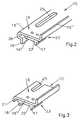
- the adapter piece 23 can be of limited length, such as it is shown in Figures 2 to 4. But it can also over run through the entire length of the L-profile, if one Stiffening should be useful, for example stiffening of the frame spar 11 in the area of the rebate 40 because the stiffening profile 30 was not used.
- the L-profile 16 is made of steel, for example.
- the L-profile 16 is produced by rolling, ie with Help of a process from a flat strip material the desired profile shape is produced by successively deformations occurring with differently trained Roll sets an edge of the strip material to the leg 16 '' deform.
- the bent spar cover edge can do the same 21 are manufactured.
- the entire L-profile is 16 to its final form in a single pass rolled. However, several workstations can also be used for this be used. That will be particularly necessary if the profiling of the L-profile 16 is more complicated.
- Figure 2 shows an L-profile 16, which on its Edge 16 '' 'on the inside of the room with an S-like shape 36 is provided as part of a mounting rib 18 has.
- This rolled-up fastening rib 18 is in Combination with the fastening rib 17 of the adapter piece 23 used to fix the L-profile 16 to the frame spar 11, for example by jamming.
- the entire length of the L-profile continuous fastening rib 18 stabilized the L-profile is considerably better than that through the length distributed adapter pieces 23 could be achieved. It is therefore strive for the L-profile 16 overall by rolling is made in one piece from strip material.
- Fig. 5 shows an L-profile 16 or a rebate cover strip 10, which is made entirely of rolls of strip material is.
- the mounting rib 17 is by doubling the Band material made, like the leg, by the way 16 ''.
- this fold cover strip 10 has the special feature on that their L-profile by double the strip material is made. So the thickness 37 of the leg Being able to manufacture 16 'became a strip material that was half as thick rolled into the shape shown, in all lengths there are two layers of this strip material. This is also recognizable in the area of the fastening rib 18 where the end edges of the original strip material side by side lie.
- the folding cover strip 10 is provided with recesses 25, which serve to engage drive rod components, for example the engagement of locking bolts.
- One in one Recess 25 engaging locking bolt causes the The door leaf is not opened or the frame rail 13 is not pivoted can be.
- a corresponding in the frame spar 11 There is a recess for installing the lock pocket have to be.
- the closing pocket 26 has a collar 27 on the fold side formed, the 38 forming the recess 25 edges Leg 16 'overlaps and covered. Below the Leg 16 'is the closure pocket with a longitudinal recess 28 provided so that a positive attachment is used here can be with which the closure pocket 26 on the leg 16 'is attached.
- Fig. 7 shows a U-shaped bracket on the left 29, which underneath the leg 16 ′ into the longitudinal recess 28 can be inserted with pressure, so that a tight fit is achieved. This installation is done before the rebate cover strip 10 is assembled with the frame spar 11 becomes.
Landscapes
- Engineering & Computer Science (AREA)
- Civil Engineering (AREA)
- Structural Engineering (AREA)
- Mechanical Engineering (AREA)
- Joining Of Corner Units Of Frames Or Wings (AREA)
- Seal Device For Vehicle (AREA)
- Laminated Bodies (AREA)
Abstract
Description
- Fig.1
- einen Querschnitt durch ein Hohlkammerprofil eines Rahmenholms, an dessen Seitenfläche eine Falzabdeckleiste angeordnet ist,
- Fig.2-4
- jeweils perspektivische Darstellungen von Stücken einer Falzabdeckleiste mit einem jeweils zugehörigen Adapterstück,
- Fig.5
- eine Darstellung einer einstückig gerollten Falzabdeckleiste mit Befestigungsrippen,
- Fig.6
- eine Falzabdeckleiste mit eingebauter Schließtasche in geschnittener Darstellung und
- Fig.7
- die komplette Schließtasche der Fig.6 in perspektivischer Darstellung mit einer in Zusammenbaubereitschaftsstellung angeordneten T-förmigen Klammer.
Claims (16)
- Falzabdeckleiste (10) eines Tür- oder Fensterrahmens, insbesondere eines Kunststoffrahmens, der profilierte hohle Rahmenholme (11) mit einer Seitenfläche (12) aufweist, die einem benachbarten Rahmenholm (13) eines zweiten Rahmens zugewendet ist und von der ein einen Falzraum (14) zwischen beiden Rahmen abdeckender Überschlag (15) vorspringt, wobei die Abdeckleiste (10) die Seitenfläche (12) des Rahmenholms (11) sowie die daran angrenzende Überschlagfläche (15') zumindest je zum Teil mittels L-Profils (16) abdeckt und an der Seitenfläche (12) mit gegenseitig ineinandergreifenden Befestigungsrippen (17,18) und -rillen (19) festgelegt ist, dadurch gekennzeichnet, daß das L-Profil (16) der Falzabdeckleiste (10) durch Rollen aus Bandwerkstoff einstückig hergestellt ist.
- Falzabdeckleiste nach Anspruch 1, dadurch gekennzeichnet, daß sie mindestens eine durch Rollen aus dem Bandwerkstoff einstückig mit dem L-Profil (16) hergestellte Befestigungsrippe (17,18) oder -rille (19) aufweist.
- Falzabdeckleiste nach Anspruch 1 oder 2, dadurch gekennzeichnet, daß eine Befestigungsrippe (18) eine durch Rollen abgebogene Endkante des L-Profils (16) ist.
- Falzabdeckleiste nach einem oder mehreren der Ansprüche 1 bis 3, dadurch gekennzeichnet, daß eine Befestigungsrippe (17,18) eine durch Rollen hergestellte Verdoppelung des Bandwerkstoffs ist.
- Falzabdeckleiste nach einem oder mehreren der Ansprüche 1 bis 4, dadurch gekennzeichnet, daß das L-Profil (16) der Falzabdeckleiste (10) durch verdoppelndes Rollen des Bandwerkstoffs mit dementsprechend doppelter Bandwerkstoffdicke hergestellt ist.
- Falzabdeckleiste nach einem oder mehreren der Ansprüche 1 bis 5, dadurch gekennzeichnet, daß sie mit zwei einander parallel vorspringenden Befestigungsrippen (17,18) aus einem einzigen Streifen Bandwerkstoffs hergestellt ist.
- Falzabdeckleiste nach einem oder mehreren der Ansprüche 1 bis 6, dadurch gekennzeichnet, daß das L-Profil (16) an seinem die Seitenfläche (12) des Rahmenholms (11) abdeckenden Schenkel (16') eine einstückig angerollte abgebogene Holmabdeckkante (21) aufweist.
- Falzabdeckleiste, insbesondere nach einem oder mehreren der Ansprüche 1 bis 7, dadurch gekennzeichnet, daß an dem bedarfsweise gerollten L-Profil (16) ein der Seitenfläche (12) des Rahmenholms (11) benachbartes Adapterstück (23) angebracht ist, das mindestens eine Befestigungsrippe (17,18) oder -rille (19) hat.
- Falzabdeckleiste nach einem oder mehreren der Ansprüche 1 bis 8, dadurch gekennzeichnet, daß das Adapterstück (23) mit einer rahmenholmseitig flach an dem L-Profil (16) anliegenden Befestigungsplatte (22) versehen ist.
- Falzabdeckleiste nach einem oder mehreren der Ansprüche 1 bis 9, dadurch gekennzeichnet, daß das Adapterstück (23) in Längsrichtung des L-Profils (16) mit einer über dessen Ende vorspringenden Verbindungslänge (24) ausgebildet ist.
- Falzabdeckleiste nach einem oder mehreren der Ansprüche 1 bis 10, dadurch gekennzeichnet, daß die bedarfsweise angerollten Befestigungsrippen (17,18) oder -rillen (19) in Abstimmung auf Befestigungsrillen- oder rippen eines einem Rahmensystem entsprechenden Rahmenholms (11) am L-Profil (16) angeordnet sind.
- Falzabdeckleiste nach einem oder mehreren der Ansprüche 1 bis 11, dadurch gekennzeichnet, daß das L-Profil (16) in seinem die Seitenfläche (12) des Rahmenholms abdeckenden Schenkel (16') eine Ausnehmung (25) hat, in die eine Schließtasche (26) eingebaut ist.
- Falzabdeckleiste nach einem oder mehreren der Ansprüche 1 bis 12, dadurch gekennzeichnet, daß die Schließtasche (26) das L-Profil (16) falzseitig mit einem Kragen (27) übergreift und rahmenholmseitig dicht unter dem L-Profil (16) befestigt ist.
- Falzabdeckleiste nach einem oder mehreren der Ansprüche 1 bis 13, dadurch gekennzeichnet, daß die Schließtasche (26) an dem L-Profil (16) mit einem vertikal formschlüssigen Anbauteil befestigt ist.
- Falzabdeckleiste nach einem oder mehreren der Ansprüche 1 bis 14, dadurch gekennzeichnet, daß das Anbauteil eine in eine Längsausnehmung (28) formschlüssig eingeschobene U-förmige Klammer (29) ist.
- Falzabdeckleiste nach einem oder mehreren der Ansprüche 1 bis 15, dadurch gekennzeichnet, daß das L-Profil (16) aus Stahl besteht.
Applications Claiming Priority (2)
| Application Number | Priority Date | Filing Date | Title |
|---|---|---|---|
| DE19809691 | 1998-03-06 | ||
| DE1998109691 DE19809691A1 (de) | 1998-03-06 | 1998-03-06 | Falzabdeckleiste eines Tür- oder Fensterrahmens |
Publications (2)
| Publication Number | Publication Date |
|---|---|
| EP0940548A2 true EP0940548A2 (de) | 1999-09-08 |
| EP0940548A3 EP0940548A3 (de) | 2000-06-14 |
Family
ID=7859992
Family Applications (1)
| Application Number | Title | Priority Date | Filing Date |
|---|---|---|---|
| EP99103172A Withdrawn EP0940548A3 (de) | 1998-03-06 | 1999-02-18 | Falzabdeckleiste eines Tür- oder Fensterrahmens |
Country Status (2)
| Country | Link |
|---|---|
| EP (1) | EP0940548A3 (de) |
| DE (1) | DE19809691A1 (de) |
Cited By (2)
| Publication number | Priority date | Publication date | Assignee | Title |
|---|---|---|---|---|
| WO2010006626A1 (de) * | 2008-07-17 | 2010-01-21 | Sylid Systemlogistik Und Industriedienstleistung Gmbh | Putzleiste |
| CN108590467A (zh) * | 2018-04-28 | 2018-09-28 | 温州博旺联科建筑工程有限公司 | 一种易拆卸的紧急逃生门 |
Families Citing this family (1)
| Publication number | Priority date | Publication date | Assignee | Title |
|---|---|---|---|---|
| US6391434B1 (en) | 1999-05-06 | 2002-05-21 | General Electric Company | Composite scintillator material and method of manufacture |
Family Cites Families (14)
| Publication number | Priority date | Publication date | Assignee | Title |
|---|---|---|---|---|
| DE7139259U (de) * | Wohnhaas K | Halterung für in eine Wandöffnung einzufügende Rahmen | ||
| DE7022331U (de) * | 1971-11-18 | Dyna Plastik Werk Gmbh | Vorrichtung zum Verriegeln eines Flügels mit einem Rahmen | |
| DE2143698A1 (de) * | 1971-09-01 | 1973-07-26 | Dynamit Nobel Ag | Stranggepresste profile, vorzugsweise aus einem thermoplastischen kunststoff, fuer blendrahmen und fluegelrahmen von schiebefenstern, schiebetueren o.dgl |
| DE2927728A1 (de) * | 1979-07-10 | 1981-01-29 | Kabel Metallwerke Ghh | Fenster |
| DE8709264U1 (de) * | 1987-07-04 | 1988-11-10 | Niemann, Hans Dieter, 5014 Kerpen | Kunststoffrahmen für Fenster, Türen od.dgl. |
| DE8804031U1 (de) * | 1988-03-25 | 1988-07-14 | Schüring GmbH & Co Fenstertechnologie KG, 5000 Köln | U-Stulpe für Kantengetriebe |
| DE8913501U1 (de) * | 1989-11-15 | 1990-01-04 | König, Richard, 3180 Wolfsburg | Kunststoffprofil als Flügelrahmen für Fenster o.dgl. mit symetrischem Profilquerschnitt |
| DE4011607C2 (de) * | 1990-04-10 | 1995-03-30 | Sommer Metallbau Stahlbau Gmbh | Brandschutzdichtung |
| DE9301598U1 (de) * | 1993-02-05 | 1994-06-01 | Niemann, Hans Dieter, 50169 Kerpen | Rahmen für Fenster, Türen o.dgl., insbesondere Kunststoffrahmen |
| DE9318529U1 (de) * | 1993-12-03 | 1994-03-10 | PaX GmbH, 55218 Ingelheim | Aufbruchsicherung an Fenstern, Türen o.dgl. |
| DE9406202U1 (de) * | 1994-04-14 | 1994-07-14 | PaX GmbH, 55218 Ingelheim | Fensterflügelrahmen-Hohlprofil und daraus bestehender Doppelflügel-Fensterrahmen |
| DE29500148U1 (de) * | 1995-01-05 | 1996-05-09 | Niemann, Hans Dieter, 50169 Kerpen | Rahmenprofil für Fenster oder Türen |
| GB2300212B (en) * | 1995-04-26 | 1998-08-05 | Equator Wheels & Sections Ltd | Reinforcement sections |
| DE29800306U1 (de) * | 1998-01-10 | 1998-05-14 | KBE Vertriebsgesellschaft für Kunststoffprodukte GmbH, 66763 Dillingen | Beschlag für einen Flügelrahmen von Fenstern oder Türen |
-
1998
- 1998-03-06 DE DE1998109691 patent/DE19809691A1/de not_active Withdrawn
-
1999
- 1999-02-18 EP EP99103172A patent/EP0940548A3/de not_active Withdrawn
Cited By (3)
| Publication number | Priority date | Publication date | Assignee | Title |
|---|---|---|---|---|
| WO2010006626A1 (de) * | 2008-07-17 | 2010-01-21 | Sylid Systemlogistik Und Industriedienstleistung Gmbh | Putzleiste |
| CN108590467A (zh) * | 2018-04-28 | 2018-09-28 | 温州博旺联科建筑工程有限公司 | 一种易拆卸的紧急逃生门 |
| CN108590467B (zh) * | 2018-04-28 | 2019-05-24 | 温州博旺联科建筑工程有限公司 | 一种易拆卸的紧急逃生门 |
Also Published As
| Publication number | Publication date |
|---|---|
| EP0940548A3 (de) | 2000-06-14 |
| DE19809691A1 (de) | 1999-09-09 |
Similar Documents
| Publication | Publication Date | Title |
|---|---|---|
| EP1555376A1 (de) | Verbundprofilanordnung | |
| EP0524447A1 (de) | Fenstereinfassrahmen, insbesondere für Fahrzeuge | |
| EP0786576B1 (de) | Elastische Strangdichtung für Fenster, Türen oder dgl. | |
| EP0298354B1 (de) | Kunststoffrahmen für Fenster, Türen od. dgl. | |
| EP0995001B1 (de) | Anordnung eines beschlagteils an einem rahmen | |
| EP0740039A1 (de) | Fenster oder Tür mit Flügel und Blendrahmen und mit einem Treibstangenbeschlag sowie Verfahren zur Ausstattung der Flügel mit diesem Treibstangenbeschlag | |
| DE9419959U1 (de) | Vorrichtung zum Verbinden von Kunststoffprofilen | |
| EP4573255A1 (de) | Profilanordnung eines fensters oder einer tür mit einem flügelprofil, insbesondere einem schiebeflügelprofil | |
| DE2715238A1 (de) | Fenster- oder tuerrahmen | |
| DE4439234C1 (de) | Fenster, insbesondere aus Kunststoff, bestehend aus Flügelrahmen-Hohlprofilen und Blendrahmen | |
| EP0940548A2 (de) | Falzabdeckleiste eines Tür- oder Fensterrahmens | |
| DE69827182T2 (de) | Mobile Unterkunft mit einem zu öffnenden oder nicht zu öffnenden Fenster | |
| DE2514694C3 (de) | Hölzerner Blendrahmen für Fenster oder Türen mit einem Abdeckprofil aus wetterfestem Material | |
| DE69512261T2 (de) | Diebstahlsicherer profilsatz und profilstreifen hierfür | |
| EP0792992B1 (de) | Nachrüstzarge für Türen | |
| DE3125883C2 (de) | Gehrungseckverbindung für aus Kunststoff- oder kombinierten Metall-Kunststoff-Profilstäben zusammengesetzte Hohlprofil-Rahmen, insbesondere Fenster- oder Türrahmen | |
| DE8712982U1 (de) | Rolladen oder Rolltor | |
| EP1676970A2 (de) | Befestigung eines Beschlagteils | |
| DE202004000817U1 (de) | Rahmenkörper aus einem hohlen, stranggepreßten Kunststoffprofil für Fenster und Türen | |
| DE29903324U1 (de) | Rahmen eines Fensters, einer Klappe oder einer Tür an Wohnwagen, Wohnmobilen oder sonstigen Fahrzeugen | |
| EP2754803A2 (de) | Riegelstangenbeschlag für ein Fenster oder eine Tür | |
| DE2457940A1 (de) | Wandstaerkeneinstellbare tuerzarge | |
| EP0721041B1 (de) | Stangenförmiges Beschlagteil für Treibstangenbeschläge und damit versehener Treibstangenbeschlag sowie Halbzeug und Verfahren zur Herstellung des Beschlagteils | |
| EP1031692B1 (de) | Schliessplatte für Verschlüsse an Gebäudefenstern und/oder Gebäudetüren | |
| DE102011008765A1 (de) | Profilanordnung, Rahmen und Rahmenanordnung |
Legal Events
| Date | Code | Title | Description |
|---|---|---|---|
| PUAI | Public reference made under article 153(3) epc to a published international application that has entered the european phase |
Free format text: ORIGINAL CODE: 0009012 |
|
| AK | Designated contracting states |
Kind code of ref document: A2 Designated state(s): AT CH DE LI NL |
|
| AX | Request for extension of the european patent |
Free format text: AL;LT;LV;MK;RO;SI |
|
| PUAL | Search report despatched |
Free format text: ORIGINAL CODE: 0009013 |
|
| AK | Designated contracting states |
Kind code of ref document: A3 Designated state(s): AT BE CH CY DE DK ES FI FR GB GR IE IT LI LU MC NL PT SE |
|
| AX | Request for extension of the european patent |
Free format text: AL;LT;LV;MK;RO;SI |
|
| 17P | Request for examination filed |
Effective date: 20001006 |
|
| AKX | Designation fees paid |
Free format text: AT CH DE LI NL |
|
| STAA | Information on the status of an ep patent application or granted ep patent |
Free format text: STATUS: THE APPLICATION IS DEEMED TO BE WITHDRAWN |
|
| 18D | Application deemed to be withdrawn |
Effective date: 20031002 |