EP0940549A2 - Pièce d'assemblage d'angle pour relier par soudage deux profilés creux - Google Patents
Pièce d'assemblage d'angle pour relier par soudage deux profilés creux Download PDFInfo
- Publication number
- EP0940549A2 EP0940549A2 EP99101004A EP99101004A EP0940549A2 EP 0940549 A2 EP0940549 A2 EP 0940549A2 EP 99101004 A EP99101004 A EP 99101004A EP 99101004 A EP99101004 A EP 99101004A EP 0940549 A2 EP0940549 A2 EP 0940549A2
- Authority
- EP
- European Patent Office
- Prior art keywords
- corner connector
- expansion element
- connector according
- end sections
- run
- Prior art date
- Legal status (The legal status is an assumption and is not a legal conclusion. Google has not performed a legal analysis and makes no representation as to the accuracy of the status listed.)
- Granted
Links
Images


Classifications
-
- E—FIXED CONSTRUCTIONS
- E06—DOORS, WINDOWS, SHUTTERS, OR ROLLER BLINDS IN GENERAL; LADDERS
- E06B—FIXED OR MOVABLE CLOSURES FOR OPENINGS IN BUILDINGS, VEHICLES, FENCES OR LIKE ENCLOSURES IN GENERAL, e.g. DOORS, WINDOWS, BLINDS, GATES
- E06B3/00—Window sashes, door leaves, or like elements for closing wall or like openings; Layout of fixed or moving closures, e.g. windows in wall or like openings; Features of rigidly-mounted outer frames relating to the mounting of wing frames
- E06B3/96—Corner joints or edge joints for windows, doors, or the like frames or wings
- E06B3/964—Corner joints or edge joints for windows, doors, or the like frames or wings using separate connection pieces, e.g. T-connection pieces
- E06B3/968—Corner joints or edge joints for windows, doors, or the like frames or wings using separate connection pieces, e.g. T-connection pieces characterised by the way the connecting pieces are fixed in or on the frame members
- E06B3/972—Corner joints or edge joints for windows, doors, or the like frames or wings using separate connection pieces, e.g. T-connection pieces characterised by the way the connecting pieces are fixed in or on the frame members by increasing the cross-section of the connecting pieces, e.g. by expanding the connecting pieces with wedges
- E06B3/9725—Mitre joints
-
- E—FIXED CONSTRUCTIONS
- E06—DOORS, WINDOWS, SHUTTERS, OR ROLLER BLINDS IN GENERAL; LADDERS
- E06B—FIXED OR MOVABLE CLOSURES FOR OPENINGS IN BUILDINGS, VEHICLES, FENCES OR LIKE ENCLOSURES IN GENERAL, e.g. DOORS, WINDOWS, BLINDS, GATES
- E06B3/00—Window sashes, door leaves, or like elements for closing wall or like openings; Layout of fixed or moving closures, e.g. windows in wall or like openings; Features of rigidly-mounted outer frames relating to the mounting of wing frames
- E06B3/96—Corner joints or edge joints for windows, doors, or the like frames or wings
- E06B3/9604—Welded or soldered joints
- E06B3/9608—Mitre joints
Definitions
- the invention relates to a welding corner connector of hollow chamber profiles, with one on the outside of a hollow chamber adapted insert body, the one at a first end has weldable connection surface and that at a second end is formed with cross-expandable end sections, and with one between the end sections on this when actuated spreading expansion element.
- a welding corner connector with the aforementioned features is known from EP-A-0 288 756.
- the well-known expansion element is an expansion dowel, an expansion wedge or the like, which either by tightening a screw and / or by moving it axially achieved the spread that is necessary for itself the welding corner connector sticks in the hollow chamber profile.
- the Extent of the axial fixation required Axial movement is dependent on the tolerances of the involved components differently. There may therefore be irregularities when fixing the corner connector axially different parts of the hollow chamber profile come which may affect connection security.
- the invention is therefore based on the object Welding corner connector with the characteristics mentioned above to improve that improved, especially the welded corner connector sits more securely in the hollow chamber profile results.
- the expansion element is exclusive adjustable and only a rotary adjustment of the Spreading element leads to the desired spreading of the end sections of the insert body.
- the welding corner connector trained such that an unintended Turning back of the expansion element is excluded. It is as a result not possible that the clamp of the welded corner connector is unwanted loosened in the hollow chamber profile.
- a rotary adjustment of the expansion element Advantage that the jamming takes place on a short angle of rotation can. So there are no significant rotary adjustments required, for example as a result of one used for the spread flat screw thread to the expansion element to fix. In conjunction with a torque wrench can be ensured that a secure clamping under structurally predetermined conditions of a single Axial position is reached.
- the welding corner connector consists of only two components. These components are structurally coordinated so that the actuation of only the expansion element is sufficient, So a single element to fix the weld corner connector to achieve in the hollow chamber profile.
- the stake another component causing an adjustment, for example a screw is avoided.
- a use of metal can be superfluous. This can also lead to weight loss contribute.
- the welding corner connector can be designed such that the expansion element with the insert body in a predetermined Axial position is locked rotatably.
- the latch causes the expansion element and the insert body always take the same axial relative position to each other, so that the spreading element is always spreading in the same axial position acts on the end portions.
- the assembly of the Spreading element and the plug-in body takes place via a advantageous latching in terms of assembly.
- the welded corner connector is expediently designed in such a way that that the locking of the expansion element with a longitudinally slotted pin is made with a pin head engages behind a collar of the plug-in body.
- the assembly the expansion element and the insertion body takes place by simply pushing them together until they snap into place. Further Measures to assemble the from only two components existing welded corner connectors are not required.
- the pin on the connection surface side one, if necessary, arranged with an interchangeable insert has non-circular actuation recess.
- Non-circular actuation recesses are special for achieving rotary adjustments suitable. They also allow significant operating forces to transfer, namely with accordingly out of round Operating tools. It is particularly advantageous if the pin is provided with an interchangeable insert, so that for example an internal hexagon recess through an internal square recess can be replaced to different Operating tools and / or operating forces to be able to.
- the welding corner connector In order to save weight, it is advantageous to Design the welding corner connector so that the insert body at least in the area of its end sections and / or that Spreading element at least in the area of its actuating arms is / are thin-walled hollow. Even with this configuration the corner connector is the required strength and to achieve stiffness and in particular the required deformations of the cross-expandable end sections facilitated.
- a stiffening of the expansion element can be achieved if the weld corner connector is designed so that the expansion element between the pin and the actuating arms Has stiffening ribs. Which is between the tenon and stiffening ribs each extending the operating arms avoid an otherwise more solid and more material Training of the expansion element and can also in The design of the expansion element as a hollow body be used.
- the weld corner connector is expediently used on several Set the hollow chamber profile fixed or spread.
- the end sections are evenly over 360 ° distributed, as well as the operating arms, so that a clamping action in four mutually accordingly results in different directions. That means one optimal jamming of the welding corner connector with comparative low design effort.
- the welding corner connector can be in the area of its end sections be specially adapted. It is particularly advantageous if provide the end sections of the insert body with ramp surfaces are those with increasing angle of rotation of the actuating arms of the expansion element increasingly protrude into their outer circumferential path. With the contact surfaces, the contact pressure can be between the end sections and the hollow chamber profile for a predetermined expansion element in relation to the actuation angle of rotation be determined.
- the run-up surfaces are expedient trained so that the largest possible and necessary Clamping force between the end sections and the hollow chamber profiles for maximum tolerances of the components involved is reached at the end of the ramp area.
- the ramp surfaces have thin walls protrude from the end portions and with their end edges the end sections are supported.
- the ramp surfaces can be shaped according to the clamping conditions without doing so to increase the mass of the weld corner connector over the fee.
- the end support of the ramp surfaces ensures that required stabilization and can be trained that the clamping forces introduced in the desired direction act on the end sections.
- the welding corner connector can be designed so that the run-up surfaces of a rectangular insert body each are assigned to one of the side surfaces, the narrow Ramp surfaces assigned to side surfaces each by one longer actuating arm matched to half the long side and the ramp surfaces assigned to the wide side surfaces each from one to the half narrow side shorter actuating arm are applied.
- the expansion element remains with its axis coaxial or axially parallel to Hollow chamber profile or to the insert body. A tilt of the Spreader element is avoided and resulting impairments the clamping of the end sections in the hollow chamber profile do not occur.
- the welding corner connector in such a way that that the ramp faces towards the pad are inclined towards the connector axis. With the help of inclination the ramp surfaces can be achieved that the expansion element can be inserted without disabilities and without play sits in the insert body by the spring action of the end portions is used for this.
- ends of the operating arms are spherical, act these ends and the run-up surfaces also in the case of production-related Tolerances in the shape without abrasion are flawless together.
- the expansion element is not unintentionally turns back. If this is the case with the given Forming the expansion element and insert body or ramp surfaces cannot be easily achieved, it is advisable the weld corner connector so that at least a ramp surface and / or at least one actuating arm Provide friction-increasing agents on the contact surface is.
- the friction-increasing means can then be designed in this way be that an unintentional turning back with certainty is avoided.
- Such a prevention is done in a constructively simple manner of unwanted twisting achieved by a ramp surface and / or the actuating arm assigned to this ribbed, grooved, knurled, toothed on the contact surface or the like. is / are.
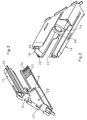
- the insertion body 11 has a first end 11 'on which a weldable pad 13 is present.
- the pad 13 is in the usual way with material cams 13 ' occupied, the welding of adjacent pads 13 serve two welding corner connectors 10.
- the welding corner connectors 10 are for welding two at right angles to each other Hollow chamber profiles at 45 ° against the connector axis 24 arranged inclined.
- the insertion body 11 is essentially with the rest rectangular cross section.
- On the rectangular one second end 11 ′′ of the plug body 11 are expandable end sections 14 available.
- Each end section 14 is in cross section angular, since the plug-in body 11 over its entire length Length from the pad 13 at the first end 11 'to to the second end 11 '' has continuous slots 26.
- These slots 26 run on narrow side surfaces 22 of the rectangular insert body 11 along the entire length constant width and have in the wide side surfaces 23 in the area of the second end 11 '' extensions 25 'for the purpose of saving material and coordinating the Suspension properties of the end sections 14. Accordingly are the angular end portions 14 with in cross section unequal legs.
- the end sections 14 have run-on surfaces 20, 21.
- Each two diametrically opposed ramp surfaces 20 and 21 are of identical design. You in Fig.7 with r designated distance decreases, based on increasing Angle of rotation counterclockwise of the display. Consequently protrude the run-up surfaces 20,21 each with growing Angle of rotation counterclockwise or as it grows Angle of rotation of the expansion element 12 in the counterclockwise direction in the Outer circumferential path of the expansion element 12 or in the outer circumferential path of actuating arms 18, 18 'of this expansion element 12 in.
- the ramp surfaces 20, 21 are each made of thin walls formed, which protrude from the end portions 14. In order to their end edges are able to absorb larger support forces 20 ', 21' each connected to the end sections 14.
- the Ramp surfaces 20 directly abut in their arc shape End edge sections 14, while the end edges 21 'with connecting webs 27 are supported on the end sections 14, and in the corner angle area of the angled end sections 14.
- Fig. 7 shows that the run-up surfaces 20, 21 in Inclined towards the connection surface 13 of the connector axis 24 are.
- the resulting areas, e.g. 28, lighten the assembly of the expansion element 12 and can with appropriate extension in the longitudinal direction cause the expansion element 12 using the elasticity of the End sections 14 tightly stuck in the insert body 11.
- FIG. 1 to 3 show that the pad 13 of an actuating recess 29 is broken.
- This recess 29 ends with a diameter reducing Ring collar 16, the installation or the axial storage of the Spreading element 12 is used.
- the collar 16 engages behind Pin head 15 'of a pin 15 of the expansion element.
- the cone 15 is slit longitudinally and its pin head 15 'is with an outer diameter that is slightly larger, than the inside diameter of the ring collar 16. As a result it is possible to remove the pin 15 due to its slitting from the second End 11 '' through the collar 16 until one Latching occurs.
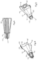
- the expansion element 12 has on its opposite the pin 15 End four actuating arms 18, 18 '. Every operating arm 18, 18 'is assigned to one of the run-up surfaces 20, 21. Starting from the pin 15 or from a pin collar 30 there are stiffening ribs 19, the expansion element 12 otherwise to a body with a closed outer shell is trained and a inherent rigidity caused thereby having. Figures 4.5 illustrate this in perspective Presentation.
- the actuating arms 18, 18 ' ach jump differently far radially from the connector axis 24.
- the operating arms 18 are longer than the actuating arms 18 '. It takes place an assignment of the actuating arms 18 to the narrow Side surfaces 22 of the rectangular insert body 11 and Actuator arms 18 'to the wider side surfaces 23. Die
- the length of the actuating arms 18 is half the long side matched while the length of the shorter actuating arms 18 'is matched to half the narrow side.
- the outer ends of the operating arms 18, 18 ' are each spherical so that there is a correspondingly reduced resistance Moving the ends of the actuating arms 18, 18 ' results on the run-up surfaces 20, 21.
- the expansion body 12 must be designed so that it after a twisting maintains its twisted position. For this are on the end sections 14 and on the actuating arms 18 friction-increasing Means available.
- A is shown in FIG Toothing 31, into which a toothing 32, cf. Fig. 4 intervenes.
- the teeth 31, 32 are each designed such that they only comparatively a twisting of the expansion element 12 oppose little resistance. It will achieved, for example, by twisting each other sliding flanks of the toothing more inclined or be spherical compared to the tooth flanks, which oppose a turning back of the expansion element 12.
- the teeth are accordingly barb-shaped educated.
- the expansion element 12 is rotated by a key, not shown, in a non-circular actuation recess 17 of the expansion element 12 or of the pin 15 is inserted.
- Fig.6 shows that this actuation recess 17 practically over the entire length of the expansion element 12 passes through, so that a very safe deep and the material of the expansion element is only slightly stressful Intervention with the key results. Above all, it can Operation by deep key engagement directly in the radial area of the actuating arms 18, 18 'take place for what Stability of the clamp connection and its metrological determination with a torque wrench is an advantage.
- the non-circular actuation recess is as a hexagon recess shown.
- the advantages of the welded corner connector already described above 10 is to be added that he also with a hollow chamber-like design, i.e. with comparatively thin Walls of its insert body 11, a considerable torsional rigidity can have.
- the two components of the weld corner connector 10 form an all-plastic corner. Screws or other metal parts that are otherwise required for fastening, can be avoided so that e.g. in the case of lock milling or cutouts in the corner area no longer disturb. Since the corner connector can only be made of plastic can, is the claim to the simplest possible recyclability perfectly fulfilled. It is not necessary to have different Separate materials separately. This is particularly the case if the material of the welded corner connector is the same as the material is the hollow chamber profiles that connect to each other are.
- the shape of the spreading arms and the Ramparts are achieved that are targeted Spreading is possible in all directions, so that the Butt weld connectors also in such hollow chamber profiles or Tubes can be used, one of the illustrated Cross-section have a different shape.
- the spread is consequently possible in all directions and it can do so optimization of the torsional strength can be achieved.
Landscapes
- Engineering & Computer Science (AREA)
- Civil Engineering (AREA)
- Structural Engineering (AREA)
- Standing Axle, Rod, Or Tube Structures Coupled By Welding, Adhesion, Or Deposition (AREA)
- Butt Welding And Welding Of Specific Article (AREA)
- Body Structure For Vehicles (AREA)
- Mutual Connection Of Rods And Tubes (AREA)
- Joining Of Corner Units Of Frames Or Wings (AREA)
- Lining Or Joining Of Plastics Or The Like (AREA)
- Joining Of Building Structures In Genera (AREA)
Applications Claiming Priority (2)
| Application Number | Priority Date | Filing Date | Title |
|---|---|---|---|
| DE19809482 | 1998-03-06 | ||
| DE19809482A DE19809482C2 (de) | 1998-03-06 | 1998-03-06 | Schweißeckverbinder von Hohlkammerprofilen |
Publications (3)
| Publication Number | Publication Date |
|---|---|
| EP0940549A2 true EP0940549A2 (fr) | 1999-09-08 |
| EP0940549A3 EP0940549A3 (fr) | 2000-10-04 |
| EP0940549B1 EP0940549B1 (fr) | 2005-06-15 |
Family
ID=7859840
Family Applications (1)
| Application Number | Title | Priority Date | Filing Date |
|---|---|---|---|
| EP99101004A Expired - Lifetime EP0940549B1 (fr) | 1998-03-06 | 1999-01-18 | Pièce d'assemblage d'angle pour relier par soudage deux profilés creux |
Country Status (4)
| Country | Link |
|---|---|
| EP (1) | EP0940549B1 (fr) |
| AT (1) | ATE298036T1 (fr) |
| DE (2) | DE19809482C2 (fr) |
| PL (1) | PL196559B1 (fr) |
Cited By (1)
| Publication number | Priority date | Publication date | Assignee | Title |
|---|---|---|---|---|
| EP1054130A3 (fr) * | 1999-05-18 | 2002-08-14 | Hans Dieter Grotefeld | Procédé pour fixer un joint d'angle dans un profilé creux d'une porte ou fenêtre et joint d'angle et outil pour réaliser ce procédé |
Family Cites Families (11)
| Publication number | Priority date | Publication date | Assignee | Title |
|---|---|---|---|---|
| DD49376A (fr) * | ||||
| US4149352A (en) * | 1977-06-20 | 1979-04-17 | Allen David L | Modular panel apparatus |
| DE2755917A1 (de) * | 1977-12-15 | 1979-06-21 | Erwin Bergmann | Metall-profilleiste mit thermischer unterbrechung, insbesondere fuer fenster, tueren oder dergleichen |
| AU563550B2 (en) * | 1983-12-21 | 1987-07-16 | Warr, M.G. | Picture framing system |
| GB8501297D0 (en) * | 1985-01-18 | 1985-02-20 | Hara J B O | Joint for connecting tube/rod members |
| DE3745029C2 (de) * | 1987-04-13 | 1996-01-04 | Huels Troisdorf | Eckverbinder sowie Verfahren zum Verbinden zweier auf Gehrung geschnittener Hohlkammerprofile |
| FR2618862B1 (fr) * | 1987-07-27 | 1989-10-27 | Hassid Jean Pierre | Dispositif d'assemblage de tubes ou analogues comportant un logement en creux de forme cylindrique ou analogue |
| DE8809311U1 (de) * | 1988-07-21 | 1988-09-01 | Grotefeld, Hans Dieter, 4970 Bad Oeynhausen | Eckverbinder aus Kunststoff |
| DE9014643U1 (de) * | 1990-10-23 | 1991-01-24 | Niemann, Hans Dieter, 5014 Kerpen | Eckschweißverbinder zum Verbinden zweier auf Gehrung geschnittener Hohlkammerprofile |
| DE9301619U1 (de) * | 1993-02-05 | 1994-03-10 | Cera Handelsgesellschaft Mbh, 87640 Biessenhofen | Spreizbarer Sprossenverbinder |
| DE19734875C2 (de) * | 1997-08-12 | 2003-02-06 | Peter Willrich | Verbindungselement für ein Hohlteil mit einem weiteren Teil im Tür- und Fensterbau |
-
1998
- 1998-03-06 DE DE19809482A patent/DE19809482C2/de not_active Expired - Fee Related
-
1999
- 1999-01-18 EP EP99101004A patent/EP0940549B1/fr not_active Expired - Lifetime
- 1999-01-18 DE DE59912173T patent/DE59912173D1/de not_active Expired - Lifetime
- 1999-01-18 AT AT99101004T patent/ATE298036T1/de active
- 1999-02-26 PL PL331662A patent/PL196559B1/pl unknown
Cited By (1)
| Publication number | Priority date | Publication date | Assignee | Title |
|---|---|---|---|---|
| EP1054130A3 (fr) * | 1999-05-18 | 2002-08-14 | Hans Dieter Grotefeld | Procédé pour fixer un joint d'angle dans un profilé creux d'une porte ou fenêtre et joint d'angle et outil pour réaliser ce procédé |
Also Published As
| Publication number | Publication date |
|---|---|
| DE59912173D1 (de) | 2005-07-21 |
| DE19809482C2 (de) | 2000-05-31 |
| DE19809482A1 (de) | 1999-09-16 |
| ATE298036T1 (de) | 2005-07-15 |
| EP0940549B1 (fr) | 2005-06-15 |
| PL331662A1 (en) | 1999-09-13 |
| EP0940549A3 (fr) | 2000-10-04 |
| PL196559B1 (pl) | 2008-01-31 |
Similar Documents
| Publication | Publication Date | Title |
|---|---|---|
| DE4401746C2 (de) | T Mutter | |
| DE3625691C2 (fr) | ||
| EP0691478B1 (fr) | Dispositif de fixation pour une ferrure ayant un alésage, en particulier pour un élément de charnière | |
| DE29522207U1 (de) | Bohrfutter | |
| EP3256089B1 (fr) | Mâchoire de serrage destinée à être montée sur une glissière d'une table d'opération | |
| DE20023454U1 (de) | Rastbeschlag für einen Fahrzeugsitz | |
| EP0761130A2 (fr) | Ferrure de fixation pour panneaux frontaux de tiroir | |
| EP3714174B1 (fr) | Insert fileté en fil métallique | |
| DD284952A5 (de) | Vorrichtung zum befestigen einzelner gegenstaende an einem halteelement | |
| DE2610200C3 (de) | Beschlag zum lösbaren Verbinden zweier Bauteile, insbesondere von plattenförmigen Bauteilen für Möbel | |
| EP0708256A2 (fr) | Ferrure d'assemblage | |
| EP0543960B1 (fr) | Element de fixation a rivet | |
| DE10013726A1 (de) | Klappenscharnier | |
| DE3444851A1 (de) | Montageplatte fuer moebelbeschlaege, insbesondere moebelscharniere | |
| DE3406984C2 (de) | Aushängbares Flügelscharnier | |
| DE2909749A1 (de) | Duebel und werkzeug zum befestigen des duebels | |
| EP1382509B1 (fr) | Colonne de direction | |
| EP4411151B1 (fr) | Élément de réglage doté d'un manchon de fixation amortissant et son procédé d'installation et de fabrication | |
| DE69308618T2 (de) | Schwenkbare Armlehne für Kraftfahrzeuge | |
| DE102011054895A1 (de) | Dämmstoffhalter zum Justieren und Befestigen von Wärmedämmplatten | |
| DE29506605U1 (de) | Einfach teleskopier- und feststellbares Rohr | |
| EP0940549A2 (fr) | Pièce d'assemblage d'angle pour relier par soudage deux profilés creux | |
| EP0791759A1 (fr) | Boulon à connexion rapide | |
| DE19653815A1 (de) | Betätigungshebel zur Betätigung eines Verstellhebels in einem Automobil | |
| EP2514892B1 (fr) | Système de fixation d'une partie de ferrure |
Legal Events
| Date | Code | Title | Description |
|---|---|---|---|
| PUAI | Public reference made under article 153(3) epc to a published international application that has entered the european phase |
Free format text: ORIGINAL CODE: 0009012 |
|
| AK | Designated contracting states |
Kind code of ref document: A2 Designated state(s): AT BE CH DE FR LI LU NL |
|
| AX | Request for extension of the european patent |
Free format text: AL;LT;LV;MK;RO;SI |
|
| PUAL | Search report despatched |
Free format text: ORIGINAL CODE: 0009013 |
|
| AK | Designated contracting states |
Kind code of ref document: A3 Designated state(s): AT BE CH CY DE DK ES FI FR GB GR IE IT LI LU MC NL PT SE |
|
| AX | Request for extension of the european patent |
Free format text: AL;LT;LV;MK;RO;SI |
|
| RIC1 | Information provided on ipc code assigned before grant |
Free format text: 7E 06B 3/972 A, 7E 06B 3/96 B |
|
| 17P | Request for examination filed |
Effective date: 20001206 |
|
| AKX | Designation fees paid |
Free format text: AT BE CH DE FR LI LU NL |
|
| 17Q | First examination report despatched |
Effective date: 20030829 |
|
| GRAP | Despatch of communication of intention to grant a patent |
Free format text: ORIGINAL CODE: EPIDOSNIGR1 |
|
| GRAS | Grant fee paid |
Free format text: ORIGINAL CODE: EPIDOSNIGR3 |
|
| GRAA | (expected) grant |
Free format text: ORIGINAL CODE: 0009210 |
|
| AK | Designated contracting states |
Kind code of ref document: B1 Designated state(s): AT BE CH DE FR LI LU NL |
|
| REG | Reference to a national code |
Ref country code: CH Ref legal event code: EP |
|
| REF | Corresponds to: |
Ref document number: 59912173 Country of ref document: DE Date of ref document: 20050721 Kind code of ref document: P |
|
| REG | Reference to a national code |
Ref country code: CH Ref legal event code: NV Representative=s name: E. BLUM & CO. PATENTANWAELTE |
|
| ET | Fr: translation filed | ||
| PLBE | No opposition filed within time limit |
Free format text: ORIGINAL CODE: 0009261 |
|
| STAA | Information on the status of an ep patent application or granted ep patent |
Free format text: STATUS: NO OPPOSITION FILED WITHIN TIME LIMIT |
|
| 26N | No opposition filed |
Effective date: 20060316 |
|
| REG | Reference to a national code |
Ref country code: CH Ref legal event code: PFA Owner name: NIEMANN, HANS DIETER Free format text: NIEMANN, HANS DIETER#AM HUEGEL 17#50169 KERPEN-HORREM (DE) -TRANSFER TO- NIEMANN, HANS DIETER#AM HUEGEL 17#50169 KERPEN-HORREM (DE) |
|
| PGFP | Annual fee paid to national office [announced via postgrant information from national office to epo] |
Ref country code: LU Payment date: 20080115 Year of fee payment: 10 |
|
| PG25 | Lapsed in a contracting state [announced via postgrant information from national office to epo] |
Ref country code: LU Free format text: LAPSE BECAUSE OF NON-PAYMENT OF DUE FEES Effective date: 20090118 |
|
| PGFP | Annual fee paid to national office [announced via postgrant information from national office to epo] |
Ref country code: NL Payment date: 20110117 Year of fee payment: 13 |
|
| REG | Reference to a national code |
Ref country code: DE Ref legal event code: R081 Ref document number: 59912173 Country of ref document: DE Owner name: ROTO GLUSKE-BKV GMBH, DE Free format text: FORMER OWNER: NIEMANN, HANS DIETER, 50169 KERPEN, DE Effective date: 20110705 Ref country code: DE Ref legal event code: R081 Ref document number: 59912173 Country of ref document: DE Owner name: ROTO GLUSKE-BKV GMBH, DE Free format text: FORMER OWNER: HANS DIETER NIEMANN, 50169 KERPEN, DE Effective date: 20110705 |
|
| REG | Reference to a national code |
Ref country code: NL Ref legal event code: V1 Effective date: 20120801 |
|
| PG25 | Lapsed in a contracting state [announced via postgrant information from national office to epo] |
Ref country code: NL Free format text: LAPSE BECAUSE OF NON-PAYMENT OF DUE FEES Effective date: 20120801 |
|
| REG | Reference to a national code |
Ref country code: FR Ref legal event code: PLFP Year of fee payment: 18 |
|
| REG | Reference to a national code |
Ref country code: FR Ref legal event code: PLFP Year of fee payment: 19 |
|
| PGFP | Annual fee paid to national office [announced via postgrant information from national office to epo] |
Ref country code: CH Payment date: 20170119 Year of fee payment: 19 |
|
| PGFP | Annual fee paid to national office [announced via postgrant information from national office to epo] |
Ref country code: AT Payment date: 20170123 Year of fee payment: 19 Ref country code: BE Payment date: 20170119 Year of fee payment: 19 |
|
| REG | Reference to a national code |
Ref country code: FR Ref legal event code: PLFP Year of fee payment: 20 |
|
| PGFP | Annual fee paid to national office [announced via postgrant information from national office to epo] |
Ref country code: DE Payment date: 20180126 Year of fee payment: 20 |
|
| PGFP | Annual fee paid to national office [announced via postgrant information from national office to epo] |
Ref country code: FR Payment date: 20180119 Year of fee payment: 20 |
|
| REG | Reference to a national code |
Ref country code: CH Ref legal event code: PL |
|
| REG | Reference to a national code |
Ref country code: AT Ref legal event code: MM01 Ref document number: 298036 Country of ref document: AT Kind code of ref document: T Effective date: 20180118 |
|
| REG | Reference to a national code |
Ref country code: BE Ref legal event code: MM Effective date: 20180131 |
|
| PG25 | Lapsed in a contracting state [announced via postgrant information from national office to epo] |
Ref country code: AT Free format text: LAPSE BECAUSE OF NON-PAYMENT OF DUE FEES Effective date: 20180118 Ref country code: BE Free format text: LAPSE BECAUSE OF NON-PAYMENT OF DUE FEES Effective date: 20180131 Ref country code: LI Free format text: LAPSE BECAUSE OF NON-PAYMENT OF DUE FEES Effective date: 20180131 Ref country code: CH Free format text: LAPSE BECAUSE OF NON-PAYMENT OF DUE FEES Effective date: 20180131 |
|
| REG | Reference to a national code |
Ref country code: DE Ref legal event code: R071 Ref document number: 59912173 Country of ref document: DE |