EP0940575A2 - Einlasskanal für eine Brennkraftmaschine - Google Patents
Einlasskanal für eine Brennkraftmaschine Download PDFInfo
- Publication number
- EP0940575A2 EP0940575A2 EP99103776A EP99103776A EP0940575A2 EP 0940575 A2 EP0940575 A2 EP 0940575A2 EP 99103776 A EP99103776 A EP 99103776A EP 99103776 A EP99103776 A EP 99103776A EP 0940575 A2 EP0940575 A2 EP 0940575A2
- Authority
- EP
- European Patent Office
- Prior art keywords
- inlet duct
- inlet
- expansion body
- internal combustion
- wall
- Prior art date
- Legal status (The legal status is an assumption and is not a legal conclusion. Google has not performed a legal analysis and makes no representation as to the accuracy of the status listed.)
- Granted
Links
- 238000002485 combustion reaction Methods 0.000 title claims abstract description 30
- 229920001971 elastomer Polymers 0.000 claims abstract description 7
- 239000000806 elastomer Substances 0.000 claims abstract description 7
- 239000007788 liquid Substances 0.000 claims abstract description 3
- 230000000284 resting effect Effects 0.000 claims 1
- 239000012530 fluid Substances 0.000 abstract 1
- 230000001771 impaired effect Effects 0.000 abstract 1
- 238000005086 pumping Methods 0.000 abstract 1
- 239000000446 fuel Substances 0.000 description 2
- 238000002347 injection Methods 0.000 description 2
- 239000007924 injection Substances 0.000 description 2
- 230000015572 biosynthetic process Effects 0.000 description 1
- 230000001419 dependent effect Effects 0.000 description 1
- 238000011161 development Methods 0.000 description 1
- 230000018109 developmental process Effects 0.000 description 1
- 230000002452 interceptive effect Effects 0.000 description 1
- 230000004048 modification Effects 0.000 description 1
- 238000012986 modification Methods 0.000 description 1
- 238000000926 separation method Methods 0.000 description 1
Images

Classifications
-
- F—MECHANICAL ENGINEERING; LIGHTING; HEATING; WEAPONS; BLASTING
- F02—COMBUSTION ENGINES; HOT-GAS OR COMBUSTION-PRODUCT ENGINE PLANTS
- F02F—CYLINDERS, PISTONS OR CASINGS, FOR COMBUSTION ENGINES; ARRANGEMENTS OF SEALINGS IN COMBUSTION ENGINES
- F02F1/00—Cylinders; Cylinder heads
- F02F1/24—Cylinder heads
- F02F1/42—Shape or arrangement of intake or exhaust channels in cylinder heads
- F02F1/4235—Shape or arrangement of intake or exhaust channels in cylinder heads of intake channels
- F02F1/4242—Shape or arrangement of intake or exhaust channels in cylinder heads of intake channels with a partition wall inside the channel
-
- F—MECHANICAL ENGINEERING; LIGHTING; HEATING; WEAPONS; BLASTING
- F02—COMBUSTION ENGINES; HOT-GAS OR COMBUSTION-PRODUCT ENGINE PLANTS
- F02B—INTERNAL-COMBUSTION PISTON ENGINES; COMBUSTION ENGINES IN GENERAL
- F02B31/00—Modifying induction systems for imparting a rotation to the charge in the cylinder
- F02B31/04—Modifying induction systems for imparting a rotation to the charge in the cylinder by means within the induction channel, e.g. deflectors
- F02B31/06—Movable means, e.g. butterfly valves
-
- F—MECHANICAL ENGINEERING; LIGHTING; HEATING; WEAPONS; BLASTING
- F02—COMBUSTION ENGINES; HOT-GAS OR COMBUSTION-PRODUCT ENGINE PLANTS
- F02F—CYLINDERS, PISTONS OR CASINGS, FOR COMBUSTION ENGINES; ARRANGEMENTS OF SEALINGS IN COMBUSTION ENGINES
- F02F1/00—Cylinders; Cylinder heads
- F02F1/24—Cylinder heads
- F02F1/42—Shape or arrangement of intake or exhaust channels in cylinder heads
- F02F1/4235—Shape or arrangement of intake or exhaust channels in cylinder heads of intake channels
- F02F1/425—Shape or arrangement of intake or exhaust channels in cylinder heads of intake channels with a separate deviation element inside the channel
-
- F—MECHANICAL ENGINEERING; LIGHTING; HEATING; WEAPONS; BLASTING
- F02—COMBUSTION ENGINES; HOT-GAS OR COMBUSTION-PRODUCT ENGINE PLANTS
- F02M—SUPPLYING COMBUSTION ENGINES IN GENERAL WITH COMBUSTIBLE MIXTURES OR CONSTITUENTS THEREOF
- F02M19/00—Details, component parts, or accessories of carburettors, not provided for in, or of interest apart from, the apparatus of groups F02M1/00 - F02M17/00
- F02M19/08—Venturis
- F02M19/085—Venturis venturi section being made from elastic material, e.g. from rubber-like material
-
- Y—GENERAL TAGGING OF NEW TECHNOLOGICAL DEVELOPMENTS; GENERAL TAGGING OF CROSS-SECTIONAL TECHNOLOGIES SPANNING OVER SEVERAL SECTIONS OF THE IPC; TECHNICAL SUBJECTS COVERED BY FORMER USPC CROSS-REFERENCE ART COLLECTIONS [XRACs] AND DIGESTS
- Y02—TECHNOLOGIES OR APPLICATIONS FOR MITIGATION OR ADAPTATION AGAINST CLIMATE CHANGE
- Y02T—CLIMATE CHANGE MITIGATION TECHNOLOGIES RELATED TO TRANSPORTATION
- Y02T10/00—Road transport of goods or passengers
- Y02T10/10—Internal combustion engine [ICE] based vehicles
- Y02T10/12—Improving ICE efficiencies
Definitions
- the invention relates to an inlet channel for a particularly spark-ignited reciprocating internal combustion engine with means for changing the direction of flow of the gas led in the inlet duct to a at the end of the Inlet channel arranged inlet valve to a combustion chamber.
- Such an inlet duct is with DE 93 19 545 U1 described.
- the cross section of this inlet duct is divided into two sub-channels by a wall, which is directly in front of the combustion chamber of the internal combustion engine occluding inlet valve to an inlet area unite, the wall being a parting plane forms, at least at the inlet area transverse to the axis of the Cylinder of the internal combustion engine runs and one the subchannels with a controllable throttle valve is.
- Such an inlet channel has the disadvantage that the one additionally arranged in its partial cross section Throttle valve also in the open state the unhindered Passage of the gas especially at higher speeds the internal combustion engine hindered. this leads to unwanted vortex formation in the flow and to Fill level losses. Flow separations are also on the downstream edge of the two sub-channels separating wall inevitable, so that this also leads to loss of filling caused.
- the invention has for its object a Inlet channel of the generic type to improve so that for each operating state of the internal combustion engine a targeted flow control an optimal cylinder charge as well as in certain operating areas twist-like movement of the cylinder charge in a more targeted manner Can be achieved in this way, that is, loss of filling degree as a result an unwanted swirling of the gas stream avoided are ensured and still stable combustion is.
- the inlet duct according to the invention has each operating area of the internal combustion engine only one, however, variable, cross section in which the Gas flow without interfering internals such.
- a cylinder block 1 of an internal combustion engine with cylinders 2 and piston 3 is up through one Cylinder head 4 completed. Between the piston 3 and a combustion chamber 5 is formed in the cylinder head 4.
- In the cylinder head 4 is for each of the cylinders 2 Inlet duct 6 by an air filter, not shown leads to an inlet valve 7.
- the inlet valve 7 is via a rocker arm 8 against the force of a valve closing spring 9 to open by a camshaft 10.
- On the inlet duct 6 closes a fuel injection valve 11 on.
- a spark plug 12 extends with their Electrodes in the combustion chamber 5.
- On a wall 13 of the Inlet duct 6 is a flat support body 14. This carries an elastomeric part 15 with its edges attached gas and liquid-tight on the support body 14 is.
- the support body 14 has an opening and a adjoining connector 16 provided by an opening of the wall 13 of the inlet channel 6 protrudes.
- a line not shown an adjustable pressure source, e.g. B. a gas or liquid pump, connected.
- the pressure of this pressure source is preferably based on a map by the Motor control depending on the motor parameters controllable.
- the support body 14 and the elastomer part 15 together form an expansion body, which is under pressure in expands its interior into the inlet channel 6.
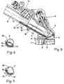
- the nozzle 16 is not pressurized is, then the elastomer part 15 is due to its Intrinsic elasticity on the support body 14 so that the Cross section of the inlet duct 6 in its essence round shape is not affected (Fig. 1 and Fig. 2).
- the expansion body With increasing pressure on the connector 16, the expansion body swells and forms in the inlet channel 6 near the inlet valve 7 a one-sided ramp 17 (Fig. 3), the cross section of the inlet channel 6 changed asymmetrically and thus deflects the gas flow in the inlet channel 6 so that behind the inlet valve 7 in the combustion chamber 5 in wanted Way makes a vortex.
- This vortex can be as roller running perpendicular to the cylinder axis, as parallel extending to the cylinder axis or as an intermediate form be trained.
- Figures 5 and 6 show a modified Embodiment of the invention.
- the support body 14 is connected with one in the cross section of the Inlet channel 6 extending stop 18 to which at the elastomer part 15 applies full articulation of the expansion body. This is an exactly reproducible height of the ramp 17 possible with full deflection of the expansion body.
- FIG. 7 Another modification of the invention shows Fig. 7, in which the support body 14 'on its support the wall 13 of the inlet duct 6 about the axis of the inlet duct 6 pivoted in the direction of arrow X controlled can be.
- the ramp 17 allows the gas flow to the inlet valve 7 not only change axially in one plane, but in several lying in the axis of the inlet channel 6 Layers change the flow direction.
- the target Vortex shape in the combustion chamber 5 can thus have a. wide range of engine operation can be affected.
Landscapes
- Engineering & Computer Science (AREA)
- Chemical & Material Sciences (AREA)
- Combustion & Propulsion (AREA)
- Mechanical Engineering (AREA)
- General Engineering & Computer Science (AREA)
- Combustion Methods Of Internal-Combustion Engines (AREA)
- Output Control And Ontrol Of Special Type Engine (AREA)
- Pistons, Piston Rings, And Cylinders (AREA)
Abstract
Description
- Fig. 1:
- einen Teilschnitt durch den Zylinderkopf einer Brennkraftmaschine entlang der Mittelachse eines Einlaßkanals bei geforderter hoher Zylinderfüllung;
- Fig. 2:
- einen Schnitt entlang der Linie A in Fig. 1;
- Fig. 3:
- den Teilschnitt nach Fig. 1 bei aufgeweitetem Dehnkörper;
- Fig. 4:
- einen Schnitt entlang der Linie B in Fig. 3;
- Fig. 5:
- einen Teilschnitt durch den Zylinderkopf einer Brennkraftmaschine entlang der Mittelachse eines Einlaßkanals mit einer Anschlagfläche für den Dehnkörper;
- Fig. 6:
- einen Schnitt entlang der Linie C in Fig. 5;
- Fig. 7:
- einen Schnitt analog dem Schnitt der Fig. 2 eines weiteren Ausführungsbeispiels.
Claims (5)
- Einlaßkanal für eine insbesondere fremdgezündete Hubkolben-Brennkraftmaschine mit Mitteln zum Verändern der Anströmungsrichtung des im Einlaßkanal geführten Gases auf ein am Ende des Einlaßkanals angeordnetes einen Verbrennungsraum abschließendes Einlaßventil, dadurch gekennzeichnet, daß die Mittel aus einem asymmetrisch an einer Wandung (13) des Einlaßkanals (6) angeordneten Dehnkörper gebildet sind, welcher durch gesteuertes Aufblähen seines Volumens eine Rampe (17) bildet und dadurch den Querschnitt des Einlaßkanals (6) asymmetrisch verändert.
- Einlaßkanal nach Anspruch 1, dadurch gekennzeichnet, daß der Dehnkörper von einem an der Wandung (13) des Einlaßkanals (6) anliegenden Tragkörper (14) und einem mit diesem an seinen Rändern gas- und flüssigkeitsdicht verbundenen Elastomerteil (15) gebildet ist, wobei zwischen Tragkörper (14) und Elastomerteil (15) ein Druckmedium durch einen Stutzen (16) gesteuert einbringbar ist.
- Einlaßkanal nach Anspruch 2, dadurch gekennzeichnet, daß der Tragkörper (14) einen Anschlag (18) bildet, welcher die maximale Ausdehnung des Dehnkörpers begrenzt.
- Einlaßkanal nach mindestens einem der Ansprüche 1 bis 3, dadurch gekennzeichnet, daß der Dehnkörper an der Wandung (13) des Einlaßkanals (6) um die Achse des Einlaßkanals (6) verschiebbar ist.
- Einlaßkanal nach mindestens einem der Ansprüche 1 bis 4, dadurch gekennzeichnet, daß das zum gesteuerten Aufblähen des Dehnkörpers verwendete Druckmedium als Flüssigkeit oder Gas von einer Pumpe geliefert ist, deren Druck in Abhängigkeit von den Motorparametern durch eine elektronische Steuerung bestimmt oder nach einem Kennfeld ausgewählt wird.
Applications Claiming Priority (2)
| Application Number | Priority Date | Filing Date | Title |
|---|---|---|---|
| DE19809052A DE19809052A1 (de) | 1998-03-04 | 1998-03-04 | Einlaßkanal für eine Brennkraftmaschine |
| DE19809052 | 1998-03-04 |
Publications (3)
| Publication Number | Publication Date |
|---|---|
| EP0940575A2 true EP0940575A2 (de) | 1999-09-08 |
| EP0940575A3 EP0940575A3 (de) | 2000-07-05 |
| EP0940575B1 EP0940575B1 (de) | 2006-10-04 |
Family
ID=7859568
Family Applications (1)
| Application Number | Title | Priority Date | Filing Date |
|---|---|---|---|
| EP99103776A Expired - Lifetime EP0940575B1 (de) | 1998-03-04 | 1999-02-26 | Einlasskanal für eine Brennkraftmaschine |
Country Status (2)
| Country | Link |
|---|---|
| EP (1) | EP0940575B1 (de) |
| DE (2) | DE19809052A1 (de) |
Cited By (2)
| Publication number | Priority date | Publication date | Assignee | Title |
|---|---|---|---|---|
| WO2004009989A1 (en) | 2002-07-18 | 2004-01-29 | Kohler Co. | Component for governing air flow in and around cylinder head port |
| WO2013034265A3 (de) * | 2011-09-07 | 2013-05-02 | Volkswagen Aktiengesellschaft | Strömungskörper, maskierungsmodul für den einlass einer brennkraftmaschine und brennkraftmaschine |
Families Citing this family (6)
| Publication number | Priority date | Publication date | Assignee | Title |
|---|---|---|---|---|
| DE10238396A1 (de) * | 2002-08-22 | 2004-02-26 | Adam Opel Ag | Variabler Einlasskanal für eine Hubkolben-Brennkraftmaschine |
| DE10313293A1 (de) * | 2003-03-25 | 2004-10-07 | Adam Opel Ag | Brennkraftmaschine mit variablem Einlasskanal |
| DE102006025267A1 (de) * | 2006-05-31 | 2007-12-06 | Rehau Ag + Co | Ansaugrohr zum Einsatz in einem Kraftfahrzeugverbrennungsmotor sowie Saugmodul für einen Verbrennungsmotor mit einem derartigen Ansaugrohr |
| DE102011002139A1 (de) * | 2011-04-18 | 2012-10-18 | Dr. Ing. H.C. F. Porsche Aktiengesellschaft | Sauganlage einer Brennkraftmaschine mit Tumbleschanze |
| US9784189B2 (en) * | 2015-01-28 | 2017-10-10 | Ford Global Technologies, Llc | Method and system for an engine variable charge motion system |
| DE102017202441A1 (de) * | 2017-02-15 | 2018-08-16 | Mahle International Gmbh | Ansaugarm eines Ansaugtrakts für eine direkt einspritzende Brennkraftmaschine, Frischluftverteiler und Brennkraftmaschine |
Citations (1)
| Publication number | Priority date | Publication date | Assignee | Title |
|---|---|---|---|---|
| DE9319545U1 (de) | 1993-12-20 | 1995-04-20 | FEV Motorentechnik GmbH & Co. KG, 52078 Aachen | Fremdgezündeter Kolbenmotor mit richtungsänderbarer Einströmung des Kraftstoff-Luft-Gemisches |
Family Cites Families (8)
| Publication number | Priority date | Publication date | Assignee | Title |
|---|---|---|---|---|
| DE1072005B (de) * | 1959-12-24 | Maschinenfabrik Augsburg Nürnberg A G Zweigniederlassung Nürnberg | Regelorgan aus Kunststoff fur den Einlaß kanal einer Brennkraftmaschine | |
| JPS531712A (en) * | 1976-06-29 | 1978-01-10 | Nissan Motor Co Ltd | Suction gas swirling device |
| DE2643326A1 (de) * | 1976-09-25 | 1978-03-30 | Daimler Benz Ag | Einlasskanal in einer viertakt- brennkraftmaschine |
| DE3518684A1 (de) * | 1985-05-24 | 1986-11-27 | Audi AG, 8070 Ingolstadt | Saugrohr fuer eine mehrzylindrige brennkraftmaschine |
| US4928638A (en) * | 1989-09-12 | 1990-05-29 | Overbeck Wayne W | Variable intake manifold |
| DE4445412C2 (de) * | 1994-12-20 | 1998-11-12 | Opel Adam Ag | Einlaßkanalsystem für eine fremdgezündete Brennkraftmaschine mit mindestens zwei in einem Zylinderkopf angeordneten Hub-Einlaßventilen pro Zylinder |
| WO1996026356A1 (fr) * | 1995-02-22 | 1996-08-29 | Alex Matesic | Dispositif de controle de flux gazeux pour moteurs a explosions |
| DE19531985A1 (de) * | 1995-08-30 | 1997-03-06 | Marco Herr | Ansaugsystem für eine Kolbenbrennkraftmaschine |
-
1998
- 1998-03-04 DE DE19809052A patent/DE19809052A1/de not_active Ceased
-
1999
- 1999-02-26 DE DE59913887T patent/DE59913887D1/de not_active Expired - Lifetime
- 1999-02-26 EP EP99103776A patent/EP0940575B1/de not_active Expired - Lifetime
Patent Citations (1)
| Publication number | Priority date | Publication date | Assignee | Title |
|---|---|---|---|---|
| DE9319545U1 (de) | 1993-12-20 | 1995-04-20 | FEV Motorentechnik GmbH & Co. KG, 52078 Aachen | Fremdgezündeter Kolbenmotor mit richtungsänderbarer Einströmung des Kraftstoff-Luft-Gemisches |
Cited By (5)
| Publication number | Priority date | Publication date | Assignee | Title |
|---|---|---|---|---|
| WO2004009989A1 (en) | 2002-07-18 | 2004-01-29 | Kohler Co. | Component for governing air flow in and around cylinder head port |
| EP1540166A4 (de) * | 2002-07-18 | 2008-06-18 | Kohler Co | Komponente zur luftstromregelung in einem und um einen zylinderkopfkanal |
| WO2013034265A3 (de) * | 2011-09-07 | 2013-05-02 | Volkswagen Aktiengesellschaft | Strömungskörper, maskierungsmodul für den einlass einer brennkraftmaschine und brennkraftmaschine |
| CN103782005A (zh) * | 2011-09-07 | 2014-05-07 | 大众汽车有限公司 | 用于燃烧发动机的进气道的引流体、掩蔽模块和燃烧发动机 |
| CN103782005B (zh) * | 2011-09-07 | 2016-11-09 | 大众汽车有限公司 | 用于燃烧发动机的进气道的引流体、掩蔽模块和燃烧发动机 |
Also Published As
| Publication number | Publication date |
|---|---|
| DE59913887D1 (de) | 2006-11-16 |
| DE19809052A1 (de) | 1999-09-09 |
| EP0940575A3 (de) | 2000-07-05 |
| EP0940575B1 (de) | 2006-10-04 |
Similar Documents
| Publication | Publication Date | Title |
|---|---|---|
| DE4039520B4 (de) | Kraftstoff-Einspritzventil | |
| DE68910775T2 (de) | Brennstoffeinspritzdüse mit veränderlicher Brennstoffsprühstrahlform. | |
| EP2480783B1 (de) | Kraftstoff-einspritzventil für eine brennkraftmaschine | |
| DE102008006994B4 (de) | Isolierkörperaufbau | |
| DE4228359A1 (de) | Einspritzdüse für Brennkraftmaschinen | |
| DE10334347A1 (de) | Kraftstoffeinspritzventil und Verbrennungsmotor mit Kraftstoffeinspritzventil | |
| DE102008049929A1 (de) | Niedrigdruckkraftstoffeinspritzer | |
| EP0940575A2 (de) | Einlasskanal für eine Brennkraftmaschine | |
| DE2727826C2 (de) | Gaseinblasvorrichtung für einen Verbrennungsmotor | |
| DE69802150T2 (de) | Funkengezündete Direkteinspritzbrennkraftmaschine | |
| EP0730090A2 (de) | Kraftstoffeinspritzventil für Brennkraftmaschinen | |
| EP0847484A1 (de) | Ansaugsystem für eine kolbenbrennkraftmaschine | |
| DE10341111A1 (de) | Ottomotor mit Direkteinspritzung und speziell gestalteten Mehrloch-Einspritzventilen | |
| EP1034366B1 (de) | Kolben für eine kolbenbrennkraftmaschine | |
| EP0731264A2 (de) | Einlasssytem für eine Zweitakt-Brennkraftmaschine | |
| DE2534730B2 (de) | Abgasrückführanordnung für eine Brennkraftmaschine | |
| DE60314226T2 (de) | Sprühmusterelement und Kraftstoffeinspritzventil mit demselben | |
| DE10122352A1 (de) | Brennstoffeinspritzsystem | |
| DE10140941A1 (de) | Ventilmechanismus mit einem variablen Ventilöffnungsquerschnitt | |
| EP1397590A1 (de) | Vorrichtung zur bestimmung zumindest eines parameters eines in einer leitung strömenden mediums mit einem filter zur aufnahme von schadstoffen in der leitung | |
| DE10208222A1 (de) | Brennstoffeinspritzventil | |
| DE102016221071B4 (de) | Injektor für eine mit einem gasförmigen Kraftstoff betriebene Brennkraftmaschine | |
| EP0149047A2 (de) | Zusatzluftvorrichtung für Brennkraftmaschinen | |
| AT503181B1 (de) | Einlasskanalanordnung für eine brennkraftmaschine | |
| DE19526524A1 (de) | Brennstoffdruckregelventil für Brennkraftmaschinen |
Legal Events
| Date | Code | Title | Description |
|---|---|---|---|
| PUAI | Public reference made under article 153(3) epc to a published international application that has entered the european phase |
Free format text: ORIGINAL CODE: 0009012 |
|
| AK | Designated contracting states |
Kind code of ref document: A2 Designated state(s): DE FR GB IT |
|
| AX | Request for extension of the european patent |
Free format text: AL;LT;LV;MK;RO;SI |
|
| PUAL | Search report despatched |
Free format text: ORIGINAL CODE: 0009013 |
|
| RIC1 | Information provided on ipc code assigned before grant |
Free format text: 7F 02M 31/00 A, 7F 02M 35/00 B, 7F 02F 1/42 B, 7F 02M 9/10 B, 7F 02D 9/18 B, 7F 02B 31/06 B |
|
| AK | Designated contracting states |
Kind code of ref document: A3 Designated state(s): AT BE CH CY DE DK ES FI FR GB GR IE IT LI LU MC NL PT SE |
|
| AX | Request for extension of the european patent |
Free format text: AL;LT;LV;MK;RO;SI |
|
| 17P | Request for examination filed |
Effective date: 20001222 |
|
| AKX | Designation fees paid |
Free format text: DE FR GB IT |
|
| 17Q | First examination report despatched |
Effective date: 20030221 |
|
| RIC1 | Information provided on ipc code assigned before grant |
Ipc: 7F 02B 31/06 B Ipc: 7F 02D 9/18 B Ipc: 7F 02M 9/10 B Ipc: 7F 02F 1/42 A |
|
| GRAP | Despatch of communication of intention to grant a patent |
Free format text: ORIGINAL CODE: EPIDOSNIGR1 |
|
| GRAS | Grant fee paid |
Free format text: ORIGINAL CODE: EPIDOSNIGR3 |
|
| GRAA | (expected) grant |
Free format text: ORIGINAL CODE: 0009210 |
|
| AK | Designated contracting states |
Kind code of ref document: B1 Designated state(s): DE FR GB IT |
|
| PG25 | Lapsed in a contracting state [announced via postgrant information from national office to epo] |
Ref country code: IT Free format text: LAPSE BECAUSE OF FAILURE TO SUBMIT A TRANSLATION OF THE DESCRIPTION OR TO PAY THE FEE WITHIN THE PRESCRIBED TIME-LIMIT;WARNING: LAPSES OF ITALIAN PATENTS WITH EFFECTIVE DATE BEFORE 2007 MAY HAVE OCCURRED AT ANY TIME BEFORE 2007. THE CORRECT EFFECTIVE DATE MAY BE DIFFERENT FROM THE ONE RECORDED. Effective date: 20061004 |
|
| REG | Reference to a national code |
Ref country code: GB Ref legal event code: FG4D Free format text: NOT ENGLISH |
|
| GBT | Gb: translation of ep patent filed (gb section 77(6)(a)/1977) |
Effective date: 20061019 |
|
| REF | Corresponds to: |
Ref document number: 59913887 Country of ref document: DE Date of ref document: 20061116 Kind code of ref document: P |
|
| ET | Fr: translation filed | ||
| PLBE | No opposition filed within time limit |
Free format text: ORIGINAL CODE: 0009261 |
|
| STAA | Information on the status of an ep patent application or granted ep patent |
Free format text: STATUS: NO OPPOSITION FILED WITHIN TIME LIMIT |
|
| 26N | No opposition filed |
Effective date: 20070705 |
|
| REG | Reference to a national code |
Ref country code: GB Ref legal event code: 732E Free format text: REGISTERED BETWEEN 20090219 AND 20090225 |
|
| REG | Reference to a national code |
Ref country code: GB Ref legal event code: 732E Free format text: REGISTERED BETWEEN 20090305 AND 20090311 |
|
| REG | Reference to a national code |
Ref country code: GB Ref legal event code: 732E Free format text: REGISTERED BETWEEN 20091029 AND 20091104 |
|
| REG | Reference to a national code |
Ref country code: GB Ref legal event code: 732E Free format text: REGISTERED BETWEEN 20091105 AND 20091111 |
|
| REG | Reference to a national code |
Ref country code: DE Ref legal event code: R081 Ref document number: 59913887 Country of ref document: DE Owner name: GM GLOBAL TECHNOLOGY OPERATIONS LLC (N. D. GES, US Free format text: FORMER OWNER: GM GLOBAL TECHNOLOGY OPERATIONS, INC., DETROIT, MICH., US Effective date: 20110323 Ref country code: DE Ref legal event code: R081 Ref document number: 59913887 Country of ref document: DE Owner name: GM GLOBAL TECHNOLOGY OPERATIONS LLC (N. D. GES, US Free format text: FORMER OWNER: GM GLOBAL TECHNOLOGY OPERATIONS, INC., DETROIT, US Effective date: 20110323 |
|
| PGFP | Annual fee paid to national office [announced via postgrant information from national office to epo] |
Ref country code: DE Payment date: 20110223 Year of fee payment: 13 Ref country code: FR Payment date: 20110218 Year of fee payment: 13 Ref country code: IT Payment date: 20110217 Year of fee payment: 13 |
|
| PGFP | Annual fee paid to national office [announced via postgrant information from national office to epo] |
Ref country code: GB Payment date: 20110223 Year of fee payment: 13 |
|
| GBPC | Gb: european patent ceased through non-payment of renewal fee |
Effective date: 20120226 |
|
| REG | Reference to a national code |
Ref country code: FR Ref legal event code: ST Effective date: 20121031 |
|
| PG25 | Lapsed in a contracting state [announced via postgrant information from national office to epo] |
Ref country code: IT Free format text: LAPSE BECAUSE OF NON-PAYMENT OF DUE FEES Effective date: 20120226 |
|
| REG | Reference to a national code |
Ref country code: DE Ref legal event code: R119 Ref document number: 59913887 Country of ref document: DE Effective date: 20120901 |
|
| PG25 | Lapsed in a contracting state [announced via postgrant information from national office to epo] |
Ref country code: GB Free format text: LAPSE BECAUSE OF NON-PAYMENT OF DUE FEES Effective date: 20120226 Ref country code: FR Free format text: LAPSE BECAUSE OF NON-PAYMENT OF DUE FEES Effective date: 20120229 |
|
| PG25 | Lapsed in a contracting state [announced via postgrant information from national office to epo] |
Ref country code: DE Free format text: LAPSE BECAUSE OF NON-PAYMENT OF DUE FEES Effective date: 20120901 |