EP0940575B1 - Einlasskanal für eine Brennkraftmaschine - Google Patents
Einlasskanal für eine BrennkraftmaschineInfo
- Publication number
- EP0940575B1 EP0940575B1 EP99103776A EP99103776A EP0940575B1 EP 0940575 B1 EP0940575 B1 EP 0940575B1 EP 99103776 A EP99103776 A EP 99103776A EP 99103776 A EP99103776 A EP 99103776A EP 0940575 B1 EP0940575 B1 EP 0940575B1
- Authority
- EP
- European Patent Office
- Prior art keywords
- inlet conduit
- expandable body
- combustion engine
- inlet
- wall
- Prior art date
- Legal status (The legal status is an assumption and is not a legal conclusion. Google has not performed a legal analysis and makes no representation as to the accuracy of the status listed.)
- Expired - Lifetime
Links
Images

Classifications
-
- F—MECHANICAL ENGINEERING; LIGHTING; HEATING; WEAPONS; BLASTING
- F02—COMBUSTION ENGINES; HOT-GAS OR COMBUSTION-PRODUCT ENGINE PLANTS
- F02F—CYLINDERS, PISTONS OR CASINGS, FOR COMBUSTION ENGINES; ARRANGEMENTS OF SEALINGS IN COMBUSTION ENGINES
- F02F1/00—Cylinders; Cylinder heads
- F02F1/24—Cylinder heads
- F02F1/42—Shape or arrangement of intake or exhaust channels in cylinder heads
- F02F1/4235—Shape or arrangement of intake or exhaust channels in cylinder heads of intake channels
- F02F1/4242—Shape or arrangement of intake or exhaust channels in cylinder heads of intake channels with a partition wall inside the channel
-
- F—MECHANICAL ENGINEERING; LIGHTING; HEATING; WEAPONS; BLASTING
- F02—COMBUSTION ENGINES; HOT-GAS OR COMBUSTION-PRODUCT ENGINE PLANTS
- F02B—INTERNAL-COMBUSTION PISTON ENGINES; COMBUSTION ENGINES IN GENERAL
- F02B31/00—Modifying induction systems for imparting a rotation to the charge in the cylinder
- F02B31/04—Modifying induction systems for imparting a rotation to the charge in the cylinder by means within the induction channel, e.g. deflectors
- F02B31/06—Movable means, e.g. butterfly valves
-
- F—MECHANICAL ENGINEERING; LIGHTING; HEATING; WEAPONS; BLASTING
- F02—COMBUSTION ENGINES; HOT-GAS OR COMBUSTION-PRODUCT ENGINE PLANTS
- F02F—CYLINDERS, PISTONS OR CASINGS, FOR COMBUSTION ENGINES; ARRANGEMENTS OF SEALINGS IN COMBUSTION ENGINES
- F02F1/00—Cylinders; Cylinder heads
- F02F1/24—Cylinder heads
- F02F1/42—Shape or arrangement of intake or exhaust channels in cylinder heads
- F02F1/4235—Shape or arrangement of intake or exhaust channels in cylinder heads of intake channels
- F02F1/425—Shape or arrangement of intake or exhaust channels in cylinder heads of intake channels with a separate deviation element inside the channel
-
- F—MECHANICAL ENGINEERING; LIGHTING; HEATING; WEAPONS; BLASTING
- F02—COMBUSTION ENGINES; HOT-GAS OR COMBUSTION-PRODUCT ENGINE PLANTS
- F02M—SUPPLYING COMBUSTION ENGINES IN GENERAL WITH COMBUSTIBLE MIXTURES OR CONSTITUENTS THEREOF
- F02M19/00—Details, component parts, or accessories of carburettors, not provided for in, or of interest apart from, the apparatus of groups F02M1/00 - F02M17/00
- F02M19/08—Venturis
- F02M19/085—Venturis venturi section being made from elastic material, e.g. from rubber-like material
-
- Y—GENERAL TAGGING OF NEW TECHNOLOGICAL DEVELOPMENTS; GENERAL TAGGING OF CROSS-SECTIONAL TECHNOLOGIES SPANNING OVER SEVERAL SECTIONS OF THE IPC; TECHNICAL SUBJECTS COVERED BY FORMER USPC CROSS-REFERENCE ART COLLECTIONS [XRACs] AND DIGESTS
- Y02—TECHNOLOGIES OR APPLICATIONS FOR MITIGATION OR ADAPTATION AGAINST CLIMATE CHANGE
- Y02T—CLIMATE CHANGE MITIGATION TECHNOLOGIES RELATED TO TRANSPORTATION
- Y02T10/00—Road transport of goods or passengers
- Y02T10/10—Internal combustion engine [ICE] based vehicles
- Y02T10/12—Improving ICE efficiencies
Definitions
- the invention relates to an inlet channel for a particular spark-ignited reciprocating internal combustion engine having means for varying the direction of flow of the guided gas in the inlet channel to an inlet valve arranged at the inlet valve to a combustion chamber.
- Such an inlet channel is described with DE 93 19 545 U1.
- the channel cross-section is divided by a wall into two sub-channels, which merge into an inlet region immediately before an inlet valve closing the combustion chamber of the internal combustion engine, wherein the wall forms a dividing plane which extends at least at the inlet region transverse to the axis of the cylinder of the internal combustion engine and wherein one of the sub-channels is provided with a controllable throttle.
- Such an inlet channel has the disadvantage that the throttle valve, which is additionally arranged in its partial cross section, obstructs the unimpeded passage of the gas, in particular at higher rotational speeds of the internal combustion engine, even in the opened state. This leads to unwanted eddies in the flow and to loss of fill. Likewise, flow separations at the downstream edge of the wall separating the two subchannels are unavoidable, so that filling level losses are also caused thereby.
- US 4 928 638 aims to maximize the vaporization of the fuel-air mixture and to increase the flow velocity thereof in response to a variety of engine parameters.
- an inflatable bladder is introduced into the intake channel for the controlled constriction.
- a suction pipe in which a flap which can be opened on one side is provided, which can be placed at different angles in the suction pipe, so that in this way the flow cross section through the suction pipe is changed.
- DE 26 43 326 A1 discloses an inlet channel according to the preamble of claim 1.
- the expansion element is here formed by a tube which completely lines the wall of the inlet channel. A clearance between the hose and the wall communicates with a portion of the intake passage immediately in front of the valve seat.
- the degree of expansion of the expansion body according to one embodiment, by the ratio of the pressures in the interior of the hose on the one hand and on the valve seat on the other hand automatically; Alternatively, it can also be controlled mechanically, hydraulically or inductively.
- the invention has for its object to improve an inlet channel of the generic type so that the cross-section of the inlet channel can be set exactly reproducible at full deflection of the expansion body in a simple manner.
- FIG. 1 shows a partial section through the cylinder head of an internal combustion engine not according to the invention along the central axis of an intake duct with a required high cylinder charge
- Fig. 2 is a section along the line A in Fig. 1;
- Fig. 3 the partial section of Figure 1 with expanded expansion body.
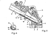
- FIG. 5 shows a partial section through the cylinder head of an internal combustion engine along the central axis of an inlet duct according to the invention with a stop face for the expansion body;
- a cylinder block 1 of an internal combustion engine with cylinders 2 and piston 3 is upwardly through a cylinder head 4 completed. Between the piston 3 and the cylinder head 4, a combustion chamber 5 is formed.
- an inlet channel 6 which leads from an air filter, not shown, to an inlet valve 7.
- the intake valve 7 is to be opened by a cam follower 8 against the force of a valve closing spring 9 by a camshaft 10.
- a fuel injection valve 11 connects.
- a spark plug 12 extends with its electrodes in the combustion chamber 5.
- On a wall 13 of the inlet channel 6 is a flat support body 14.
- the support body 14 is provided with an opening and an adjoining nozzle 16 which projects through an opening in the wall 13 of the inlet channel 6.
- a controllable pressure source for. B. a gas or liquid pump connected.
- the pressure of this pressure source is preferably controllable on the basis of a characteristic field by the engine control as a function of the engine parameters.
- the support body 14 and the elastomer part 15 together form an expansion body, which expands under pressure in its interior into the inlet channel 6 inside.
- connection piece 16 If the connection piece 16 is not subjected to pressure, then the elastomer part 15 lies flat against its own elasticity on the support body 14, so that the cross-section of the inlet channel 6 is not impaired in its essentially round shape (FIGS. 1 and 2).
- the expansion body With increasing pressure at the neck 16, the expansion body inflates and forms in the inlet channel 6 near the inlet valve 7 a unilateral ramp 17 (FIG. 3), which asymmetrically alters the cross-section of the inlet channel 6 and thus deflects the gas flow in the inlet channel 6 in such a way behind the inlet valve 7 in the combustion chamber 5 in a desired manner forms a vortex.
- This vortex can be designed as a roll running perpendicular to the cylinder axis, as extending parallel to the cylinder axis or as an intermediate shape.
- FIGS. 5 and 6 show a modification according to the invention of the above-described internal combustion engine.
- the support body 14 is in this case connected to a stop 18 extending in the cross-section of the inlet channel 6, against which the elastomer part 15 strikes when the expansion element is fully deflected.
- a precisely reproducible height of the ramp 17 at full deflection of the expansion body is possible.
Landscapes
- Engineering & Computer Science (AREA)
- Chemical & Material Sciences (AREA)
- Combustion & Propulsion (AREA)
- Mechanical Engineering (AREA)
- General Engineering & Computer Science (AREA)
- Combustion Methods Of Internal-Combustion Engines (AREA)
- Pistons, Piston Rings, And Cylinders (AREA)
- Output Control And Ontrol Of Special Type Engine (AREA)
Description
- Die Erfindung betrifft einen Einlasskanal für eine insbesondere fremdgezündete Hubkolben-Brennkraftmaschine mit Mitteln zum Verändern der Anströmungsrichtung des im Einlasskanal geführten Gases auf ein am Ende des Einlasskanals angeordnetes Einlassventil zu einem Verbrennungsraum.
- Der Zweck eines solches Einlasskanals besteht darin, bei bestimmten Betriebsbereichen der Brennkraftmaschine in gezielter Weise eine drallartige Bewegung der Zylinderladung im Verbrennungsraum zu erzielen und so eine stabile Verbrennung zu sichern, wohingegen bei anderen Betriebszuständen der Brennkraftmaschine eine solche Drallbewegung unerwünscht ist und vermieden werden soll.
- Ein derartiger Einlasskanal ist mit DE 93 19 545 U1 beschrieben. Bei diesem Einlasskanal ist der Kanalquerschnitt durch eine Wand in zwei Teilkanäle unterteilt, die sich unmittelbar vor einem den Brennraum der Brennkraftmaschine verschließenden Einlassventil zu einem Einlassbereich vereinigen, wobei die Wand eine Teilungsebene bildet, die zumindest am Einlassbereich quer zur Achse des Zylinders der Brennkraftmaschine verläuft und wobei einer der Teilkanäle mit einer steuerbaren Drosselklappe versehen ist.
- Ein solcher Einlasskanal hat den Nachteil, dass die in seinem Teilquerschnitt zusätzlich angeordnete Drosselklappe auch im geöffneten Zustand den ungehinderten Durchtritt des Gases insbesondere bei höheren Drehzahlen der Brennkraftmaschine behindert. Dies führt zu ungewollten Wirbelbildungen im Strömungsverlauf und zu Füllungsgradverlusten. Ebenso sind Strömungsablösungen an der stromabliegenden Kante der die beiden Teilkanäle trennenden Wand unvermeidlich, so dass auch dadurch Füllungsgradverluste verursacht werden.
- DE 41 35 271 A1 beschreibt ein Saugrohr einer Brennkraftmaschine, bei dem zur Anpassung des Schwingungsverhaltens an den motorischen Betrieb der Brennkraftmaschine der Durchflussquerschnitt mittels eines elastisch aufblähbaren Dehnkörpers verändert wird, wobei dieser Dehnkörper ringförmig ausgebildet ist und den Durchflussquerschnitt konzentrisch verändert. Eine Beeinflussung der Einströmungsrichtung des Gases in den Zylinder der Brennkraftmaschine ist nach der hier aufgezeigten technischen Lehre nicht möglich.
- Die US 4 928 638 verfolgt das Ziel, die Verdampfung des Kraftstoff-Luft-Gemisches zu maximieren und die Strömungsgeschwindigkeit desselben in Abhängigkeit einer Vielzahl von Motorparametern zu erhöhen. Hierzu wird in den Ansaugkanal zur gesteuerten Einengung eine aufblasbare Blase eingebracht.
- Aus der JP 53 001712 A ist ein Saugrohr bekannt, in dem eine einseitig aufklappbare Klappe vorgesehen ist, welche unter verschiedenen Winkeln in das Saugrohr gestellt werden kann, so dass auf diese Weise der Durchflussquerschnitt durch das Saugrohr verändert wird.
- DE 26 43 326 A1 offenbart einen Einlasskanal nach dem Oberbegriff des Anspruchs 1. Der Dehnkörper ist hier durch einen Schlauch gebildet, der die Wandung des Einlasskanals vollumfänglich auskleidet. Ein Zwischenraum zwischen dem Schlauch und der Wandung kommuniziert mit einem Abschnitt des Einlasskanals unmittelbar vor dem Ventilsitz. Der Dehnungsgrad des Dehnkörpers stellt sich einem Ausführungsbeispiel zufolge durch das Verhältnis der Drücke im Innern des Schlauchs einerseits und am Ventilsitz andererseits selbsttätig ein; alternativ kann er auch mechanisch, hydraulisch oder induktiv steuerbar sein.
- Der Erfindung liegt die Aufgabe zugrunde, einen Einlasskanal der gattungsgemäßen Art so zu verbessern, dass der Querschnitt des Einlasskanals bei voller Auslenkung des Dehnkörpers auf einfache Weise exakt reproduzierbar eingestellt werden kann.
- Die Erfindung löst diese Aufgabe mit den Merkmalen des Anspruches 1. Vorteilhafte Weiterbildungen der Erfindung sind Gegenstand der Unteransprüche.
- Ausführungsbeispiele der Erfindung sind nachstehend anhand von Zeichnungen näher beschrieben. Es zeigen
- Fig. 1: einen Teilschnitt durch den Zylinderkopf einer nicht erfindungsgemäßen Brennkraftmaschine entlang der Mittelachse eines Einlasskanals bei geforderter hoher Zylinderfüllung;
- Fig. 2: einen Schnitt entlang der Linie A in Fig. 1;
- Fig. 3: den Teilschnitt nach Fig. 1 bei aufgeweitetem Dehnkörper;
- Fig. 4: einen Schnitt entlang der Linie B in Fig. 3;
- Fig. 5: einen Teilschnitt durch den Zylinderkopf einer Brennkraftmaschine entlang der Mittelachse eines erfindungsgemäßen Einlasskanals mit einer Anschlagfläche für den Dehnkörper; und
- Fig. 6: einen Schnitt entlang der Linie C in Fig. 5.
- Ein Zylinderblock 1 einer Brennkraftmaschine mit Zylindern 2 und Kolben 3 ist nach oben durch einen Zylinderkopf 4 abgeschlossen. Zwischen dem Kolben 3 und dem Zylinderkopf 4 ist ein Brennraum 5 gebildet. Im Zylinderkopf 4 befindet sich für jeden der Zylinder 2 ein Einlasskanal 6, der von einem nicht dargestellten Luftfilter zu einem Einlassventil 7 führt. Das Einlassventil 7 ist über einen Schlepphebel 8 entgegen der Kraft einer Ventilschließfeder 9 durch eine Nockenwelle 10 zu öffnen. An den Einlasskanal 6 schließt sich ein Kraftstoff-Einspritzventil 11 an. Eine Zündkerze 12 erstreckt sich mit ihren Elektroden in den Brennraum 5. An einer Wandung 13 des Einlasskanals 6 befindet sich ein flächiger Tragkörper 14. Dieser trägt ein Elastomerteil 15, das mit seinen Rändern gas- und flüssigkeitsdicht am Tragkörper 14 befestigt ist. Der Tragkörper 14 ist mit einer Öffnung und einem sich daran anschließenden Stutzen 16 versehen, der durch eine Öffnung der Wandung 13 des Einlasskanals 6 ragt. An diesem Stutzen 16 ist eine nicht dargestellte Leitung zu einer regelbaren Druckquelle, z. B. einer Gas- oder Flüssigkeitspumpe, angeschlossen. Der Druck dieser Druck- quelle ist vorzugsweise anhand eines Kennfeldes durch die Motorsteuerung in Abhängigkeit von den Motorparametern steuerbar. Der Tragkörper 14 und das Elastomerteil 15 bilden zusammen einen Dehnkörper, der sich unter Druck in seinem Inneren in den Einlasskanal 6 hinein ausdehnt.
- Wenn der Stutzen 16 nicht von Druck beaufschlagt ist, dann liegt das Elastomerteil 15 durch seine Eigenelastizität am Tragkörper 14 flächig an, so dass der Querschnitt des Einlasskanals 6 in seiner im Wesentlichen runden Form nicht beeinträchtigt ist (Fig. 1 und Fig. 2). Mit zunehmendem Druck am Stutzen 16 bläht sich der Dehnkörper auf und bildet im Einlasskanal 6 nahe dem Einlassventil 7 eine einseitige Rampe 17 (Fig. 3), die den Querschnitt des Einlasskanals 6 asymmetrisch verändert und damit den Gasstrom im Einlasskanal 6 so ablenkt, dass sich hinter dem Einlassventil 7 im Verbrennungsraum 5 in gewollter Weise ein Wirbel bildet. Dieser Wirbel kann als senkrecht zur Zylinderachse verlaufende Walze, als parallel zur Zylinderachse verlaufend oder als Zwischenform ausgebildet sein.
- Die Figuren 5 und 6 zeigen eine erfindungsgemäße Abwandlung der oben beschriebenen Brennkraftmaschine. Der Tragkörper 14 ist dabei verbunden mit einem sich in den Querschnitt des Einlasskanals 6 erstreckenden Anschlag 18, an den sich bei voller Auslenkung des Dehnkörpers das Elastomerteil 15 anlegt. Somit ist eine exakt reproduzierbare Höhe der Rampe 17 bei voller Auslenkung des Dehnkörpers möglich.
Claims (3)
- Einlasskanal für eine insbesondere fremdgezündete Hubkolben-Brennkraftmaschine mit Mitteln zum Verändern der Anströmungsrichtung des im Einlasskanal geführten Gases auf ein am Ende des Einlasskanals angeordnetes einen Verbrennungsraum abschließendes Einlassventil, wobei die Mittel aus einem asymmetrisch an einer Wandung (13) des Einlasskanals (6) angeordneten Dehnkörper gebildet sind, welcher durch gesteuertes Aufblähen seines Volumens eine Rampe (17) bildet und dadurch den Querschnitt des Einlasskanals (6) bis zu dessen Ende asymmetrisch verändert, und wobei der Dehnkörper ein Elastomerteil (15) umfasst, dadurch gekennzeichnet, dass der Dehnkörper ferner einen an der Wandung (13) des Einlasskanals (6) anliegenden Tragkörper (14) umfasst, der mit den Rändern des Elastomerteils (15) gas- und flüssigkeitsdicht verbunden ist, wobei zwischen Tragkörper (14) und Elastomerteil (15) ein Druckmedium durch einen Stutzen (16) gesteuert einbringbar ist, und dass der Tragkörper (14) einen Anschlag (18) bildet, welcher die maximale Ausdehnung des Dehnkörpers begrenzt.
- Einlasskanal nach Anspruch 1, dadurch gekennzeichnet, dass der Dehnkörper an der Wandung (13) des Einlasskanals (6) um die Achse des Einlasskanals (6) verschiebbar ist.
- Einlasskanal nach Anspruch 1 oder 2, dadurch gekennzeichnet, dass das zum gesteuerten Aufblähen des Dehnkörpers verwendete Druckmedium als Flüssigkeit oder Gas von einer Pumpe geliefert ist, deren Druck in Abhängigkeit von den Motorparametern durch eine elektronische Steuerung bestimmt oder nach einem Kennfeld ausgewählt wird.
Applications Claiming Priority (2)
| Application Number | Priority Date | Filing Date | Title |
|---|---|---|---|
| DE19809052A DE19809052A1 (de) | 1998-03-04 | 1998-03-04 | Einlaßkanal für eine Brennkraftmaschine |
| DE19809052 | 1998-03-04 |
Publications (3)
| Publication Number | Publication Date |
|---|---|
| EP0940575A2 EP0940575A2 (de) | 1999-09-08 |
| EP0940575A3 EP0940575A3 (de) | 2000-07-05 |
| EP0940575B1 true EP0940575B1 (de) | 2006-10-04 |
Family
ID=7859568
Family Applications (1)
| Application Number | Title | Priority Date | Filing Date |
|---|---|---|---|
| EP99103776A Expired - Lifetime EP0940575B1 (de) | 1998-03-04 | 1999-02-26 | Einlasskanal für eine Brennkraftmaschine |
Country Status (2)
| Country | Link |
|---|---|
| EP (1) | EP0940575B1 (de) |
| DE (2) | DE19809052A1 (de) |
Families Citing this family (8)
| Publication number | Priority date | Publication date | Assignee | Title |
|---|---|---|---|---|
| US6742488B2 (en) * | 2002-07-18 | 2004-06-01 | Kohler Co. | Component for governing air flow in and around cylinder head port |
| DE10238396A1 (de) * | 2002-08-22 | 2004-02-26 | Adam Opel Ag | Variabler Einlasskanal für eine Hubkolben-Brennkraftmaschine |
| DE10313293A1 (de) * | 2003-03-25 | 2004-10-07 | Adam Opel Ag | Brennkraftmaschine mit variablem Einlasskanal |
| DE102006025267A1 (de) * | 2006-05-31 | 2007-12-06 | Rehau Ag + Co | Ansaugrohr zum Einsatz in einem Kraftfahrzeugverbrennungsmotor sowie Saugmodul für einen Verbrennungsmotor mit einem derartigen Ansaugrohr |
| DE102011002139A1 (de) * | 2011-04-18 | 2012-10-18 | Dr. Ing. H.C. F. Porsche Aktiengesellschaft | Sauganlage einer Brennkraftmaschine mit Tumbleschanze |
| DE102011112862A1 (de) * | 2011-09-07 | 2013-03-07 | Volkswagen Aktiengesellschaft | Brennkraftmaschine, Maskierungsmodul und Strömungskörper |
| US9784189B2 (en) * | 2015-01-28 | 2017-10-10 | Ford Global Technologies, Llc | Method and system for an engine variable charge motion system |
| DE102017202441A1 (de) * | 2017-02-15 | 2018-08-16 | Mahle International Gmbh | Ansaugarm eines Ansaugtrakts für eine direkt einspritzende Brennkraftmaschine, Frischluftverteiler und Brennkraftmaschine |
Family Cites Families (9)
| Publication number | Priority date | Publication date | Assignee | Title |
|---|---|---|---|---|
| DE1072005B (de) * | 1959-12-24 | Maschinenfabrik Augsburg Nürnberg A G Zweigniederlassung Nürnberg | Regelorgan aus Kunststoff fur den Einlaß kanal einer Brennkraftmaschine | |
| JPS531712A (en) * | 1976-06-29 | 1978-01-10 | Nissan Motor Co Ltd | Suction gas swirling device |
| DE2643326A1 (de) * | 1976-09-25 | 1978-03-30 | Daimler Benz Ag | Einlasskanal in einer viertakt- brennkraftmaschine |
| DE3518684A1 (de) * | 1985-05-24 | 1986-11-27 | Audi AG, 8070 Ingolstadt | Saugrohr fuer eine mehrzylindrige brennkraftmaschine |
| US4928638A (en) * | 1989-09-12 | 1990-05-29 | Overbeck Wayne W | Variable intake manifold |
| DE9319545U1 (de) | 1993-12-20 | 1995-04-20 | FEV Motorentechnik GmbH & Co. KG, 52078 Aachen | Fremdgezündeter Kolbenmotor mit richtungsänderbarer Einströmung des Kraftstoff-Luft-Gemisches |
| DE4445412C2 (de) * | 1994-12-20 | 1998-11-12 | Opel Adam Ag | Einlaßkanalsystem für eine fremdgezündete Brennkraftmaschine mit mindestens zwei in einem Zylinderkopf angeordneten Hub-Einlaßventilen pro Zylinder |
| WO1996026356A1 (fr) * | 1995-02-22 | 1996-08-29 | Alex Matesic | Dispositif de controle de flux gazeux pour moteurs a explosions |
| DE19531985A1 (de) * | 1995-08-30 | 1997-03-06 | Marco Herr | Ansaugsystem für eine Kolbenbrennkraftmaschine |
-
1998
- 1998-03-04 DE DE19809052A patent/DE19809052A1/de not_active Ceased
-
1999
- 1999-02-26 DE DE59913887T patent/DE59913887D1/de not_active Expired - Lifetime
- 1999-02-26 EP EP99103776A patent/EP0940575B1/de not_active Expired - Lifetime
Also Published As
| Publication number | Publication date |
|---|---|
| DE59913887D1 (de) | 2006-11-16 |
| DE19809052A1 (de) | 1999-09-09 |
| EP0940575A3 (de) | 2000-07-05 |
| EP0940575A2 (de) | 1999-09-08 |
Similar Documents
| Publication | Publication Date | Title |
|---|---|---|
| DE4039520B4 (de) | Kraftstoff-Einspritzventil | |
| DE4135271C2 (de) | Saugrohr | |
| DE4228359A1 (de) | Einspritzdüse für Brennkraftmaschinen | |
| DE102008006994B4 (de) | Isolierkörperaufbau | |
| DE10334347B4 (de) | Kraftstoffeinspritzventil und Verbrennungsmotor mit Kraftstoffeinspritzventil | |
| DE102017219932A1 (de) | Injektor zur Eindüsung von gasförmigem Kraftstoff | |
| EP1034371B1 (de) | Kraftstoffeinspritzventil für eine brennkraftmaschine | |
| DE102008049929A1 (de) | Niedrigdruckkraftstoffeinspritzer | |
| DE102005019580B4 (de) | Kraftstoffeinspritzdüse | |
| DE602004002969T2 (de) | Dämpfer für Common Rail Kraftstoffverteiler | |
| EP0730090A2 (de) | Kraftstoffeinspritzventil für Brennkraftmaschinen | |
| EP0940575A2 (de) | Einlasskanal für eine Brennkraftmaschine | |
| DE69226286T2 (de) | Kombinierte kraftstoffdruckregel- und einspritzvorrichtung | |
| DE10341111A1 (de) | Ottomotor mit Direkteinspritzung und speziell gestalteten Mehrloch-Einspritzventilen | |
| EP0847484A1 (de) | Ansaugsystem für eine kolbenbrennkraftmaschine | |
| DE3836550C2 (de) | ||
| DE2534730C3 (de) | Abgasrückführanordnung für eine Brennkraftmaschine | |
| DE102013209272A1 (de) | Ventil zum Zumessen von Fluid | |
| DE10032740A1 (de) | Luftansaugvorrichtung für eine Brennkraftmaschine | |
| WO2024160398A1 (de) | Strömungsoptimierter gasinjektor | |
| EP0730089A1 (de) | Kraftstoffeinspritzventil für Brennkraftmaschinen | |
| DE60314226T2 (de) | Sprühmusterelement und Kraftstoffeinspritzventil mit demselben | |
| DE69932678T2 (de) | Direkteingespritzte Brennkraftmaschine | |
| DE102016123826A1 (de) | Gemischbildungsvorrichtung für einen Gasmotor und Gasmotor | |
| DE102016116071A1 (de) | In den Einlasskrümmer integrierter Unterdrucksolenoid zum Steuern eines CMCV-Unterdrucksystems |
Legal Events
| Date | Code | Title | Description |
|---|---|---|---|
| PUAI | Public reference made under article 153(3) epc to a published international application that has entered the european phase |
Free format text: ORIGINAL CODE: 0009012 |
|
| AK | Designated contracting states |
Kind code of ref document: A2 Designated state(s): DE FR GB IT |
|
| AX | Request for extension of the european patent |
Free format text: AL;LT;LV;MK;RO;SI |
|
| PUAL | Search report despatched |
Free format text: ORIGINAL CODE: 0009013 |
|
| RIC1 | Information provided on ipc code assigned before grant |
Free format text: 7F 02M 31/00 A, 7F 02M 35/00 B, 7F 02F 1/42 B, 7F 02M 9/10 B, 7F 02D 9/18 B, 7F 02B 31/06 B |
|
| AK | Designated contracting states |
Kind code of ref document: A3 Designated state(s): AT BE CH CY DE DK ES FI FR GB GR IE IT LI LU MC NL PT SE |
|
| AX | Request for extension of the european patent |
Free format text: AL;LT;LV;MK;RO;SI |
|
| 17P | Request for examination filed |
Effective date: 20001222 |
|
| AKX | Designation fees paid |
Free format text: DE FR GB IT |
|
| 17Q | First examination report despatched |
Effective date: 20030221 |
|
| RIC1 | Information provided on ipc code assigned before grant |
Ipc: 7F 02B 31/06 B Ipc: 7F 02D 9/18 B Ipc: 7F 02M 9/10 B Ipc: 7F 02F 1/42 A |
|
| GRAP | Despatch of communication of intention to grant a patent |
Free format text: ORIGINAL CODE: EPIDOSNIGR1 |
|
| GRAS | Grant fee paid |
Free format text: ORIGINAL CODE: EPIDOSNIGR3 |
|
| GRAA | (expected) grant |
Free format text: ORIGINAL CODE: 0009210 |
|
| AK | Designated contracting states |
Kind code of ref document: B1 Designated state(s): DE FR GB IT |
|
| PG25 | Lapsed in a contracting state [announced via postgrant information from national office to epo] |
Ref country code: IT Free format text: LAPSE BECAUSE OF FAILURE TO SUBMIT A TRANSLATION OF THE DESCRIPTION OR TO PAY THE FEE WITHIN THE PRESCRIBED TIME-LIMIT;WARNING: LAPSES OF ITALIAN PATENTS WITH EFFECTIVE DATE BEFORE 2007 MAY HAVE OCCURRED AT ANY TIME BEFORE 2007. THE CORRECT EFFECTIVE DATE MAY BE DIFFERENT FROM THE ONE RECORDED. Effective date: 20061004 |
|
| REG | Reference to a national code |
Ref country code: GB Ref legal event code: FG4D Free format text: NOT ENGLISH |
|
| GBT | Gb: translation of ep patent filed (gb section 77(6)(a)/1977) |
Effective date: 20061019 |
|
| REF | Corresponds to: |
Ref document number: 59913887 Country of ref document: DE Date of ref document: 20061116 Kind code of ref document: P |
|
| ET | Fr: translation filed | ||
| PLBE | No opposition filed within time limit |
Free format text: ORIGINAL CODE: 0009261 |
|
| STAA | Information on the status of an ep patent application or granted ep patent |
Free format text: STATUS: NO OPPOSITION FILED WITHIN TIME LIMIT |
|
| 26N | No opposition filed |
Effective date: 20070705 |
|
| REG | Reference to a national code |
Ref country code: GB Ref legal event code: 732E Free format text: REGISTERED BETWEEN 20090219 AND 20090225 |
|
| REG | Reference to a national code |
Ref country code: GB Ref legal event code: 732E Free format text: REGISTERED BETWEEN 20090305 AND 20090311 |
|
| REG | Reference to a national code |
Ref country code: GB Ref legal event code: 732E Free format text: REGISTERED BETWEEN 20091029 AND 20091104 |
|
| REG | Reference to a national code |
Ref country code: GB Ref legal event code: 732E Free format text: REGISTERED BETWEEN 20091105 AND 20091111 |
|
| REG | Reference to a national code |
Ref country code: DE Ref legal event code: R081 Ref document number: 59913887 Country of ref document: DE Owner name: GM GLOBAL TECHNOLOGY OPERATIONS LLC (N. D. GES, US Free format text: FORMER OWNER: GM GLOBAL TECHNOLOGY OPERATIONS, INC., DETROIT, MICH., US Effective date: 20110323 Ref country code: DE Ref legal event code: R081 Ref document number: 59913887 Country of ref document: DE Owner name: GM GLOBAL TECHNOLOGY OPERATIONS LLC (N. D. GES, US Free format text: FORMER OWNER: GM GLOBAL TECHNOLOGY OPERATIONS, INC., DETROIT, US Effective date: 20110323 |
|
| PGFP | Annual fee paid to national office [announced via postgrant information from national office to epo] |
Ref country code: DE Payment date: 20110223 Year of fee payment: 13 Ref country code: FR Payment date: 20110218 Year of fee payment: 13 Ref country code: IT Payment date: 20110217 Year of fee payment: 13 |
|
| PGFP | Annual fee paid to national office [announced via postgrant information from national office to epo] |
Ref country code: GB Payment date: 20110223 Year of fee payment: 13 |
|
| GBPC | Gb: european patent ceased through non-payment of renewal fee |
Effective date: 20120226 |
|
| REG | Reference to a national code |
Ref country code: FR Ref legal event code: ST Effective date: 20121031 |
|
| PG25 | Lapsed in a contracting state [announced via postgrant information from national office to epo] |
Ref country code: IT Free format text: LAPSE BECAUSE OF NON-PAYMENT OF DUE FEES Effective date: 20120226 |
|
| REG | Reference to a national code |
Ref country code: DE Ref legal event code: R119 Ref document number: 59913887 Country of ref document: DE Effective date: 20120901 |
|
| PG25 | Lapsed in a contracting state [announced via postgrant information from national office to epo] |
Ref country code: GB Free format text: LAPSE BECAUSE OF NON-PAYMENT OF DUE FEES Effective date: 20120226 Ref country code: FR Free format text: LAPSE BECAUSE OF NON-PAYMENT OF DUE FEES Effective date: 20120229 |
|
| PG25 | Lapsed in a contracting state [announced via postgrant information from national office to epo] |
Ref country code: DE Free format text: LAPSE BECAUSE OF NON-PAYMENT OF DUE FEES Effective date: 20120901 |