EP0940601B1 - Dispositif de commande avec un élément de commande sur lequel agit une force de réaction proportionnelle au déplacement - Google Patents
Dispositif de commande avec un élément de commande sur lequel agit une force de réaction proportionnelle au déplacement Download PDFInfo
- Publication number
- EP0940601B1 EP0940601B1 EP99103665A EP99103665A EP0940601B1 EP 0940601 B1 EP0940601 B1 EP 0940601B1 EP 99103665 A EP99103665 A EP 99103665A EP 99103665 A EP99103665 A EP 99103665A EP 0940601 B1 EP0940601 B1 EP 0940601B1
- Authority
- EP
- European Patent Office
- Prior art keywords
- spring
- controlling
- negative stiffness
- controlling device
- stiffness
- Prior art date
- Legal status (The legal status is an assumption and is not a legal conclusion. Google has not performed a legal analysis and makes no representation as to the accuracy of the status listed.)
- Expired - Lifetime
Links
Images


Classifications
-
- F—MECHANICAL ENGINEERING; LIGHTING; HEATING; WEAPONS; BLASTING
- F16—ENGINEERING ELEMENTS AND UNITS; GENERAL MEASURES FOR PRODUCING AND MAINTAINING EFFECTIVE FUNCTIONING OF MACHINES OR INSTALLATIONS; THERMAL INSULATION IN GENERAL
- F16F—SPRINGS; SHOCK-ABSORBERS; MEANS FOR DAMPING VIBRATION
- F16F3/00—Spring units consisting of several springs, e.g. for obtaining a desired spring characteristic
- F16F3/02—Spring units consisting of several springs, e.g. for obtaining a desired spring characteristic with springs made of steel or of other material having low internal friction
- F16F3/026—Spring units consisting of several springs, e.g. for obtaining a desired spring characteristic with springs made of steel or of other material having low internal friction to give a zero-spring rate characteristic
Definitions
- the invention relates to an adjusting device having the features of the preamble of claim 1.
- path-dependent restoring forces When using adjusting devices with any adjusting elements, which are also referred to as translators, occur path-dependent restoring forces, which reduce the efficiency of the adjusting element of the adjusting device against theoretically achievable values.
- the path-dependent restoring forces are typically based on the positive stiffness of a structure to be adjusted, which acts on the actuator, but also, for example, on the stiffness of elastic means with which a compressive bias is applied to an actuator with a piezoelectric crystal to safely avoid tensile stresses of the piezoelectric crystal ,
- the progressiveness of the restoring forces with the travel of the actuator reduces the effective change in length l of the adjusting device with respect to the achievable without elastic force change in length of the adjusting device l o .
- c R is the rigidity of the restoring force
- ie the structure including the rigidity of an elastic element biasing the actuator
- c S is the inherent rigidity of the actuator.
- EP 0 127 741 A1 is a spring with negative stiffness in a zero crossing of their travel for the technical Field of suspension of motor vehicles known. It can the Zero crossing of the spring characteristic of the spring with negative Stiffness relative to the spring travel of a parallel Suspension spring to be adjusted with positive rigidity.
- the known spring with negative stiffness is in two parts. Both Parts each have several, in the direction of travel successively connected permanent magnets, wherein between soft iron intermediate pieces are arranged in the permanent magnets, to which the two adjacent permanent magnets, respectively adjacent to the same name Tru. The soft ice pieces cause a focusing of the magnetic field lines or the magnetic field, which then laterally, d. H.
- each spring with Negative stiffness on each of its two parts several Have soft iron intermediate pieces both parts of the have the same number of soft iron pieces that are in pairs opposite each other in the zero crossing.
- DE 195 41 600 A1 a further concrete application possibility the spring known from EP 0 127 741 A1 negative stiffness described. It is the soft one Suspension of the pantograph of a pantograph for a fast Rail vehicle. From DE 195 41 600 C1 go continue different ways of translating the travel of a Spring with negative stiffness protruding to the effective To increase the travel of these springs.
- the invention is based on the object, an adjusting device with the features of the preamble of claim 1 to show where the effective Length change of the actuating element is as large as possible, d. H. by the restoring force acting on the actuator as possible is reduced little.
- the negative stiffness spring C N serves to reduce the stiffness c G of the total forces acting on the actuator.
- the size of the negative stiffness c N which can be arbitrarily selected relative to the rigidity c R of the restoring forces, theoretically the total rigidity c G acting on the actuating element can be arbitrarily changed in the working range of the travel path, since c G equals c R + c N.
- c G should remain greater than zero for a unique force-distance mapping. In the limit of G c to zero but even a full utilization of the original, ie, without elastic force achievable change in length of the actuating element l o possible.
- the invention thus does not rely on an absolute reduction of the restoring force acting on the adjusting element but on a compensation, ie a reduction in the rigidity of the restoring force.
- the spring with negative stiffness becomes the actuator connected in parallel.
- the spring can be negative Stiffness and the actuator two common end Attack points for the attack on the structure to be adjusted and a base.
- the spring with negative Stiffness and the structure are adjusted two common end points on the actuator and the base exhibit. Due to the symmetrical course of the spring characteristic the spring with negative stiffness is to its zero crossing in both arrangements, a relief of the actuator of the Actuator of the progressiveness of the restoring force given.
- the new adjusting device has a limited working range of the travel, in which the negative stiffness c N at least partially compensates for the positive rigidity of the restoring force increasing with the travel. If the actuator is operated under different conditions, it may be useful to provide the zero crossing of the spring characteristic of the spring with negative stiffness adjustable in the direction of the travel in order to optimally adapt the inventive limited working range of the travel to the different operating conditions.
- the spring with negative stiffness can be a magnetic spring be, as is basically known from EP 0 127 741 A1. That is, it usually has two each with permanent magnets provided, over the spring displacement against each other Parts on. In this case, the two parts of the spring with Negative stiffness in each case several, in the direction of the spring travel one behind the other permanent magnets between which arranged soft iron intermediate pieces are, to which the two adjacent permanent magnets respectively border with the same name Tru.
- the magnetic spring can but also have electromagnets instead of the permanent magnets, which can be arranged accordingly.
- an over- or Reduction for the spring travel of the spring with negative rigidity be provided.
- Such over- or reductions are basically known from DE 195 41 600 A1, where there only mechanical means described as translations reverse direction can also be used as reductions can.
- the stiffness of the elastic means is to be judged as well as the rigidity of a structure to be adjusted with the actuator. Both stiffnesses are equally weighted summands of stiffness of the restoring forces c R and the total stiffness c G.
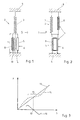
- FIG. 1 shows an adjusting device 1 which acts on a structure 2 in order to deform it, for example.
- the structure 2 is indicated in FIG. 1 by a mechanical spring 3 whose rigidity for the rigidity of the structure 2 is opposite the adjustment by the adjusting device 1.
- Both the adjusting device 1 and the structure 2 are supported at the rear on a common base 4.
- the adjusting device 1 has an actuating element 5, which with a drive signal 6 to a change in length l is drivable in the direction of an arrow 7.
- the change in length The adjustment of the structure 2 with the adjusting device 1 acts on the part of the structure an increasing with the travel restoring force, taking into account the inherent rigidity of the adjusting element 5, the effective change in length l reduced at a given drive signal 6.
- a spring 8 is connected in parallel with negative stiffness.
- the spring 8 has in a zero crossing of its spring characteristic, a negative slope, ie, a negative stiffness, which will be discussed in more detail in connection with Figure 3.
- the negative stiffness of the spring 8 at least partially compensates for the positive stiffness of the structure 2, whereby the progressivity of the restoring forces of the structure 2 is effectively reduced compared to an adjustment with the adjusting device 1.
- the arrow 7 in Figure 1 indicates that the structure 2 is compressed by the adjusting device 1, wherein the adjusting element 5 is loaded on pressure. This is favorable, for example, if the adjusting element 5 is based on a piezoelectric crystal, which is very sensitive. If the adjusting device 1 is to pull apart the structure 2, then a directional deflection 9 for the adjusting element 5 indicated in FIG. 2 is possible.
- an elastic element 10 may be provided, which is connected in parallel to the adjusting element 5 and this is under a compressive bias.
- the arrangement of the spring 8 with negative stiffness in addition to the structure 2 would be possible even with other arrangement according to FIG. This is due to the fact that the force-displacement curve of the spring 8 with negative rigidity in the region of the zero crossing of its spring characteristic with respect to the direction of the travel of the adjusting device 1 is invariant. Taking into account the principle actio equal reaction results from the fact that the spring 8 can be arranged with negative stiffness everywhere where it acts on the actuator 5 relative to the base 4.
- FIG. 3 shows, over the travel s of the adjusting device 1 according to FIGS. 1 and 2, the forces F exerted by the individual components on the adjusting element 5. That is, there are the spring characteristics of these components applied.
- a straight line from the zero point increasing spring characteristic 11 is the spring characteristic of all acting on the actuator 5, increasing with the spring restoring forces, ie in particular of the structure 2, but also including possibly from an elastic member 10 of Figure 1 outgoing restoring forces.
- the spring characteristic 12 is the spring characteristic of the spring 8 with negative rigidity.
- the spring characteristic 12 has a zero crossing 13 with a negative slope. This corresponds to a negative stiffness of the spring 8 in the zero crossing 13. In the superimposition of the spring characteristics 11 and 12 results in the dashed lines reproduced total spring characteristic 14.
- the Monfederkennline 14 has a working range 15 of the travel s, which is arranged symmetrically about the zero crossing 13, a particularly low slope, which is close to zero.
- This small pitch in the working area 15 corresponds to a low overall rigidity of the forces acting on the adjusting element 5. This will reduce the effective length change L minimized by the restoring forces without the restoring forces are reduced on average absolutely.
- the spring 8 has Accordingly, two parts 16 and 17, resulting in changes in the Stellwegs in the direction of arrows 18 and 19 against each other.
- the part 16 of the spring 8 consists of interposition of soft iron intermediate pieces 20 arranged one above the other Permanent magnets 21.
- the same name poles N and S the permanent magnets 21 each to a soft iron intermediate piece 20 on. This will focus the magnetic field lines achieved or the magnetic field, which is bundled in radial direction laterally from the soft iron intermediate pieces 20 exit.
- the soft iron intermediate pieces 20 of the part 16 lie annular soft iron intermediate pieces 22 of the other part 17 across from.
- Adjusting device 1 In the case of the indicated in Figure 6 concrete application example of Adjusting device 1 according to the invention, that of the embodiment corresponds to Figure 1, it is the structure of a adaptive blade tip 24 of a rotor blade 25 for a Helicopter.
- the rotor blade 25 has a passive region 26 and an adjacent active area 27. Between the passive region 26 and the active region 27 is the Adjusting device 1 is arranged.
- the adjusting device 1 supports over a web 28 on a spar 29 of the rotor blade 25 as Base off.
- a tension element 30, which is a tensile strength CFK fiber strand acted upon the actuator 1 an anchor plate 31 at the free end of the blade tip 24.
- the anchor plate 4 in turn acts on a torsion skin 32 on pressure.
- the torsional skin 32 causes in the active area 27 helically wound by an additionally provided there location Fibers a pressure-torsion coupling.
- the Torsionshaut 32 via an elastic intermediate layer 33 with the Holm 29 connected.
- the passive region 26 is the rotor blade 25 constructed in a conventional manner.
- the at the rotation the movable members 30 and 31 and the mass elements the torsional skin 32 occurring centrifugal forces are based in the transition region via the adjusting device 1 and the Torsion skin 32 at the passive region 26 of the rotor blade 25th from.
- the actuator is due to the connection of the tension element 30 claimed only on compressive forces.
- the torsional skin 32 is a Deformation coupling, so that the of the adjusting device producible changes in length essential for the efficiency of Deformation in the active region of the blade tip 24 are.
Landscapes
- Engineering & Computer Science (AREA)
- General Engineering & Computer Science (AREA)
- Mechanical Engineering (AREA)
- Springs (AREA)
- Braking Arrangements (AREA)
Claims (8)
- Dispositif de réglage comportant un élément de réglage dont une variation de la longueur peut être commandée par un signal de commande et sur lequel agit une force de rappel présentant une rigidité positive sur sa course de réglage, caractérisé en ce qu'il est prévu un ressort (8) présentant une rigidité négative (CN) à un passage par zéro (13) de sa courbe caractéristique, afin de compenser au moins en partie la rigidité positive (CP) de la force de rappel, sur une zone de travail (15) de la course de réglage (s), le ressort (8) de rigidité négative (CN) étant couplé en parallèle à l'élément de réglage (5).
- Dispositif de réglage selon la revendication 1, caractérisé en ce que le ressort (8) de rigidité négative (CN) et l'élément de réglage (5) présentent deux points d'action terminaux communs.
- Dispositif de réglage selon l'une des revendications 1 et 2, caractérisé en ce que le passage par zéro (13) de la courbe caractéristique (12) du ressort (8) de rigidité négative (CN) est réglable dans la direction de la course de réglage (s).
- Dispositif de réglage selon l'une des revendications 1 à 3, caractérisé en ce que le ressort (8) de rigidité négative (CN) est un ressort magnétique.
- Dispositif de réglage selon la revendication 4, caractérisé en ce que le ressort magnétique (8) comporte deux parties (16, 17) pouvant coulisser l'une par rapport à l'autre sur la course de ressort (s) et pourvues d'aimants permanents (21, 23).
- Dispositif de réglage selon la revendication 5, caractérisé en ce que les deux parties (16, 17) du ressort magnétique (8) comportent chacune plusieurs aimants permanents (21, 23) montés l'un derrière l'autre dans la direction de la course de ressort (s), entre les aimants permanents (21, 23) étant disposées des pièces intercalaires en fer (20, 22) auxquelles font suite les deux aimants permanents (21, 23) voisins de même polarité (N ou S).
- Dispositif de réglage selon l'une des revendications 1 à 6, caractérisé en ce qu'il est prévu une multiplication ou démultiplication pour la course (s) du ressort (8) de rigidité négative (CN).
- Dispositif de réglage selon l'une des revendications 1 à 7, caractérisé en ce que l'élément de réglage (5) comporte un piézo-cristal, un moyen élastique (10) étant prévu qui place le piézo-cristal sous précontrainte de pression.
Applications Claiming Priority (2)
| Application Number | Priority Date | Filing Date | Title |
|---|---|---|---|
| DE19809544A DE19809544C2 (de) | 1998-03-05 | 1998-03-05 | Stellvorrichtung mit einem Stellelement, auf das eine mit dem Stellweg zunehmende Rückstellkraft einwirkt |
| DE19809544 | 1998-03-05 |
Publications (3)
| Publication Number | Publication Date |
|---|---|
| EP0940601A2 EP0940601A2 (fr) | 1999-09-08 |
| EP0940601A3 EP0940601A3 (fr) | 2003-11-12 |
| EP0940601B1 true EP0940601B1 (fr) | 2005-10-19 |
Family
ID=7859879
Family Applications (1)
| Application Number | Title | Priority Date | Filing Date |
|---|---|---|---|
| EP99103665A Expired - Lifetime EP0940601B1 (fr) | 1998-03-05 | 1999-02-25 | Dispositif de commande avec un élément de commande sur lequel agit une force de réaction proportionnelle au déplacement |
Country Status (2)
| Country | Link |
|---|---|
| EP (1) | EP0940601B1 (fr) |
| DE (2) | DE19809544C2 (fr) |
Families Citing this family (4)
| Publication number | Priority date | Publication date | Assignee | Title |
|---|---|---|---|---|
| JP2002021922A (ja) * | 2000-07-11 | 2002-01-23 | Delta Tooling Co Ltd | 磁気回路を利用した除振機構 |
| DE10148207B4 (de) * | 2001-09-28 | 2010-01-28 | Eads Deutschland Gmbh | Piezoelektrische Klappensteuerung |
| CN105822720A (zh) * | 2016-04-29 | 2016-08-03 | 无锡港盛重型装备有限公司 | 一种电动车减震装置 |
| PL235743B1 (pl) * | 2017-09-01 | 2020-10-19 | Politechnika Poznanska | Amortyzator magnetyczny |
Family Cites Families (4)
| Publication number | Priority date | Publication date | Assignee | Title |
|---|---|---|---|---|
| ATE23298T1 (de) * | 1983-04-11 | 1986-11-15 | Deutsche Forsch Luft Raumfahrt | Federungssystem fuer ein kraftfahrzeug. |
| JPH0884401A (ja) * | 1994-09-12 | 1996-03-26 | Mitsubishi Materials Corp | パンタグラフの接触力の安定化装置 |
| DE19509485C1 (de) * | 1995-03-16 | 1996-05-15 | Daimler Benz Ag | Schwingungsisolator |
| DE19541600C1 (de) * | 1995-11-08 | 1997-07-17 | Deutsche Forsch Luft Raumfahrt | Stromabnehmer für die Energieübertragung zwischen einem Fahrdraht und einem Triebwagen |
-
1998
- 1998-03-05 DE DE19809544A patent/DE19809544C2/de not_active Expired - Fee Related
-
1999
- 1999-02-25 EP EP99103665A patent/EP0940601B1/fr not_active Expired - Lifetime
- 1999-02-25 DE DE59912662T patent/DE59912662D1/de not_active Expired - Fee Related
Also Published As
| Publication number | Publication date |
|---|---|
| DE19809544A1 (de) | 1999-09-09 |
| DE19809544C2 (de) | 2000-04-13 |
| EP0940601A3 (fr) | 2003-11-12 |
| DE59912662D1 (de) | 2006-03-02 |
| EP0940601A2 (fr) | 1999-09-08 |
Similar Documents
| Publication | Publication Date | Title |
|---|---|---|
| EP0799502B1 (fr) | Element d'entrainement ou de reglage a actionnement piezo-electrique | |
| EP1268273B1 (fr) | Dispositif d'actionnement piezo-electrique servant a commander les volets au niveau d'une ailette de rotor d'un helicoptere | |
| DE60205370T2 (de) | Schwingungstilger | |
| EP0127741B1 (fr) | Système de suspension pour un véhicule automobile | |
| EP3867191B1 (fr) | Transducteur de flexion comme actionneur, transducteur de flexion comme capteur, système de transducteur de flexion | |
| EP3610315B1 (fr) | Dispositif de miroirs micromécanique | |
| DE3410473A1 (de) | Federungssystem fuer ein kraftfahrzeug | |
| DE2556924A1 (de) | Lagerloser schwingmotor | |
| EP1927782A1 (fr) | Amortisseur à masse syntonisée actif | |
| WO2007059718A1 (fr) | Element micromecanique deployable | |
| EP2013965A1 (fr) | Moteur piézoélectrique utilisé comme système de propulsion de véhicule, servomoteur et analogue | |
| DE4231734A1 (de) | Piezoelektrische einrichtung | |
| EP1528281A1 (fr) | Amortisseur de vibrations adaptatif | |
| WO2005093286A1 (fr) | Arbre d'equilibrage pour un moteur a plusieurs cylindres en ligne | |
| DE102008042967A1 (de) | Kaskadierte mikromechanische Aktuatorstruktur | |
| EP0940601B1 (fr) | Dispositif de commande avec un élément de commande sur lequel agit une force de réaction proportionnelle au déplacement | |
| WO2017005588A1 (fr) | Dispositif de déviation d'un faisceau laser | |
| EP1535027B1 (fr) | Detecteur de vitesses de rotation | |
| EP0230626B1 (fr) | Dispositif pour régler la rigidité d'un ressort magnétique | |
| WO2008009578A2 (fr) | Moteur électromécanique | |
| DE602004012756T2 (de) | Nichtlineare federkraft-schaltbaugruppe | |
| EP2356705A2 (fr) | Entraînement universel électrique de piézomoteur | |
| EP0504465A1 (fr) | Transducteur fluidique à entraînement piézo-électrique | |
| DE10019226B4 (de) | Elektromechanischer Linearantrieb mit Momentenkompensation | |
| EP3301730A1 (fr) | Convertisseur d'énergie |
Legal Events
| Date | Code | Title | Description |
|---|---|---|---|
| PUAI | Public reference made under article 153(3) epc to a published international application that has entered the european phase |
Free format text: ORIGINAL CODE: 0009012 |
|
| AK | Designated contracting states |
Kind code of ref document: A2 Designated state(s): AT BE CH CY DE DK ES FI FR GB GR IE IT LI LU MC NL PT SE |
|
| AX | Request for extension of the european patent |
Free format text: AL;LT;LV;MK;RO;SI |
|
| PUAL | Search report despatched |
Free format text: ORIGINAL CODE: 0009013 |
|
| AK | Designated contracting states |
Kind code of ref document: A3 Designated state(s): AT BE CH CY DE DK ES FI FR GB GR IE IT LI LU MC NL PT SE |
|
| AX | Request for extension of the european patent |
Extension state: AL LT LV MK RO SI |
|
| RIC1 | Information provided on ipc code assigned before grant |
Ipc: 7G 05G 7/04 B Ipc: 7G 05G 7/16 B Ipc: 7G 05G 5/05 B Ipc: 7F 16F 3/02 A |
|
| 17P | Request for examination filed |
Effective date: 20031103 |
|
| 17Q | First examination report despatched |
Effective date: 20040303 |
|
| AKX | Designation fees paid |
Designated state(s): DE FR GB IT |
|
| GRAP | Despatch of communication of intention to grant a patent |
Free format text: ORIGINAL CODE: EPIDOSNIGR1 |
|
| GRAS | Grant fee paid |
Free format text: ORIGINAL CODE: EPIDOSNIGR3 |
|
| GRAA | (expected) grant |
Free format text: ORIGINAL CODE: 0009210 |
|
| AK | Designated contracting states |
Kind code of ref document: B1 Designated state(s): DE FR GB IT |
|
| REG | Reference to a national code |
Ref country code: GB Ref legal event code: FG4D Free format text: NOT ENGLISH |
|
| GBT | Gb: translation of ep patent filed (gb section 77(6)(a)/1977) |
Effective date: 20060125 |
|
| REF | Corresponds to: |
Ref document number: 59912662 Country of ref document: DE Date of ref document: 20060302 Kind code of ref document: P |
|
| ET | Fr: translation filed | ||
| RAP2 | Party data changed (patent owner data changed or rights of a patent transferred) |
Owner name: DEUTSCHES ZENTRUM FUER LUFT- UND RAUMFAHRT E.V. |
|
| PLBE | No opposition filed within time limit |
Free format text: ORIGINAL CODE: 0009261 |
|
| STAA | Information on the status of an ep patent application or granted ep patent |
Free format text: STATUS: NO OPPOSITION FILED WITHIN TIME LIMIT |
|
| 26N | No opposition filed |
Effective date: 20060720 |
|
| PGFP | Annual fee paid to national office [announced via postgrant information from national office to epo] |
Ref country code: DE Payment date: 20070208 Year of fee payment: 9 |
|
| PGFP | Annual fee paid to national office [announced via postgrant information from national office to epo] |
Ref country code: GB Payment date: 20070221 Year of fee payment: 9 |
|
| PGFP | Annual fee paid to national office [announced via postgrant information from national office to epo] |
Ref country code: IT Payment date: 20070531 Year of fee payment: 9 |
|
| PGFP | Annual fee paid to national office [announced via postgrant information from national office to epo] |
Ref country code: FR Payment date: 20070216 Year of fee payment: 9 |
|
| GBPC | Gb: european patent ceased through non-payment of renewal fee |
Effective date: 20080225 |
|
| REG | Reference to a national code |
Ref country code: FR Ref legal event code: ST Effective date: 20081031 |
|
| PG25 | Lapsed in a contracting state [announced via postgrant information from national office to epo] |
Ref country code: DE Free format text: LAPSE BECAUSE OF NON-PAYMENT OF DUE FEES Effective date: 20080902 |
|
| PG25 | Lapsed in a contracting state [announced via postgrant information from national office to epo] |
Ref country code: FR Free format text: LAPSE BECAUSE OF NON-PAYMENT OF DUE FEES Effective date: 20080229 |
|
| PG25 | Lapsed in a contracting state [announced via postgrant information from national office to epo] |
Ref country code: GB Free format text: LAPSE BECAUSE OF NON-PAYMENT OF DUE FEES Effective date: 20080225 |
|
| PG25 | Lapsed in a contracting state [announced via postgrant information from national office to epo] |
Ref country code: IT Free format text: LAPSE BECAUSE OF NON-PAYMENT OF DUE FEES Effective date: 20080225 |