EP0940655B1 - Sonde de mesure comportant au moins une fibre optique, dispositif de mesure et installation comportant au moins une telle sonde - Google Patents
Sonde de mesure comportant au moins une fibre optique, dispositif de mesure et installation comportant au moins une telle sonde Download PDFInfo
- Publication number
- EP0940655B1 EP0940655B1 EP99410009A EP99410009A EP0940655B1 EP 0940655 B1 EP0940655 B1 EP 0940655B1 EP 99410009 A EP99410009 A EP 99410009A EP 99410009 A EP99410009 A EP 99410009A EP 0940655 B1 EP0940655 B1 EP 0940655B1
- Authority
- EP
- European Patent Office
- Prior art keywords
- optic
- optic fiber
- probe according
- light
- connection
- Prior art date
- Legal status (The legal status is an assumption and is not a legal conclusion. Google has not performed a legal analysis and makes no representation as to the accuracy of the status listed.)
- Expired - Lifetime
Links
Images


Classifications
-
- G—PHYSICS
- G01—MEASURING; TESTING
- G01K—MEASURING TEMPERATURE; MEASURING QUANTITY OF HEAT; THERMALLY-SENSITIVE ELEMENTS NOT OTHERWISE PROVIDED FOR
- G01K11/00—Measuring temperature based upon physical or chemical changes not covered by groups G01K3/00, G01K5/00, G01K7/00 or G01K9/00
- G01K11/32—Measuring temperature based upon physical or chemical changes not covered by groups G01K3/00, G01K5/00, G01K7/00 or G01K9/00 using changes in transmittance, scattering or luminescence in optical fibres
- G01K11/3206—Measuring temperature based upon physical or chemical changes not covered by groups G01K3/00, G01K5/00, G01K7/00 or G01K9/00 using changes in transmittance, scattering or luminescence in optical fibres at discrete locations in the fibre, e.g. using Bragg scattering
- G01K11/3213—Measuring temperature based upon physical or chemical changes not covered by groups G01K3/00, G01K5/00, G01K7/00 or G01K9/00 using changes in transmittance, scattering or luminescence in optical fibres at discrete locations in the fibre, e.g. using Bragg scattering using changes in luminescence, e.g. at the distal end of the fibres
-
- G—PHYSICS
- G01—MEASURING; TESTING
- G01D—MEASURING NOT SPECIALLY ADAPTED FOR A SPECIFIC VARIABLE; ARRANGEMENTS FOR MEASURING TWO OR MORE VARIABLES NOT COVERED IN A SINGLE OTHER SUBCLASS; TARIFF METERING APPARATUS; MEASURING OR TESTING NOT OTHERWISE PROVIDED FOR
- G01D5/00—Mechanical means for transferring the output of a sensing member; Means for converting the output of a sensing member to another variable where the form or nature of the sensing member does not constrain the means for converting; Transducers not specially adapted for a specific variable
- G01D5/26—Mechanical means for transferring the output of a sensing member; Means for converting the output of a sensing member to another variable where the form or nature of the sensing member does not constrain the means for converting; Transducers not specially adapted for a specific variable characterised by optical transfer means, i.e. using infrared, visible, or ultraviolet light
- G01D5/268—Mechanical means for transferring the output of a sensing member; Means for converting the output of a sensing member to another variable where the form or nature of the sensing member does not constrain the means for converting; Transducers not specially adapted for a specific variable characterised by optical transfer means, i.e. using infrared, visible, or ultraviolet light using optical fibres
-
- G—PHYSICS
- G02—OPTICS
- G02B—OPTICAL ELEMENTS, SYSTEMS OR APPARATUS
- G02B6/00—Light guides; Structural details of arrangements comprising light guides and other optical elements, e.g. couplings
- G02B6/24—Coupling light guides
- G02B6/42—Coupling light guides with opto-electronic elements
- G02B6/4201—Packages, e.g. shape, construction, internal or external details
-
- G—PHYSICS
- G02—OPTICS
- G02B—OPTICAL ELEMENTS, SYSTEMS OR APPARATUS
- G02B6/00—Light guides; Structural details of arrangements comprising light guides and other optical elements, e.g. couplings
- G02B6/24—Coupling light guides
- G02B6/42—Coupling light guides with opto-electronic elements
- G02B6/4201—Packages, e.g. shape, construction, internal or external details
- G02B6/4274—Electrical aspects
- G02B6/4277—Protection against electromagnetic interference [EMI], e.g. shielding means
-
- G—PHYSICS
- G02—OPTICS
- G02B—OPTICAL ELEMENTS, SYSTEMS OR APPARATUS
- G02B6/00—Light guides; Structural details of arrangements comprising light guides and other optical elements, e.g. couplings
- G02B6/24—Coupling light guides
- G02B6/42—Coupling light guides with opto-electronic elements
- G02B6/4201—Packages, e.g. shape, construction, internal or external details
- G02B6/4274—Electrical aspects
- G02B6/4284—Electrical aspects of optical modules with disconnectable electrical connectors
-
- G—PHYSICS
- G02—OPTICS
- G02B—OPTICAL ELEMENTS, SYSTEMS OR APPARATUS
- G02B6/00—Light guides; Structural details of arrangements comprising light guides and other optical elements, e.g. couplings
- G02B6/24—Coupling light guides
- G02B6/42—Coupling light guides with opto-electronic elements
- G02B6/4201—Packages, e.g. shape, construction, internal or external details
- G02B6/4246—Bidirectionally operating package structures
Definitions
- Known fiber optic measurement probes generally comprise at least one fiber optic with a first end connected to a sensor and a second end is connected to an electronic processing device.
- an electronic processing device To connect the fibers to the treatment, it is known to use removable optical connectors intended to cooperate with fixed optical or optoelectronic elements connected to the processing circuit.
- optical connectors require careful alignment with other fibers or with optoelectronic elements for maximum signal power coupling luminous circulating in the fibers.
- optical connectors are expensive and bulky and therefore not very compatible with installations that need several measuring points.
- optical connectors may be subject to constraints which can damage the optical links during their installation or handling.
- Document US5107445 describes an example of a fiber optic temperature probe having an optical connector for connecting an optical fiber to an optical head disposed on a printed circuit board for signal processing.
- the object of the invention is a fiber optic measurement probe which can easily be installed, a measuring device and an installation comprising such a probe.
- a fiber optic probe according to the invention is defined by claim 1.
- the probe includes amplification means connected between signal converting means and the first connection means.
- the probe comprises a sensor disposed on said at least one optical fiber and reacting to light signals, light signals from said sensor being representative of a physical quantity to be measured.
- the probe includes storage means for storing calibration or adjustment parameters.
- the signal converting means comprise at least one photo-detector, converting light signals supplied at one end of an optical fiber into signals e.
- the signal converting means comprise at least one transmitter optics to convert electronic signals from the first means of electrical connection in light signals injected at one end of an optical fiber maintained in optical connection with said optical transmitter.
- the temperature sensor disposed at one end at least one optical fiber comprises a luminescent material, a first light signal being sent from converter means to excite said luminescent material and a second light signal being emitted by said material and conveyed through said optical fiber to the signal converting means, said second light signal having a length wave different from the wavelength of the first light signal and a decrease representative of a temperature.
- the probe comprises first and second optical fibers arranged between the sensor and the signal converting means, the first optical fiber conducting the first light signal and the second optical fiber driving the second light signal.
- the probe may include an optical separation system arranged between the fiber optical and signal converting means.
- the probe may include an optical filter disposed between a end of an optical fiber and the signal converting means.
- At least one optical fiber is a plastic optical fiber.
- the optical fiber holding means comprise a piece of positioning of an optical fiber on the signal converting means.
- the optical fiber holding means comprise a guide element.
- converter means comprise at least a light-emitting diode, a photo-detector and fixing means to maintain a first optical fiber in optical connection with said light-emitting diode and a second optical fiber in optical connection with said photo-detector.
- the probe includes fixing means to maintain first three optical fibers in optical connection with three light-emitting diodes and three second optical fibers in optical connection with three photo-detectors.
- the light emitting diodes and the first connection means are arranged on a first printed circuit and the photo-detectors are arranged on a second printed circuit, the second printed circuit being connected electrically to the first printed circuit and positioned substantially orthogonally.
- the probe can include a first insulating coating covering at least part of the electronic circuit and a second conductive coating covering at least part of the first coating.
- the probe is used for the temperature measurement of at least an electrical conductor.
- a fiber optic measuring device comprises processing means signals, a probe as defined above, and second connection means connected to the processing means and intended to cooperate with the first means of connection.
- An installation according to the invention comprises at least one electrical conductor, and at least a probe as defined above connected to said electrical conductor.
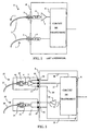
- the optical fiber probes 1 comprise optical fibers 2 associated with optical connectors 3. These optical connectors are removable, they cooperate with optoelectronic devices 4 and 5, connected to a circuit 6 of a device 8 for centralizing measurements.
- the devices optoelectronics may include, in particular a photo-detector 4 for receiving light signals or a light-emitting diode 5 to emit light signals.
- an amplifier 7 is connected between the photo-detector 4 and the processing 6 for amplifying electronic signals representative of light signals.
- intermediate fibers can be used between the connectors optics and optoelectronic devices.
- the optical connection of connectors 3 may not be perfectly realized. Indeed, it sometimes requires specific tools and qualified personnel to adjust the optical alignment of the connectors 3 with the optoelectronic devices 4 and 5. In addition, if this optical coupling is not of good quality, the optical losses are too high and the measurements made by the probes may be erroneous.
- optical connectors Another disadvantage of using fibers with optical connectors concerns the risk of damage to said connectors. Indeed, these probes can undergo all kinds of mechanical or atmospheric constraints which can modify the characteristics of the optical coupling. For example, optical connectors can be soiled, partially clogged or covered with moisture or dust.
- the probe comprises a circuit electronics on which an optical fiber is maintained in optical connection with a device optoelectronic signal converter connected to an electrical connector.
- An end user in this case receives a probe whose optical link part is already made. This user, specializing in particular in electrical installations, will only have to connect electrically the probe without worrying about the optical part.
- the optical link being performed optimally and hermetically protected, external constraints are without effect and the measurements made by the probe are not altered.
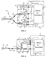
- FIG. 2 shows a measuring device with two fiber optic probes 10 and 11 according to a first embodiment of the invention.
- a first probe 10 includes a circuit electronic 12 such as a printed circuit on which a photo-detector 4 is optically linked to an optical fiber 13 maintained and protected by a holding device 14.
- the circuit 12 comprises a removable electrical connector 15 intended to cooperate with a connector fixed electrical 16 disposed on the device 8.
- the electrical circuit may also include a amplifier 7 connected between the photodetector 4 and the connector 16.
- the connectors 15 and 16 also convey in this embodiment, an electronic measurement signal 17, a reference line 19 and a supply line 18.
- a second probe 11 includes an electronic circuit 12 such as a printed circuit or a wired circuit on which an optical fiber 20 is optically linked to a diode light emitting 21, said diode 21 being maintained and protected by a device holding 14.
- the light emitting diode 21 is connected to the removable connector 15 disposed on circuit 12, said connector 15 being intended to cooperate with a fixed connector 16 disposed on the device 8.
- the connectors 15 and 16 have a connection point to send an electronic signal 22 to the diode 21 and a point for the reference line 19.
- the signal 22 supplied by the processing circuit 6 can be amplified by a circuit amplification 23.
- all of the connector connection points 15 can be grouped on the same connector, and the fibers 13 and 20 can cooperate in a same measurement and be maintained on the same circuit 12.
- Figure 3 shows the diagram of a measuring device and a probe 24 comprising two optical fibers 13 and 20 associated with a sensor 25.
- the two optical fibers are maintained by one end on a circuit 12 in optical connection with converter converters signals 4 and 21, the other end of each fiber being associated with the sensor 25.
- a first fiber 20 is maintained on a circuit 12 in optical connection with the diode light emitting 21 by a first end, the other end being associated with the sensor 25.
- a second optical fiber 13 is maintained on the circuit 12 in optical connection with the photo-detector 4 by a first end, the other end also being associated with the sensor 25.
- the photo-detector 4 is a phototransistor connected to the input of a amplifier 7, the output of which is connected to a removable connector 15.
- Diode 21 is connected to through an amplifier circuit 23 to the connector 15.
- the connector 15 is capable of being associated with a fixed connector 16 of the device 8.
- the processing circuit 6 is connected to the fixed connector 16. It sends signals from control 22 at the diode 21 and receives from the photo-detector 4 measurement signals 17 and return.
- the control signals 22 are converted by the light-emitting diode 21 into first light signal 26 flowing in the first optical fiber 20 to excite the sensor 25.
- a second light signal 27 emitted by the sensor 25 circulates in the second fiber optical 13 to be detected by the photo-detector 4 which converts the second light signal as an electronic signal 17. This signal is amplified by amplifier 7 and supplies the treatment 6 through the electrical connectors 15 and 16.
- optical links being optimally adjusted then the fibers being fixed and maintained, the measurements made by the probes are safe and reliable.
- the probes can be easily installed or replaced by simple electrical connections of the removable connectors 15.
- a storage circuit 28 arranged on circuit 12 allows the storage of adjustment or calibration parameters. So the probes with sensors 25 can be calibrated in the laboratory or on a site specialized during assembly and then be easily used without adjustment in installations industrial.
- the calibration or calibration parameters may relate in particular to continuous shifts, amplitude or distortion responses, attenuations as a function time, delay times, or correlation tables.
- information 32 representative of the parameters of adjustment are provided to said circuit 6.
- the processing circuit 6 can correct and adapt the electronic signals representative of the light signals circulating in the fibers and representative of measurements physical. This information 32 flows through the connectors 15 and 16.
- Figure 4 shows the diagram of a measuring device and a probe comprising a fiber optics 29 in which the first and second light signals 26 and 27 circulate.
- the fiber 29 is connected to the sensor 25 by a first end and the other opposite end is maintained on the circuit 12 by the holding device 14 in optical connection with the diode 21 and the photo-detector 4.
- a separation device 30 comprising a semi-reflective strip is disposed between the end of the fiber 29, the diode 21 and the photo-detector 4 to separate the signals 27 coming from the fiber and the sensor in the direction of the photo-detector 4 light signals 26 going from the diode to the fiber and the sensor.
- the separation device can be a fiber power divider.
- an optical filter 31 is placed in front of the photo-detector 4.
- the filter optical allows signal 27 having a first wavelength to pass and blocks signal 26 having a second wavelength.
- the circuit 12 includes the connector 15 removable which carries the supply lines 18 and reference 19 and the signal 17 of measurement and the signal 22 for controlling the diode 21.
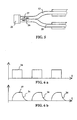
- FIG. 5 A sensor which can be used in probes according to the invention is shown in FIG. 5.
- This sensor comprises a material 33 which reacts to the light of the first signal 26 which it receives. Then, or at the same time, the second light signal 27 is emitted by said material 33.
- the second light signal is representative of a physical quantity to be measured. In particular, in a particular embodiment, this physical quantity is a temperature.
- the second signal has a length wave different from the wavelength of the first signal.
- the light intensity of the second signal decreases almost exponentially as a function of time when the first signal stops illuminating the material 33.
- a decrease 34 of the second signal is representative of the temperature of said material.
- FIG. 6a illustrates the light amplitude of a first signal 26 illuminating the material 33 and FIG. 6b illustrates a second signal 27 emitted by said material 33.
- the processing circuit 6 determines a value of the temperature at which the material 33 is found as a function of the decrease 34 of signal 27 converted into electronic signal 17.
- Figure 7 shows the diagram of a fiber optic probe for three measurement channels.
- the measurement channels comprising first optical fibers 20a, 20b, 20c optically connect sensors 25a, 25b, 25c, light emitting diodes 21a, 21b, 21c and seconds optical fibers 13a, 13b, 13c connect the sensors 25a, 25b, 25c to photo-detectors represented by photodiodes 4a, 4b, 4c.
- the six optical fibers 20a, 20b, 20c, 13a, 13b and 13c are held on the circuit 12 by holding devices 14.
- the three light-emitting diodes 21a, 21b, 21c are connected to the removable electrical connector 15 to receive control signals 22a, 22b and 22c respectively.
- Photodiodes 4a, 4b, 4c in optical connection with the second fibers 13a, 13b, 13c respectively are connected to amplifiers respectively 7a, 7b, 7c.
- each amplifier The gains of each amplifier are determined by resistors 36a, 36b, 36c connected between the output and the inverting input of each amplifier respectively 7a, 7b, 7c.
- Amplifier outputs are connected to connector 15 to provide signals 17a, 17b, 17c, representative of the measurements made by each sensor respectively 25a, 25b, 25c.
- the connector 15 also provides a reference line 19 and two V + and V- supply lines for supplying amplifiers.
- the sensors 25a, 25b, 25c are in particular temperature sensors functioning for example as a sensor of FIG. 5 with a fluorescent or luminescent material.
- the probe of FIG. 7 is advantageously used for the temperature measurement of an electrical installation comprising conductors 37a, 37b, 37c.
- Optical fibers having a high dielectric strength, probes according to FIG. 7 can be used in installations with high electrical voltages, in particular low voltages, medium voltages or high voltages.
- Figure 8 shows part of a three-way probe according to Figure 7.
- the circuit 12 comprises two printed circuits 38 and 39 arranged so substantially orthogonal.
- a first printed circuit 38 includes the diodes 21a, 21b, 21c and connector 15 and a second printed circuit 39 comprises the photo-detectors 4a, 4b, 4c with the amplifiers 7a, 7b, 7c.
- the two circuits prints are linked mechanically and electrically. This provision reduces advantageously the volume of the probe and also reduces the connection surface with the measuring device.
- FIG. 9 A side view in section of a probe according to FIG. 8 is represented in FIG. 9.
- the first optical fibers 20a, 20b, 20c are put in an orifice provided on the light emitting diodes 21a, 21b, 21c.
- Figure 9 shows a fiber 20a introduced into a diode 21a.
- the second fibers 13a, 13b, 13c are connected optically with the photo-detectors 4a, 4b, 4c respectively.
- the fiber 13a is placed opposite the photo-detector 4a.
- an optical filter 31 disposed between the second fiber 13a and the photodetector 4a filters light signals in order to let the signals from the sensor and stop the signals generated by the light emitting diodes.
- the device 14 for holding the optical fiber comprises a part 40 for fixing and positioning the optical fibers.
- Fibers optics can also be bonded to the part 40 by casting a material 41 in a recess 42 of said part 40 receiving the fibers.
- a holding device 14 comprises a part base 43, and guide elements 45 of optical fibers.
- a probe comprises a first insulating coating 47 covering electronic components of circuit 12 and a second conductive coating 48 covering the first insulating coating (see FIG. 9).
- the second coating conductor has the function of electromagnetic shielding.
- the materials constituting the coatings are polymers.
- circuits 12 or connectors 15 have locking devices 46 for fixing the removable connectors 15 on fixed connectors 16.
- the electrical circuit 12 can be a wired circuit, a impregnated circuit or, for example, a circuit for mounting components on the surface.
Landscapes
- Physics & Mathematics (AREA)
- General Physics & Mathematics (AREA)
- Optics & Photonics (AREA)
- Electromagnetism (AREA)
- Measuring Temperature Or Quantity Of Heat (AREA)
- Investigating Or Analysing Materials By Optical Means (AREA)
- Optical Couplings Of Light Guides (AREA)
- Arrangements For Transmission Of Measured Signals (AREA)
Description
- au moins une fibre optique,
- au moins un capteur de température disposé à une extrémité d'au moins une fibre optique, et
- au moins un circuit électronique comportant des premiers moyens de connexion électrique.
- la figure 1 montre un schéma de raccordement de sondes à fibres optiques de type connu,
- la figure 2 montre un premier schéma de sondes et de dispositifs à fibre optique selon un premier mode de réalisation de l'invention,
- la figure 3 montre un second schéma de sondes et de dispositifs à fibres optiques selon un second mode de réalisation de l'invention,
- la figure 4 montre un troisième schéma de sonde et de dispositif à fibres optiques selon un troisième mode de réalisation de l'invention,
- la figure 5 montre un capteur pouvant être associé à une sonde selon des modes de réalisation de l'invention,
- les figures 6a et 6b montrent des signaux pouvant circuler dans des fibres optiques de sondes selon des modes de réalisation de l'invention,
- la figure 7 montre un schéma d'une sonde selon un mode de réalisation de l'invention à trois voies de mesure,
- la figure 8 montre une vue d'une sonde selon le schéma de la figure 7 à trois voies,
- la figure 9 montre une vue de côté d'une sonde selon un mode de réalisation de l'invention,
- la figure 10 montre une vue d'une sonde selon le schéma de la figure 7 comportant des moyens de maintien améliorés.
Claims (19)
- Sonde de mesure à fibre optique comportant :caractérisée en ce que les premiers moyens de connexion sont des moyens de connexion amovibles,au moins une fibre optique (2, 13, 20),au moins un capteur de température (25, 25a-c) disposé à une extrémité d'au moins une fibre optique (13, 20, 29), etau moins un circuit électronique (12) comportant des premiers moyens (15) de connexion électrique,
et en ce qu'elle comporte :des moyens convertisseurs (4, 21, 4a, 4b, 4c, 21a, 21b, 21c) de signaux connectés aux premiers moyens de connexion amovibles et destinés à faire une interface entre des signaux lumineux (26, 27) véhiculés par au moins une fibre optique associée audit capteur de température et des signaux électroniques (17, 22) destinés à circuler dans lesdits premiers moyens de connexion, etdes moyens de maintien (14, 40-45) de fibre optique pour maintenir de manière fixe ladite au moins une fibre optique associée audit capteur de température en liaison optique avec lesdits moyens convertisseurs. - Sonde selon la revendication 1, caractérisée en ce qu'elle comporte des moyens d'amplification (7, 23) connectés entre des moyens convertisseurs (4, 21) de signaux et les premiers moyens de connexion (15).
- Sonde selon l'une des revendications 1 ou 2, caractérisée en ce qu'elle comporte des moyens de mémorisation (28) pour mémoriser des paramètres de calibration ou de réglage.
- Sonde selon l'une quelconque des revendications 1 à 3, caractérisée en ce que les moyens convertisseurs de signaux (4, 21) comportent au moins un photo-détecteur (4, 4a, 4b, 4c) convertissant des signaux lumineux fournis à une extrémité d'une fibre optique (13) en signaux électroniques (17).
- Sonde selon l'une quelconque des revendications 1 à 4, caractérisée en ce que les moyens convertisseurs de signaux comportent au moins un émetteur optique (21, 21a, 21 b, 21c) pour convertir des signaux électroniques (22) provenant des premiers moyens de connexion (15) électriques en signaux lumineux (26) injectés à une extrémité d'une fibre optique (20) maintenue en liaison optique avec ledit émetteur optique.
- Sonde selon l'une quelconque des revendications 1 à 5, caractérisée en ce que le capteur de température (25, 25a-c) disposé à une extrémité d'au moins une fibre optique (13, 20, 29) comporte un matériau luminescent (33), un premier signal lumineux (26) étant envoyé depuis des moyens convertisseurs pour exciter ledit matériau luminescent et un second signal (27) lumineux étant émis par ledit matériau et véhiculé à travers ladite fibre optique vers les moyens convertisseurs de signaux, ledit second signal lumineux (27) ayant une longueur d'onde différente de la longueur d'onde du premier signal lumineux et une décroissance (34) représentative d'une température.
- Sonde selon la revendication 6, caractérisée en ce qu'elle comporte une première et une seconde fibres optiques (20, 13) disposées entre le capteur (25, 25a-c) et les moyens convertisseurs de signaux (4, 21), la première fibre optique 20 conduisant le premier signal lumineux (26) et la seconde fibre optique (13) conduisant le second signal lumineux (27).
- Sonde selon l'une quelconque des revendications 1 à 6, caractérisée en ce qu'elle comporte un système optique de séparation (30) disposé entre la fibre optique (29) et les moyens convertisseurs de signaux.
- Sonde selon l'une quelconque des revendications 1 à 8, caractérisée en ce qu'elle comporte un filtre optique (31) disposé entre une extrémité d'une fibre optique (29, 13, 13a-c) et les moyens convertisseurs de signaux (4, 4a-c).
- Sonde selon l'une quelconque des revendications 1 à 9 caractérisée en ce que ladite au moins une fibre optique (13, 19, 20) est une fibre optique en matière plastique.
- Sonde selon l'une quelconque des revendications 1 à 10, caractérisée en ce que les moyens de maintien (14) de fibre optique comportent une pièce de positionnement d'une fibre optique sur les moyens convertisseurs de signaux (4, 21).
- Sonde selon l'une quelconque des revendications 1 à 11, caractérisée en ce que les moyens de maintien (14) de fibre optique comportent un élément de guidage (45).
- Sonde selon l'une quelconque des revendications à 7 et 10 à 12, caractérisée en ce qu'elle comporte des moyens convertisseurs comportant au moins une diode (21, 21a-c) électroluminescente, un photo-détecteur (4, 4a-c) et des moyens de fixation (14) pour maintenir une première fibre optique (20, 20a-c) en liaison optique avec ladite diode électroluminescente et une seconde fibre optique (13, 13a-c) en liaison optique avec ledit photo-détecteur.
- Sonde selon l'une des revendications 12 ou 13, caractérisée en ce qu'elle comporte des moyens de fixation pour maintenir trois premières fibres optiques (20a, 20b, 20c) en liaison optique avec trois diodes électroluminescentes (21a, 21b, 21c) et trois secondes fibres optiques (13a, 13b, 13c) en liaison optique avec trois photo-détecteurs (4a, 4b, 4c).
- Sonde selon l'une quelconque des revendications 13 ou 14, caractérisée en ce que les diodes électroluminescentes et les premiers moyens de connexion sont disposés sur un premier circuit imprimé (38) et que les photo-détecteurs sont disposés sur un second circuit imprimé (39), le second circuit imprimé étant relié électriquement au premier circuit imprimé et positionné sensiblement orthogonalement.
- Sonde selon l'une quelconque des revendications 1 à 15, caractérisée en ce qu'elle comporte un premier enrobage isolant (47) couvrant au moins une partie du circuit électronique (12) et un second enrobage (48) conducteur couvrant au moins une partie du premier enrobage.
- Sonde selon l'une quelconque des revendications 1 à 16, caractérisée en ce qu'elle est utilisée pour la mesure de température d'au moins un conducteur électrique (37a-c).
- Dispositif de mesure à fibre optique comportant des moyens de traitement de signaux (6) caractérisé en ce qu'il comporte au moins une sonde selon l'une quelconque des revendications 1 à 17, et des seconds moyens de connexion connectés audits moyens de traitement et destinés à coopérer avec les premiers moyens de connexion (15).
- Installation comportant au moins un conducteur électrique caractérisée en ce qu'elle comporte au moins une sonde selon l'une quelconque des revendications 1 à 17 reliée audit au moins un conducteur électrique.
Applications Claiming Priority (2)
| Application Number | Priority Date | Filing Date | Title |
|---|---|---|---|
| FR9803001A FR2775774B1 (fr) | 1998-03-06 | 1998-03-06 | Sonde de mesure comportant au moins une fibre optique, dispositif de mesure et installation comportant au moins une telle sonde |
| FR9803001 | 1998-03-06 |
Publications (2)
| Publication Number | Publication Date |
|---|---|
| EP0940655A1 EP0940655A1 (fr) | 1999-09-08 |
| EP0940655B1 true EP0940655B1 (fr) | 2004-01-28 |
Family
ID=9523932
Family Applications (1)
| Application Number | Title | Priority Date | Filing Date |
|---|---|---|---|
| EP99410009A Expired - Lifetime EP0940655B1 (fr) | 1998-03-06 | 1999-02-17 | Sonde de mesure comportant au moins une fibre optique, dispositif de mesure et installation comportant au moins une telle sonde |
Country Status (7)
| Country | Link |
|---|---|
| US (1) | US6204915B1 (fr) |
| EP (1) | EP0940655B1 (fr) |
| JP (1) | JP2000205968A (fr) |
| CN (1) | CN1138995C (fr) |
| DE (1) | DE69914391T2 (fr) |
| ES (1) | ES2213998T3 (fr) |
| FR (1) | FR2775774B1 (fr) |
Families Citing this family (16)
| Publication number | Priority date | Publication date | Assignee | Title |
|---|---|---|---|---|
| US6909821B2 (en) * | 1999-12-31 | 2005-06-21 | Pirelli Cavi E Sistemi S.P.A. | Network for distributing signals to a plurality of users |
| FR2818830B1 (fr) | 2000-12-22 | 2003-02-07 | Schneider Electric Ind Sa | Dispositif et procede de traitement de signal et appareil electrique comportant un tel dispositif |
| JP2002340698A (ja) * | 2001-05-11 | 2002-11-27 | Ohkura Electric Co Ltd | 積分球型光ファイバー温度計 |
| FR2836559B1 (fr) * | 2002-02-28 | 2004-06-04 | Schneider Electric Ind Sa | Dispositif de couplage optique, sonde optique et dispositif de communication comportant un tel dispositif de couplage |
| US7315000B2 (en) * | 2003-07-27 | 2008-01-01 | Sandisk Il Ltd. | Electronic module with dual connectivity |
| US7188997B2 (en) * | 2005-01-21 | 2007-03-13 | Eaton Corporation | Apparatus and method for detecting hot spots in an electric power conductor |
| CN1297084C (zh) * | 2005-01-24 | 2007-01-24 | 东南大学 | 集成光电二极管的微波探针测试装置 |
| JP5340628B2 (ja) * | 2008-04-21 | 2013-11-13 | アズビル株式会社 | 蛍光温度センサ |
| JP5676852B2 (ja) * | 2009-03-10 | 2015-02-25 | アズビル株式会社 | 蛍光温度センサ |
| US8422008B2 (en) * | 2010-09-29 | 2013-04-16 | General Electric Company | Electrical machine component monitoring system and method |
| CN102759368B (zh) * | 2011-04-25 | 2014-11-26 | 上海市计量测试技术研究院 | 光导管光电转换脉冲计数计时器 |
| GB2508368B (en) * | 2012-11-29 | 2018-08-08 | Lein Applied Diagnostics Ltd | Optical measurement apparatus and method of manufacturing the same |
| DE102014204371A1 (de) * | 2014-03-11 | 2014-11-20 | Siemens Aktiengesellschaft | Verfahren zum Betreiben eines Geräts zur Erfassung einer physikalischen oder chemischen Größe |
| FR3026179B1 (fr) * | 2014-09-19 | 2018-02-16 | Sc2N | Sonde de mesure comportant un element sensible |
| CN106441627A (zh) * | 2016-08-23 | 2017-02-22 | 南京铁道职业技术学院 | 一种基于铁路隧道通信光缆的温度监测系统 |
| CN118129939A (zh) * | 2024-05-06 | 2024-06-04 | 应急管理部沈阳消防研究所 | 一种荧光光纤测温光路耦合及光电解调模块 |
Family Cites Families (7)
| Publication number | Priority date | Publication date | Assignee | Title |
|---|---|---|---|---|
| JPS5838904A (ja) * | 1981-09-01 | 1983-03-07 | Matsushita Electric Ind Co Ltd | 光検出装置 |
| JPS63212910A (ja) * | 1987-03-02 | 1988-09-05 | Toshiba Corp | 光素子と光フアイバの結合方法 |
| JPS63253910A (ja) * | 1987-04-10 | 1988-10-20 | Toshiba Corp | 光伝送装置 |
| US5107445A (en) * | 1990-12-04 | 1992-04-21 | Luxtron Corporation | Modular luminescence-based measuring system using fast digital signal processing |
| DE9308118U1 (de) * | 1993-05-29 | 1993-08-26 | Kabelwerke Reinshagen Gmbh, 42369 Wuppertal | Faseroptischer Sensor |
| DE9308117U1 (de) | 1993-05-29 | 1993-07-29 | Tel-Da Gesellschaft für Telefon- und Datentechnik mbH, 68519 Viernheim | Bausatz für Steckverbindungen im EDV-Bereich |
| DE9400896U1 (de) * | 1994-01-20 | 1994-03-03 | Fa. Carl Zeiss, 89520 Heidenheim | Strahlungs- und Empfangsvorrichtung |
-
1998
- 1998-03-06 FR FR9803001A patent/FR2775774B1/fr not_active Expired - Fee Related
-
1999
- 1999-02-17 ES ES99410009T patent/ES2213998T3/es not_active Expired - Lifetime
- 1999-02-17 US US09/251,422 patent/US6204915B1/en not_active Expired - Lifetime
- 1999-02-17 EP EP99410009A patent/EP0940655B1/fr not_active Expired - Lifetime
- 1999-02-17 DE DE69914391T patent/DE69914391T2/de not_active Expired - Lifetime
- 1999-03-04 CN CNB991024893A patent/CN1138995C/zh not_active Expired - Fee Related
- 1999-03-08 JP JP11060624A patent/JP2000205968A/ja active Pending
Also Published As
| Publication number | Publication date |
|---|---|
| ES2213998T3 (es) | 2004-09-01 |
| DE69914391T2 (de) | 2004-11-25 |
| DE69914391D1 (de) | 2004-03-04 |
| CN1234513A (zh) | 1999-11-10 |
| JP2000205968A (ja) | 2000-07-28 |
| FR2775774B1 (fr) | 2000-04-14 |
| EP0940655A1 (fr) | 1999-09-08 |
| US6204915B1 (en) | 2001-03-20 |
| CN1138995C (zh) | 2004-02-18 |
| FR2775774A1 (fr) | 1999-09-10 |
Similar Documents
| Publication | Publication Date | Title |
|---|---|---|
| EP0940655A1 (fr) | Sonde de mesure comportant au moins une fibre optique, dispositif de mesure et installation comportant au moins une telle sonde | |
| JP3698393B2 (ja) | 光送受信モジュールの構造及びその製法 | |
| US5271079A (en) | Light mixing device with fiber optic output | |
| US6722793B2 (en) | Optical bidirectional transceiver module having a pin element with integrated WDM filter | |
| FR2740282A1 (fr) | Appareil de mesure d'une propriete de ligne de transmission optique et appareil de transmission a multiplexage de longueur d'onde optique | |
| JPH0545904B2 (fr) | ||
| EP0234309A2 (fr) | Procédé et dispositif pour mesurer à distance la distribution d'un paramètre physicochimique dans un milieu | |
| EP1215777A3 (fr) | Dispositif de stabilisation de la longueur d'onde et module laser à longueur d'onde stabilisé | |
| US6922231B1 (en) | Receiver optical sub-assembly with diagnostic signal | |
| US20040104336A1 (en) | Fiber optic sensing system | |
| FR2475826A1 (fr) | Dispositif de declenchement d'alarme pour une insuffisance du niveau de transmission, pour module recepteur d'un systeme de transmission sur fibre optique | |
| US6948865B2 (en) | Optical module and method of manufacturing the same | |
| US20050100349A1 (en) | Optical receiver | |
| FR2875646A1 (fr) | Embase de connecteur a contacts electriques et optiques | |
| US6487327B1 (en) | Optical fiber connector monitor apparatus | |
| FR2604252A1 (fr) | Capteur de deplacement et proximite a fibres optiques | |
| US7221813B2 (en) | Signal acquisition probing and voltage measurement systems using an electro-optical cavity | |
| FR2654840A1 (fr) | Tete optique integrable sur un circuit hybride. | |
| KR20020063577A (ko) | 농도 측정 장치 | |
| US7366428B2 (en) | Optical receiver | |
| US20050109921A1 (en) | Alignment method for photoelectric element of photoelectric device with optical fiber | |
| RU155668U1 (ru) | Оптоэлектронный модуль | |
| US7187187B2 (en) | Signal acquisition probing system using a micro-cavity laser | |
| EP0859225A2 (fr) | Procédé et dispositif de mesure du taux de réflexion d'éléments à fibre optique | |
| US20060204182A1 (en) | Apparatus and method for coupling a fiber to a photodetector |
Legal Events
| Date | Code | Title | Description |
|---|---|---|---|
| PUAI | Public reference made under article 153(3) epc to a published international application that has entered the european phase |
Free format text: ORIGINAL CODE: 0009012 |
|
| AK | Designated contracting states |
Kind code of ref document: A1 Designated state(s): CH DE ES GB IT LI SE |
|
| AX | Request for extension of the european patent |
Free format text: AL;LT;LV;MK;RO;SI |
|
| 17P | Request for examination filed |
Effective date: 19991222 |
|
| RAP1 | Party data changed (applicant data changed or rights of an application transferred) |
Owner name: SCHNEIDER ELECTRIC INDUSTRIES SA |
|
| AKX | Designation fees paid |
Free format text: CH DE ES GB IT LI SE |
|
| RAP1 | Party data changed (applicant data changed or rights of an application transferred) |
Owner name: SCHNEIDER ELECTRIC INDUSTRIES SAS |
|
| 17Q | First examination report despatched |
Effective date: 20030218 |
|
| GRAP | Despatch of communication of intention to grant a patent |
Free format text: ORIGINAL CODE: EPIDOSNIGR1 |
|
| GRAS | Grant fee paid |
Free format text: ORIGINAL CODE: EPIDOSNIGR3 |
|
| GRAA | (expected) grant |
Free format text: ORIGINAL CODE: 0009210 |
|
| AK | Designated contracting states |
Kind code of ref document: B1 Designated state(s): CH DE ES GB IT LI SE |
|
| REG | Reference to a national code |
Ref country code: GB Ref legal event code: FG4D Free format text: NOT ENGLISH |
|
| REG | Reference to a national code |
Ref country code: CH Ref legal event code: EP |
|
| REF | Corresponds to: |
Ref document number: 69914391 Country of ref document: DE Date of ref document: 20040304 Kind code of ref document: P |
|
| GBT | Gb: translation of ep patent filed (gb section 77(6)(a)/1977) |
Effective date: 20040315 |
|
| REG | Reference to a national code |
Ref country code: SE Ref legal event code: TRGR |
|
| REG | Reference to a national code |
Ref country code: ES Ref legal event code: FG2A Ref document number: 2213998 Country of ref document: ES Kind code of ref document: T3 |
|
| PLBE | No opposition filed within time limit |
Free format text: ORIGINAL CODE: 0009261 |
|
| STAA | Information on the status of an ep patent application or granted ep patent |
Free format text: STATUS: NO OPPOSITION FILED WITHIN TIME LIMIT |
|
| 26N | No opposition filed |
Effective date: 20041029 |
|
| PGFP | Annual fee paid to national office [announced via postgrant information from national office to epo] |
Ref country code: IT Payment date: 20120222 Year of fee payment: 14 |
|
| PGFP | Annual fee paid to national office [announced via postgrant information from national office to epo] |
Ref country code: SE Payment date: 20130212 Year of fee payment: 15 Ref country code: CH Payment date: 20130212 Year of fee payment: 15 Ref country code: ES Payment date: 20130215 Year of fee payment: 15 Ref country code: DE Payment date: 20130211 Year of fee payment: 15 Ref country code: GB Payment date: 20130213 Year of fee payment: 15 |
|
| REG | Reference to a national code |
Ref country code: DE Ref legal event code: R119 Ref document number: 69914391 Country of ref document: DE |
|
| REG | Reference to a national code |
Ref country code: CH Ref legal event code: PL Ref country code: SE Ref legal event code: EUG |
|
| GBPC | Gb: european patent ceased through non-payment of renewal fee |
Effective date: 20140217 |
|
| PG25 | Lapsed in a contracting state [announced via postgrant information from national office to epo] |
Ref country code: CH Free format text: LAPSE BECAUSE OF NON-PAYMENT OF DUE FEES Effective date: 20140228 Ref country code: LI Free format text: LAPSE BECAUSE OF NON-PAYMENT OF DUE FEES Effective date: 20140228 |
|
| REG | Reference to a national code |
Ref country code: DE Ref legal event code: R119 Ref document number: 69914391 Country of ref document: DE Effective date: 20140902 |
|
| PG25 | Lapsed in a contracting state [announced via postgrant information from national office to epo] |
Ref country code: SE Free format text: LAPSE BECAUSE OF NON-PAYMENT OF DUE FEES Effective date: 20140218 |
|
| PG25 | Lapsed in a contracting state [announced via postgrant information from national office to epo] |
Ref country code: GB Free format text: LAPSE BECAUSE OF NON-PAYMENT OF DUE FEES Effective date: 20140217 Ref country code: DE Free format text: LAPSE BECAUSE OF NON-PAYMENT OF DUE FEES Effective date: 20140902 |
|
| REG | Reference to a national code |
Ref country code: ES Ref legal event code: FD2A Effective date: 20150401 |
|
| PG25 | Lapsed in a contracting state [announced via postgrant information from national office to epo] |
Ref country code: ES Free format text: LAPSE BECAUSE OF NON-PAYMENT OF DUE FEES Effective date: 20140218 |
|
| PG25 | Lapsed in a contracting state [announced via postgrant information from national office to epo] |
Ref country code: IT Free format text: LAPSE BECAUSE OF NON-PAYMENT OF DUE FEES Effective date: 20140217 |