EP0940671B1 - Vorrichtung, Verfahren und Aufzeichnungsmedium zur Video-Inspektion - Google Patents
Vorrichtung, Verfahren und Aufzeichnungsmedium zur Video-Inspektion Download PDFInfo
- Publication number
- EP0940671B1 EP0940671B1 EP98122701A EP98122701A EP0940671B1 EP 0940671 B1 EP0940671 B1 EP 0940671B1 EP 98122701 A EP98122701 A EP 98122701A EP 98122701 A EP98122701 A EP 98122701A EP 0940671 B1 EP0940671 B1 EP 0940671B1
- Authority
- EP
- European Patent Office
- Prior art keywords
- video
- image
- frame
- inspection
- periodic pattern
- Prior art date
- Legal status (The legal status is an assumption and is not a legal conclusion. Google has not performed a legal analysis and makes no representation as to the accuracy of the status listed.)
- Expired - Lifetime
Links
Images



Classifications
-
- G—PHYSICS
- G06—COMPUTING OR CALCULATING; COUNTING
- G06T—IMAGE DATA PROCESSING OR GENERATION, IN GENERAL
- G06T7/00—Image analysis
- G06T7/40—Analysis of texture
- G06T7/41—Analysis of texture based on statistical description of texture
- G06T7/42—Analysis of texture based on statistical description of texture using transform domain methods
-
- G—PHYSICS
- G06—COMPUTING OR CALCULATING; COUNTING
- G06V—IMAGE OR VIDEO RECOGNITION OR UNDERSTANDING
- G06V10/00—Arrangements for image or video recognition or understanding
- G06V10/40—Extraction of image or video features
- G06V10/42—Global feature extraction by analysis of the whole pattern, e.g. using frequency domain transformations or autocorrelation
- G06V10/431—Frequency domain transformation; Autocorrelation
-
- G—PHYSICS
- G06—COMPUTING OR CALCULATING; COUNTING
- G06V—IMAGE OR VIDEO RECOGNITION OR UNDERSTANDING
- G06V20/00—Scenes; Scene-specific elements
- G06V20/40—Scenes; Scene-specific elements in video content
-
- G—PHYSICS
- G06—COMPUTING OR CALCULATING; COUNTING
- G06T—IMAGE DATA PROCESSING OR GENERATION, IN GENERAL
- G06T2207/00—Indexing scheme for image analysis or image enhancement
- G06T2207/10—Image acquisition modality
- G06T2207/10016—Video; Image sequence
-
- G—PHYSICS
- G06—COMPUTING OR CALCULATING; COUNTING
- G06T—IMAGE DATA PROCESSING OR GENERATION, IN GENERAL
- G06T2207/00—Indexing scheme for image analysis or image enhancement
- G06T2207/20—Special algorithmic details
- G06T2207/20021—Dividing image into blocks, subimages or windows
-
- G—PHYSICS
- G06—COMPUTING OR CALCULATING; COUNTING
- G06T—IMAGE DATA PROCESSING OR GENERATION, IN GENERAL
- G06T2207/00—Indexing scheme for image analysis or image enhancement
- G06T2207/20—Special algorithmic details
- G06T2207/20048—Transform domain processing
- G06T2207/20056—Discrete and fast Fourier transform, [DFT, FFT]
-
- H—ELECTRICITY
- H04—ELECTRIC COMMUNICATION TECHNIQUE
- H04N—PICTORIAL COMMUNICATION, e.g. TELEVISION
- H04N17/00—Diagnosis, testing or measuring for television systems or their details
Definitions
- the present invention relates to a device for monitoring images for specific types of patterns by analyzing video such as television pictures; more specifically the present invention relates to a device, method and recording medium for video inspection suitable for detecting images which contain periodic patterns of high contrast such as striping, checker, concentric, radial, or swirl patterns, covering more than a predetermined area.
- images containing periodic patterns such as striping, checker, concentric, radial, or swirl patterns having high contrast, may induce seizures when viewed by a photosensitive person.
- Detecting images containing such patterns as described above by visually checking takes much time.
- the inspector(s) may also potentially be affected in his/her health by viewing video including the type of pattern forms mentioned above. Furthermore, this may cause a problem in that different inspectors may have different judgments concerning the same subject matter due to the nature of personal error or variation.
- U.S. Patent No. 5,636,296 discloses a video image analysis system that utilizes a plurality of processors to process either a plurality of input image frames concurrently or a plurality of processing items for a single input frame.
- U.S. Patent No. 5,191,413 discloses an image display system for identifying and eliminating undesired motion shaking of fast moving image components.
- a digital processor scans for interfield differences that extend vertically and coherently over several pels, which are larger than intrafield detail. In the areas of detected motion, only one field will contain pels unaltered from their original capture state. With respect to remaining fields, an operator can modify each of the pels in accordance with the teachings of this reference.
- An object of the present invention is to provide a device, method and recording medium for video inspection capable of automatically detecting in video pictures high-contrast images having specific patterns.
- images with patterns having a specific from that may affect the viewing individuals may be automatically detected from within a video stream, by performing image analysis on each image in a frame in a video subject to be inspected with respect to both the contrast and spatial frequency thereof, and detecting frames having large image area displayed in which the intensity of the contrast and the frequency range of the peak values of the spatial frequency are out of allowable tolerance ranges respectively.
- the decisive results of decision means i.e., the indication of presence or absence of some specific class of image patterns may be output, thereby according to the result output, the specific class of image patterns may be edited or removed by means of image editor later.
- the images may be automatically substituted by other replacing images previously prepared, so that no human attendant is required to inspect any potentially provocative images. Therefore not only viewers but also video production staff will be protected from potentially harmful images.
- the output video from a video display device, video playback device, and TV game machine may be inspected.
- the processing time will be shortened by carrying out the image analysis block by block in comparison to the image analysis of the entire frame at once.
- the probability of onset of photosensitive attacks among viewers will be minimized by inspecting for image patterns in the video which are known to cause such photosensitive attacks prior to the on-air broadcast of a program.
- these potentially harmful image patterns are automatically checked without human attendance, allowing faster and quicker inspection than the inspection of the prior art by human inspectors, and no deviation of inspection accuracy due to personal error of variation.
- the present invention requires no inspector to be attendant at inspection, allowing production cost to be reduced and workers to be protected from potentially harmful video at the same time.
- the video inspecting device of the present invention enables to checking for and warning of possibly harmful images which may induce photosensitive attacks among viewers.
- Fig. 1A-1D Some examples of pattern forms to be detected in images are shown in Fig. 1A-1D.
- Fig. 1A shows a vertical stripe pattern.
- Fig. 1B shows a checker pattern.
- Fig. 1C shows a concentric pattern; and
- Fig. 1D shows a whorl pattern. All of these patterns are locally periodic (repetitive) in at least one direction.
- the inventor(s) of the present invention have found that, when performing frequency analysis, for example, by the Fast Fourier Transformation (FFT), there is an acute peak in that portion at a particular spatial frequency (first condition).
- the inventors also have found that a high contrast image is characterized by large alternating current energy (second condition).
- FFT Fast Fourier Transformation
- an entire image is divided into a plurality of small blocks, then it is determined whether the image in each block satisfies the two conditions described above. Thereafter the image will be judged to belong to the specified class of images if the ratio between the area occupied by the blocks satisfying both the first and second conditions as described above and the area of the entire image exceeds a predefined value.
- FIG. 2 A system architecture of the video inspection device using such video inspection method as described above is shown in Fig. 2.
- reference numeral 1 designates an analog/digital (A/D) converter for analog to digital conversion.
- Reference numeral 2 designates a frame buffer for temporary storage of one screenful (frame) of image data (brightness data in this embodiment).
- Reference numeral 3 designates a contrast detector for analyzing the image data to determine whether or not its contrast is within an allowable tolerance range.
- Reference numeral 4 designates a frequency analyzer, which analyzes frequency within each divided block according to the image data stored in the frame buffer 2 if the result from contrast detector 3 is out of range.
- Reference numeral 5 designates a peak seeker, which determines whether or not the peak indicated by the frequency analysis results of each block falls within into a predefined frequency band, characterizing the class of image patterns to be detected.
- Reference numeral 6 designates a decision circuit for summing, based on the results of each block obtained from the peak seeker 5, the area (or the number) of blocks containing an acute peak (blocks determined by the peak seeker 5 in which the peak value is within a predefined frequency range) to compute the ratio between the summed area and the screen size (or the ratio between the number of blocks having a peak and the total number of blocks constituting the full-screen image). If this ratio is out of range, the image represented by the image data in the frame buffer 2 is determined to belong to the class of images to be detected.
- the result output circuit 7 outputs the result from the decision circuit 6.
- Various output modes such as simple alarm of a light, display of character messages, output of the frame number along with the result through a printer, and so on, may be employed.
- Reference numeral 8 is a frame delay, which delays the input video signal so as to synchronize it with the image processing system which consists of circuits from 1 through 6.
- Reference numeral 9 is a substitute pattern generator which generates image patterns for replacement. Non-volatile memory such as read-only memory (ROM) may be used for the substitute pattern generator 9.
- ROM read-only memory
- Reference numeral 10 designates a switch, which outputs image signals of the image pattern generated by the substitute pattern generator 9, instead of outputting video signals derived from the frame delay 8, i.e., the image to be inspected, in the case in which the decision circuit 6 detects one of the pattern forms exemplified in Fig. 1A-1D, in order to replace patterns such as are shown in Fig. 1A-1D contained in the video signal with a replacement image pattern.
- the signal from the decision circuit 6 indicating the presence of one of the sought class of patterns is not generated, video signals from the frame delay 8 will be output.
- the system as mentioned above may be alternatively embodied by using for example an image processor or a personal computer.
- the process performed in the contrast detector 3, the frequency analyzer 4, the peak seeker 5, the decision circuit 6, the frame delay 8, and the switch 10 may be written as a software program to be executed by a CPU to provide the functionality of the circuitry as mentioned above.
- the above circuitry may be constructed with digital circuits as well.
- Video signals are inputted to the device through a video input means such as a connector (not shown) in the form of analog signals comprised of frames of images, such as NTSC signals.
- the A/D converter 1 converts from analog input video signals to digital video signals to input to the frame buffer 2.
- an entire image (frame) is divided into small blocks of M (in the abscissa axis direction ) by N (in the ordinate axis direction). Thereafter the blocks are processed one by one, and the next frame will be captured at the time when all processing on every block in one frame is complete.
- the variance ⁇ 2 of brightness of all pixels (picture elements) in one small block is determined by using the following expression: wherein I ij refers to the brightness of a pixel located in the position (i,j) in that block. This corresponds to the total energy of alternating current components of the image in that block. If this value exceeds a predefined threshold value ⁇ 1, i.e., if this value is out of allowable tolerance range, then the contrast detector 3 determines that this small block is a high contrast block, and sends the image data for that block to the succeeding stage, the frequency analyzer 4.
- the sum of edge intensities obtained by passing through a differential filter such as a sobel filter may be divided by the number of pixels constituting edges to obtain an "average edge intensity" to compare with a threshold.
- the image data transferred from the contrast detector 3 is subjected to a Fourier transform which resolves it into spatial frequency components in order to derive an energy for each spatial frequency.
- the result F ⁇ of the Fourier transform of the image data of each block is comprised of a real number part R ⁇ F ⁇ ⁇ and an imaginary number part I ⁇ F ⁇ ⁇ , where ⁇ and ⁇ indicate spatial frequencies in the horizontal direction and the vertical direction, respectively.
- E ⁇ (R ⁇ F ⁇ ⁇ ) 2 + (I ⁇ F ⁇ ⁇ ) 2
- the spatial frequency spectrum in each respective block is examined to determine whether or not it contains an acute peak in the predefined frequency range f1 - f2.
- a peak is defined to be acute if it satisfies either or both of the following conditions:
- the total area of the blocks having an acute peak is determined. If the ratio between the total area of these blocks and the area of the complete image (frame) exceeds a predefined threshold value ⁇ 4, then that image is determined to be an image containing one of the class of respective patterns to be identified (pattern forms exemplified in Fig. 1A-1D).
- the result output circuit 7 displays the status of detection according to the results of the decision circuit 6, i.e., an image pattern of the class to be identified has been detected.
- An ON/OFF signal indicating existence or absence of the class of patterns to be detected causes the switch 10 to change connection. If an image pattern of the class to be detected is determined to be present, the substitute pattern image generated by the substitute pattern generator 9 will be output so as to replace detected pattern images such as those shown in Fig. 1A-1D. Since the video signals (frame images) are delayed by the frame delay 8 by at least the period of time necessary from the input to the decision, the replacement of pattern images may be executed at the time of detection.
- the frequency analyzer 4 if an original image is shrunk to 1/2, 1/4, 1/8, ... and Fourier Transform is applied thereon, the spatial frequency range which may be inspected is changeable. Furthermore, the Fourier Transform can be processed in a shorter time because of the reduced amount of image data to be processed. For the frequency analysis, image analyzing methods such as Wavelet Transform, Multiple Resolution Fourier Transform, or Hough Transform may be used instead of the Fourier Transform.
- the thresholds ⁇ 1, ⁇ 2, ⁇ 3, ⁇ 4, f1 and f2 as mentioned above, which are conditions for the pattern detection, such as the contrast intensity for example, may be fixed. Alternatively, these thresholds may be set adjustably by manually entering parameter data from an input device (not shown) such as a numeric keypad.
- the second embodiment of the present invention implementing the visual inspection device by an image processing device will be described below in greater detail.
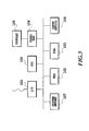
- the system arrangement of the second embodiment of the present invention is shown in Fig. 3.
- Well known information processing devices such as personal computers can be used for the image processing device.
- the processing procedure (software program, see Fig. 4) is different from that above.
- the software program for video inspection is written in a language readable by a computer, and installed to the image processing device via a recording medium such as floppy diskette or CD-ROM.
- a CPU 100 controls the entire system, under the control of the operating system (OS) stored in the system memory 107 and hard disk drive 102.
- the interface 101 is also known as a graphics board, which sequentially captures video signals in the form of NTSC standard on frame-by-frame basis, to convert to digital signals that the CPU 100 can process.
- Various video signal generators such as television receiver sets, video cameras, video cassette recorders, and TV game machines can be used.
- the hard disk drive 102 stores, in addition to the operating system, some software programs for video inspection according to the present invention, and some software programs for creating and editing moving pictures.
- the floppy diskette drive 103 accepts a floppy diskette, and reads software program stored thereon for video inspection as mentioned above under the control of the CPU 100.
- the video RAM 104 stores one frame of image data. Writing image data into video RAM 104 is performed by the CPU 100, image data will be read out therefrom by a controller (not shown) in a display 105 for display on the screen of the display 105.
- the input device 106 includes a mouse and a keyboard.
- the input device 106 is used for inputting various commands to the CPU 100 and miscellaneous information for execution of the software programs.
- the system memory 107 includes ROM and RAM.
- the system memory 107 is used as storage for storing part of the OS, as well as working space for storing data required by the OS and software programs, and storage of programs executed by the CPU 100.
- the video inspection process executed in this system arrangement will be now described below in greater detail, with reference to Fig. 4.
- the process shown in Fig. 4 is written in a programming language executable by the CPU 100 and installed in the hard disk drive 102. By instructing through the input device 106, the process is loaded into the system memory 107 and executed by the CPU 100.
- the software program which is shown in Fig. 4 is decomposed into several process routines known in the prior art. It is to be noted that one of those skilled in the art will be able to write such a software program with or without exact source codes written in a particular programming language.
- the CPU 100 captures a frame image (one screenful image data) from the I/O 101 to write into the system memory 107 (step S100).
- the CPU 100 divides the frame image stored in the system memory 107 into, for example, eight blocks.
- the CPU 100 picks up first block of the image data to compute the contrast intensity according to expression (1). It is determined whether or not the contrast intensity is within an allowable tolerance range (step S130). If the contrast is out of range, the process proceeds from step S130 to step S140 to perform frequency analysis.
- step S130 If the contrast falls within the range, the process proceeds from step S130 through S170 to S110 to perform contrast computation of second block.
- step S140 first block of image data is used for frequency analysis. It is determined whether or not the peak energy value obtained from expression (2) falls into the frequency range (tolerance range) indicative of the class of image patterns exemplified in Fig. 1A-1D.
- step S150 the process proceeds from step S150 through S170 to S110 to perform contrast computation of the second block. If not, the frame being inspected is determined to contain part of one of the class of image patterns exemplified in Fig. 1A-1D. Then the area of the first block is stored in the system memory 107 for accumulation (summation) of areas (step S160).
- step S170 the process proceeds from step S170 to S110 to perform contrast inspection and frequency inspection of the second block. If the second block is determined to be out of range in both inspections, the area is accumulated. Then the process repeats those steps of video inspection for all remaining blocks (YES decision in step S170), the CPU 100 computes the ratio between the accumulated surface area and the frame area to determine whether the ratio falls within a tolerance range (step S180). If the ratio is out of range, i.e., frame subject to be inspected is determined to contain any of the class of image patterns exemplified Fig. 1A-1D, the CPU 100 modifies the frame image stored in the system memory 107 (frame image loaded from the I/O 101).
- the modification may be either replacement thereof with a substitute image pattern previously created and stored in the HDD 102, or replacement with a warning frame indicating that one of the class of image patterns exemplified in Fig. 1A-1D lies in that frame, or elimination of the input frame image in the I/O 101.
- the modified frame image will be stored in the HDD 102 for example in the MPEG (Motion Picture Expert Group) file format for moving video. If the frame image being inspected is determined not to contain any one of the class of image patterns exemplified in Fig. 1A-1D (i.e., YES decision in step S180), the frame image loaded from the I/O 101 and stored in the system memory 107 will be written into HDD 102. By repeating the process above to the end of input video (looping step S100 to S210), videos (moving pictures) made of a plurality of frames (still images) may be inspected.
- MPEG Motion Picture Expert Group
- inspected video may be output to external devices by means of a floppy diskette, magneto-optical disks (MO disks) or communication interface (not shown) if desired, since images are stored in the system.
- a floppy diskette magneto-optical disks (MO disks) or communication interface (not shown) if desired, since images are stored in the system.
- MO disks magneto-optical disks
- communication interface not shown
Landscapes
- Engineering & Computer Science (AREA)
- Physics & Mathematics (AREA)
- General Physics & Mathematics (AREA)
- Theoretical Computer Science (AREA)
- Multimedia (AREA)
- Computer Vision & Pattern Recognition (AREA)
- Probability & Statistics with Applications (AREA)
- Image Analysis (AREA)
- Testing, Inspecting, Measuring Of Stereoscopic Televisions And Televisions (AREA)
- Picture Signal Circuits (AREA)
- Closed-Circuit Television Systems (AREA)
- Investigating Materials By The Use Of Optical Means Adapted For Particular Applications (AREA)
- Image Processing (AREA)
Claims (17)
- Videoüberwachungsvorrichtung enthaltend:dadurch gekennzeichnet, dassein Eingabemittel (1, 2; 101) zum Eingeben eines Videos zur Überwachung; undein Bildanalysemittel (3, 4; 100) zum Analysieren des Bildes in jedem Rahmen des eingegebenen Bildes bezüglich seiner Ortsfrequenz;
das Bildanalysemittel (3, 4; 100) ferner ausgelegt ist zum Analysieren jedes Rahmens des Bildes bezüglich seines Kontrasts, und
die Videoüberwachungsvorrichtung ferner enthält:ein Bildprozessormittel (5, 6; 100, 107) zum Berechnen, in Übereinstimmung mit dem Ergebnis der Bildanalyse, einer Beziehung zwischen dem gesamten Bildbereich und dem Teil des Bildes, in welchem der Kontrast und der Spitzenwert des Frequenzbereichs der Ortsfrequenz außerhalb eines ersten und zweiten zulässigen Toleranzbereichs jeweils liegen; undein Entscheidungsmittel (6; 100) zum Bestimmen, dass das Bild ein periodisches Muster von hohem Kontrast enthält, wenn die berechnete Beziehung nicht innerhalb eines dritten zulässigen Toleranzbereichs liegt. - Videoüberwachungsvorrichtung nach Anspruch 1, ferner mit:einem Ausgabemittel (7; 100) zum Ausgeben des Bestimmungsergebnisses von dem Entscheidungsmittel (6; 100).
- Videoüberwachungsvorrichtung nach Anspruch 1, ferner mit:einem Mittel (8, 9, 10; 100) zum Ersetzen des Bildes, das ein periodisches Muster von hohem Kontrast enthält, durch ein Ersatzbild, wenn das Entscheidungsmittel (6; 100) bestimmt, dass das analysierte Bild ein periodisches Muster von hohem Kontrast enthält.
- Videoüberwachungsvorrichtung nach Anspruch 1, ferner mit:einem Mittel (100) zum Beseitigen des Bildes, das ein periodisches Muster von hohem Kontrast enthält, wenn das Entscheidungsmittel (6; 100) bestimmt, dass das analysierte Bild ein periodisches Muster von hohem Kontrast enthält.
- Videoüberwachungsvorrichtung nach Anspruch 1, wobei die Videoüberwachungsvorrichtung ausgelegt ist zum Empfangen eines Videos, das von einer Videoanzeigenvorrichtung als das Video zur Überwachung ausgegeben wird.
- Videoüberwachungsvorrichtung nach Anspruch 1, wobei die Videoüberwachungsvorrichtung ausgelegt ist zum Empfangen eines Videos, das von einer Videowiedergabevorrichtung als das Video zur Überwachung ausgegeben wird.
- Videoüberwachungsvorrichtung nach Anspruch 1, wobei die Videoüberwachungsvorrichtung ausgelegt ist zum Empfangen eines Videos, das von einem Spielautomaten als das Video zur Überwachung ausgegeben wird.
- Videoüberwachungsvorrichtung nach Anspruch 1, wobei das Bildanalysemittel (3, 4; 100) ausgelegt ist zum Durchführen der Bildanalyse für eine Mehrzahl von Blöcken des Rahmens, das Bildprozessormittel (5, 6; 100) ausgelegt ist zum Bestimmen, ob (i) jedes der Ergebnisse der Bildanalyse innerhalb des ersten und zweiten zulässigen Toleranzbereichs liegt, und (ii) die Beziehung zwischen dem Gesamtbereich der Blöcke, die als nicht innerhalb der zulässigen Bereiche liegend bestimmt worden sind, und dem Gesamtbereich des Rahmens außerhalb des dritten zulässigen Toleranzbereichs liegt.
- Videoüberwachungsverfahren mit:dadurch gekennzeichnet, dasseinem Eingeben (S100) eines Videos zur Überwachung; undeinem Analysieren (S110, S120, S130, S140, S150) jedes Rahmenbildes des eingegebenen Videos bezüglich seiner Ortsfrequenz;
der Analyseschritt ferner ein Analysieren jedes Rahmenbildes bezüglich dessen Kontrast enthält;
und das Verfahren ferner aufweist:ein Berechnen (S160, S170), gemäß dem Ergebnis des Bildanalyseschritts, einer Beziehung zwischen dem gesamten Bildbereich und dem Teil des Bildes, in welchem der Kontrast und der Spitzenwert des Frequenzbereichs der Ortsfrequenz außerhalb des ersten und zweiten zulässigen Toleranzbereichs jeweils liegen; undein Bestimmen (S180), dass das Bild ein periodisches Muster von hohem Kontrast enthält, wenn die berechnete Beziehung nicht innerhalb eines dritten zulässigen Toleranzbereichs liegt. - Videoüberwachungsverfahren nach Anspruch 9, ferner mit
einem Ausgeben des Ergebnisses der Bestimmung von dem Bestimmungsschritt (S180). - Videoüberwachungsverfahren nach Anspruch 9, ferner mit
einem Ersetzen (S190) des Bildes, das ein periodisches Muster von hohem Kontrast enthält, durch ein anderes vorbereitetes Ersatzbild, wenn das Bild, das ein periodisches Muster von hohem Kontrast enthält, detektiert wird. - Videoüberwachungsverfahren nach Anspruch 9, ferner mit
einem Eliminieren (S190) des Bildes, das ein periodisches Muster von hohem Kontrast enthält, wenn das Bild, das ein periodisches Muster von hohem Kontrast enthält, detektiert wird. - Videoüberwachungsverfahren nach Anspruch 9, ferner mit
einem Eingeben (S100) eines Videos, das von einer Videoanzeigenvorrichtung als das Video zur Überwachung ausgegeben wird. - Videoüberwachungsvorrichtung nach Anspruch 9, ferner mit
einem Eingeben (S100) eines Videos, das von einer Videowiedergabevorrichtung als das Video zur Überwachung ausgegeben wird. - Videoüberwachungsverfahren nach Anspruch 9, ferner mit
einem Eingeben (S100) eines Videos, das von einem Spielautomaten als das Video zur Überwachung ausgegeben wird. - Videoüberwachungsverfahren nach Anspruch 9, ferner mit
einem Teilen des Rahmens in eine Mehrzahl von Blöcken,
einem Durchführen der Bildanalyse für jeden der Blöcke;
einem Bestimmen, ob jedes der Ergebnisse der Bildanalyse innerhalb des ersten und zweiten zulässigen Toleranzbereich liegt;
einem Berechnen der Beziehung zwischen dem Gesamtbereich der Blöcke, die als nicht innerhalb der zulässigen Toleranzbereiche liegend bestimmt worden sind, und dem Gesamtbereich des Rahmens, und
einem Bestimmen, ob die Beziehung außerhalb des dritten zulässigen Toleranzbereichs liegt. - Aufzeichnungsmedium (107, 103, 107) zum Integrieren in eine Videoüberwachungsvorrichtung, wobei das Aufzeichnungsmedium ein Programm speichert, das Anweisungen enthält, die, wenn von einem Computer (100) gelesen, das Verfahren nach einem der Ansprüche 9 bis 16 durchführen.
Applications Claiming Priority (2)
| Application Number | Priority Date | Filing Date | Title |
|---|---|---|---|
| JP10049805A JP2898269B1 (ja) | 1998-03-02 | 1998-03-02 | 映像検査装置、方法および記録媒体 |
| JP4980598 | 1998-03-02 |
Publications (2)
| Publication Number | Publication Date |
|---|---|
| EP0940671A1 EP0940671A1 (de) | 1999-09-08 |
| EP0940671B1 true EP0940671B1 (de) | 2005-08-10 |
Family
ID=12841367
Family Applications (1)
| Application Number | Title | Priority Date | Filing Date |
|---|---|---|---|
| EP98122701A Expired - Lifetime EP0940671B1 (de) | 1998-03-02 | 1998-11-30 | Vorrichtung, Verfahren und Aufzeichnungsmedium zur Video-Inspektion |
Country Status (5)
| Country | Link |
|---|---|
| US (1) | US6408089B1 (de) |
| EP (1) | EP0940671B1 (de) |
| JP (1) | JP2898269B1 (de) |
| CA (1) | CA2254615C (de) |
| DE (1) | DE69831130T2 (de) |
Families Citing this family (14)
| Publication number | Priority date | Publication date | Assignee | Title |
|---|---|---|---|---|
| JP3098736B2 (ja) * | 1998-04-15 | 2000-10-16 | 日本放送協会 | 映像再生制御装置および記憶媒体 |
| US7773112B2 (en) * | 2002-08-20 | 2010-08-10 | Tektronix, Inc. | Automatic measurement of video parameters |
| JP4933782B2 (ja) * | 2006-01-17 | 2012-05-16 | 日本放送協会 | フリッカ映像検出装置、フリッカ映像検出プログラム、映像表示装置及びフリッカ検出方法 |
| JP4580347B2 (ja) * | 2006-01-17 | 2010-11-10 | 財団法人エヌエイチケイエンジニアリングサービス | フリッカ映像変換装置、そのプログラム及びその方法、並びに、映像表示装置 |
| JP4870990B2 (ja) * | 2006-01-20 | 2012-02-08 | 日本放送協会 | 映像分析装置、視覚刺激危険度判定プログラム及び映像分析システム |
| JP2007235195A (ja) * | 2006-02-27 | 2007-09-13 | Canon Inc | 画像記録装置及び画像表示方法 |
| JP5058002B2 (ja) * | 2008-01-21 | 2012-10-24 | 株式会社豊田中央研究所 | 物体検出装置 |
| JP2009195512A (ja) * | 2008-02-22 | 2009-09-03 | Fujifilm Corp | 放射線画像処理装置 |
| JP2013055619A (ja) * | 2011-09-06 | 2013-03-21 | Sharp Corp | 立体画像情報処理装置、立体画像情報処理方法、立体画像処理プログラムおよびプログラムを記録した記録媒体 |
| JP6540220B2 (ja) * | 2015-05-15 | 2019-07-10 | 日本電気株式会社 | 画像処理装置、画像処理方法、および、画像処理プログラム |
| KR20180102933A (ko) * | 2017-03-08 | 2018-09-18 | 삼성전자주식회사 | Ui를 인식하는 디스플레이 장치 및 그 디스플레이 장치의 제어 방법 |
| JP7212542B2 (ja) * | 2018-03-20 | 2023-01-25 | ファナック株式会社 | Lcd表示器及び診断システム |
| EP4226639A1 (de) | 2020-10-07 | 2023-08-16 | Telefonaktiebolaget LM Ericsson (publ) | System und verfahren zur minimierung von wiederholten blitzen in streaming-medieninhalten |
| CN112330632B (zh) * | 2020-11-05 | 2023-05-02 | 绍兴聚量数据技术有限公司 | 一种基于对抗生成网络的数码相片相机指纹攻击检测方法 |
Family Cites Families (9)
| Publication number | Priority date | Publication date | Assignee | Title |
|---|---|---|---|---|
| US5191413A (en) * | 1990-11-01 | 1993-03-02 | International Business Machines | System and method for eliminating interlace motion artifacts in captured digital video data |
| JP2757668B2 (ja) | 1992-03-11 | 1998-05-25 | 国際電信電話株式会社 | 画像解析装置 |
| JPH0730796A (ja) * | 1993-07-14 | 1995-01-31 | Sony Corp | ビデオ信号追従処理システム |
| IL108974A (en) * | 1994-03-14 | 1999-11-30 | Orbotech Ltd | Device and method for testing a display panel |
| JP2999679B2 (ja) * | 1994-11-30 | 2000-01-17 | 大日本スクリーン製造株式会社 | パターン欠陥検査装置 |
| JPH09312859A (ja) * | 1996-05-23 | 1997-12-02 | Sony Corp | カラー表示装置の画質測定装置及び画質測定方法 |
| US6014183A (en) * | 1997-08-06 | 2000-01-11 | Imagine Products, Inc. | Method and apparatus for detecting scene changes in a digital video stream |
| JPH11102429A (ja) * | 1997-09-05 | 1999-04-13 | Mitsubishi Heavy Ind Ltd | 外観検査装置用の記録/再生装置およびその記録/再生方法 |
| US6173071B1 (en) * | 1997-12-16 | 2001-01-09 | Harold Wasserman | Apparatus and method for processing video data in automatic optical inspection |
-
1998
- 1998-03-02 JP JP10049805A patent/JP2898269B1/ja not_active Expired - Lifetime
- 1998-11-30 DE DE69831130T patent/DE69831130T2/de not_active Expired - Lifetime
- 1998-11-30 CA CA002254615A patent/CA2254615C/en not_active Expired - Fee Related
- 1998-11-30 EP EP98122701A patent/EP0940671B1/de not_active Expired - Lifetime
- 1998-11-30 US US09/201,868 patent/US6408089B1/en not_active Expired - Lifetime
Also Published As
| Publication number | Publication date |
|---|---|
| JP2898269B1 (ja) | 1999-05-31 |
| JPH11252592A (ja) | 1999-09-17 |
| CA2254615C (en) | 2008-05-27 |
| EP0940671A1 (de) | 1999-09-08 |
| US6408089B1 (en) | 2002-06-18 |
| CA2254615A1 (en) | 1999-09-02 |
| DE69831130T2 (de) | 2006-06-01 |
| DE69831130D1 (de) | 2005-09-15 |
Similar Documents
| Publication | Publication Date | Title |
|---|---|---|
| EP0940671B1 (de) | Vorrichtung, Verfahren und Aufzeichnungsmedium zur Video-Inspektion | |
| US5351201A (en) | Method and apparatus for automatic performance evaluation of electronic display devices | |
| EP0720114A2 (de) | Verfahren und Gerät zur Detektion und Interpretation von Untertiteln in digitalen Videosignalen | |
| JPH01109249A (ja) | 部品の表面の亀裂の確認および判定をする方法および装置 | |
| JPH08315113A (ja) | 発塵・発煙の検出方法 | |
| US6999621B2 (en) | Text discrimination method and related apparatus | |
| EP0961275B1 (de) | Ein Videowiedergabesteuerungsgerät und ein Speicherverfahren | |
| Dosselmann et al. | A prototype no-reference video quality system | |
| JP3788586B2 (ja) | パターン検査装置および方法 | |
| JP2004007246A (ja) | 画像処理システム、画像処理方法、画像処理プログラム | |
| KR100817989B1 (ko) | 특징 영상 검출 방법, 영상 상위 검출 방법 및 장치 | |
| JP2769036B2 (ja) | 架空線の自動点検方法 | |
| JPH06333193A (ja) | 移動体検出方法 | |
| JP2865442B2 (ja) | 監視画像の変化領域抽出方法 | |
| JP3454979B2 (ja) | 異常状態検出方法および異常状態検出装置 | |
| US20060126136A1 (en) | Image inspecting apparatus, image inspecting method, control program and computer-readable storage medium | |
| JP4459945B2 (ja) | 抽出色範囲設定方法 | |
| JP3038176B2 (ja) | パターンマッチングによる検査装置 | |
| JP4481319B2 (ja) | データ設定装置 | |
| JPH0360313A (ja) | 架空線点検用画像処理装置 | |
| JPH09190533A (ja) | 車両検知装置 | |
| JP2004084498A (ja) | エンジン評価装置及び方法 | |
| JP2564737B2 (ja) | 自動磁粉探傷装置 | |
| JPH04200084A (ja) | 画像監視装置 | |
| JP2002191045A (ja) | 異常状態検出方法および異常状態検出装置 |
Legal Events
| Date | Code | Title | Description |
|---|---|---|---|
| PUAI | Public reference made under article 153(3) epc to a published international application that has entered the european phase |
Free format text: ORIGINAL CODE: 0009012 |
|
| AK | Designated contracting states |
Kind code of ref document: A1 Designated state(s): DE FR GB |
|
| AX | Request for extension of the european patent |
Free format text: AL;LT;LV;MK;RO;SI |
|
| 17P | Request for examination filed |
Effective date: 19991027 |
|
| AKX | Designation fees paid |
Free format text: DE FR GB |
|
| 17Q | First examination report despatched |
Effective date: 20041029 |
|
| GRAP | Despatch of communication of intention to grant a patent |
Free format text: ORIGINAL CODE: EPIDOSNIGR1 |
|
| GRAS | Grant fee paid |
Free format text: ORIGINAL CODE: EPIDOSNIGR3 |
|
| GRAA | (expected) grant |
Free format text: ORIGINAL CODE: 0009210 |
|
| AK | Designated contracting states |
Kind code of ref document: B1 Designated state(s): DE FR GB |
|
| REG | Reference to a national code |
Ref country code: GB Ref legal event code: FG4D |
|
| REF | Corresponds to: |
Ref document number: 69831130 Country of ref document: DE Date of ref document: 20050915 Kind code of ref document: P |
|
| ET | Fr: translation filed | ||
| PLBE | No opposition filed within time limit |
Free format text: ORIGINAL CODE: 0009261 |
|
| STAA | Information on the status of an ep patent application or granted ep patent |
Free format text: STATUS: NO OPPOSITION FILED WITHIN TIME LIMIT |
|
| 26N | No opposition filed |
Effective date: 20060511 |
|
| PGFP | Annual fee paid to national office [announced via postgrant information from national office to epo] |
Ref country code: DE Payment date: 20131127 Year of fee payment: 16 Ref country code: FR Payment date: 20131108 Year of fee payment: 16 |
|
| PGFP | Annual fee paid to national office [announced via postgrant information from national office to epo] |
Ref country code: GB Payment date: 20141126 Year of fee payment: 17 |
|
| REG | Reference to a national code |
Ref country code: DE Ref legal event code: R119 Ref document number: 69831130 Country of ref document: DE |
|
| REG | Reference to a national code |
Ref country code: FR Ref legal event code: ST Effective date: 20150731 |
|
| PG25 | Lapsed in a contracting state [announced via postgrant information from national office to epo] |
Ref country code: DE Free format text: LAPSE BECAUSE OF NON-PAYMENT OF DUE FEES Effective date: 20150602 |
|
| PG25 | Lapsed in a contracting state [announced via postgrant information from national office to epo] |
Ref country code: FR Free format text: LAPSE BECAUSE OF NON-PAYMENT OF DUE FEES Effective date: 20141201 |
|
| GBPC | Gb: european patent ceased through non-payment of renewal fee |
Effective date: 20151130 |
|
| PG25 | Lapsed in a contracting state [announced via postgrant information from national office to epo] |
Ref country code: GB Free format text: LAPSE BECAUSE OF NON-PAYMENT OF DUE FEES Effective date: 20151130 |