EP0940696A1 - Einlegungsvorrichtung zum Einlegen eines langgestreckten Schutzprofils oberhalb eines in einer Verlegenut verlegten Kabels - Google Patents
Einlegungsvorrichtung zum Einlegen eines langgestreckten Schutzprofils oberhalb eines in einer Verlegenut verlegten Kabels Download PDFInfo
- Publication number
- EP0940696A1 EP0940696A1 EP98121105A EP98121105A EP0940696A1 EP 0940696 A1 EP0940696 A1 EP 0940696A1 EP 98121105 A EP98121105 A EP 98121105A EP 98121105 A EP98121105 A EP 98121105A EP 0940696 A1 EP0940696 A1 EP 0940696A1
- Authority
- EP
- European Patent Office
- Prior art keywords
- protective profile
- insertion device
- wound
- drum
- profile
- Prior art date
- Legal status (The legal status is an assumption and is not a legal conclusion. Google has not performed a legal analysis and makes no representation as to the accuracy of the status listed.)
- Granted
Links
- 230000001681 protective effect Effects 0.000 claims abstract description 57
- 238000003780 insertion Methods 0.000 claims description 35
- 230000037431 insertion Effects 0.000 claims description 35
- 239000013307 optical fiber Substances 0.000 claims description 11
- 230000008961 swelling Effects 0.000 claims description 9
- 239000004033 plastic Substances 0.000 claims description 5
- 229920003023 plastic Polymers 0.000 claims description 5
- 229920001903 high density polyethylene Polymers 0.000 claims description 4
- 239000004700 high-density polyethylene Substances 0.000 claims description 4
- 238000000034 method Methods 0.000 claims description 4
- 239000003795 chemical substances by application Substances 0.000 claims description 3
- 239000003365 glass fiber Substances 0.000 claims description 3
- 239000000463 material Substances 0.000 claims description 3
- 238000013016 damping Methods 0.000 claims description 2
- 150000001875 compounds Chemical class 0.000 claims 2
- VEXZGXHMUGYJMC-UHFFFAOYSA-M Chloride anion Chemical compound [Cl-] VEXZGXHMUGYJMC-UHFFFAOYSA-M 0.000 claims 1
- 229920000728 polyester Polymers 0.000 claims 1
- 238000009434 installation Methods 0.000 description 16
- 239000000945 filler Substances 0.000 description 8
- 239000010410 layer Substances 0.000 description 8
- 239000002184 metal Substances 0.000 description 5
- 229910052751 metal Inorganic materials 0.000 description 5
- 239000004576 sand Substances 0.000 description 4
- XLYOFNOQVPJJNP-UHFFFAOYSA-N water Substances O XLYOFNOQVPJJNP-UHFFFAOYSA-N 0.000 description 4
- 239000004020 conductor Substances 0.000 description 3
- 239000000835 fiber Substances 0.000 description 3
- 238000004804 winding Methods 0.000 description 3
- 239000004698 Polyethylene Substances 0.000 description 2
- 239000010426 asphalt Substances 0.000 description 2
- 230000005540 biological transmission Effects 0.000 description 2
- 229920000573 polyethylene Polymers 0.000 description 2
- 239000011241 protective layer Substances 0.000 description 2
- RYGMFSIKBFXOCR-UHFFFAOYSA-N Copper Chemical compound [Cu] RYGMFSIKBFXOCR-UHFFFAOYSA-N 0.000 description 1
- 241001295925 Gegenes Species 0.000 description 1
- -1 Polyethylene Polymers 0.000 description 1
- 239000004760 aramid Substances 0.000 description 1
- 229920003235 aromatic polyamide Polymers 0.000 description 1
- 238000005452 bending Methods 0.000 description 1
- 230000001413 cellular effect Effects 0.000 description 1
- 229910052802 copper Inorganic materials 0.000 description 1
- 239000010949 copper Substances 0.000 description 1
- 238000013461 design Methods 0.000 description 1
- 230000000694 effects Effects 0.000 description 1
- 238000009422 external insulation Methods 0.000 description 1
- 238000001125 extrusion Methods 0.000 description 1
- 238000012544 monitoring process Methods 0.000 description 1
- 230000003287 optical effect Effects 0.000 description 1
- 230000000149 penetrating effect Effects 0.000 description 1
- 239000004814 polyurethane Substances 0.000 description 1
- 230000001105 regulatory effect Effects 0.000 description 1
- 239000002990 reinforced plastic Substances 0.000 description 1
- 230000002787 reinforcement Effects 0.000 description 1
- 230000002522 swelling effect Effects 0.000 description 1
- 238000012549 training Methods 0.000 description 1
Images


Classifications
-
- E—FIXED CONSTRUCTIONS
- E01—CONSTRUCTION OF ROADS, RAILWAYS, OR BRIDGES
- E01F—ADDITIONAL WORK, SUCH AS EQUIPPING ROADS OR THE CONSTRUCTION OF PLATFORMS, HELICOPTER LANDING STAGES, SIGNS, SNOW FENCES, OR THE LIKE
- E01F11/00—Road engineering aspects of Embedding pads or other sensitive devices in paving or other road surfaces, e.g. traffic detectors, vehicle-operated pressure-sensitive actuators, devices for monitoring atmospheric or road conditions
-
- G—PHYSICS
- G02—OPTICS
- G02B—OPTICAL ELEMENTS, SYSTEMS OR APPARATUS
- G02B6/00—Light guides; Structural details of arrangements comprising light guides and other optical elements, e.g. couplings
-
- G—PHYSICS
- G02—OPTICS
- G02B—OPTICAL ELEMENTS, SYSTEMS OR APPARATUS
- G02B6/00—Light guides; Structural details of arrangements comprising light guides and other optical elements, e.g. couplings
- G02B6/46—Processes or apparatus adapted for installing or repairing optical fibres or optical cables
- G02B6/50—Underground or underwater installation; Installation through tubing, conduits or ducts
- G02B6/504—Installation in solid material, e.g. underground
Definitions
- the invention relates to an insertion device for insertion an elongated protective profile above one in one Misplaced cable.
- WO 97/20236 describes a method for introducing a optical cable in a fixed installation known the cable to be laid in a milled laying groove is introduced. Above the cable there is a elongated hold-down device used, the U-shaped is formed and the leg of which laterally against the Support the groove walls. The insertion of the also as protection serving hold-down is done more or less by manual operation.
- the object of the present invention is an insertion device for creating elongated protective profiles, with their help the pressing into the laying groove is carried out in a simple manner can.
- Another task is a suitable protection profile for to design this insertion device.
- the task at hand is with an insertion device of the type mentioned solved in that a drain drum with the elongated protection profile on a mobile Insert device is arranged that guide rollers for Position the to be inserted in the installation groove Protection profile against one that engages in the installation groove Press roller are arranged and that the protective profile flexible, when inserting against the walls of the Has embarrassingly spreadable edges, the protective profile is first wound on the drain drum.
- the protection profiles are also designed so that it is on a drain drum Delivered wound and inserted in the insertion device can be.
- the drain drum used is with a Provide the brake so that it can be pulled off the drain drum can be regulated.
- an impression roller ensures that the Protection profile is correctly positioned and fixed, the lateral edges of the protective profile are bent so that they spread against the walls of the embarrassment. Thereby it is guaranteed that the protective profile is no longer can move independently from the installation groove.
- the filling takes place with appropriate fillers, for example with flexible filling materials or swelling agents such as swelling threads, Swelling fleece or swelling filler.
- appropriate fillers for example with flexible filling materials or swelling agents such as swelling threads, Swelling fleece or swelling filler.
- microcables which consist of a Pipe exist, loosely inserted into the optical fiber are.
- the protective profile can be made of metal as well Plastic exist and also serves as mechanical protection against external influences.
- a protective profile can be made from appropriate external insulation Metal or plastic with inlaid wires as Serve return lines.
- a wire can also be stored in the protective profile Power supply done.
- the protection profile can also be connected directly to a micro cable be attached so that a single insertion unit is formed.
- Forms that are suitable as profile shapes are primarily suitable after pressing into the installation groove against the walls of the Spread embarrassed so that a fixation takes place immediately.
- the insertion device according to the invention can be used as self-propelled unit can be designed or in Cable trolley or in a trolley that contains the filler, be installed. Suitable as filler for the installation groove special bituminous sand.
- the insertion device expediently also contains Devices for introducing swelling agents and / or Fillers so that multiple operations in one flow, however can be done in succession.
- drain drum is designed so that it suitable for winding up the individual protective profile variants is.
- FIG. 1 shows an insertion device according to the invention. It consists of a mobile frame on which a Cable bracket arranged for receiving a drain drum AT is. On this AT drum, this is in the VN laying channel protective profile SP to be introduced, which during the Insertion process is deducted. In doing so, this will Protection profile SP via a demonstration VF to two Guide rollers FR guided, between which the protective profile SP to the installation groove VN positioned accordingly. Then the protection profile SP by a Pressing roller ER pressed into the laying groove VN and through the bending edges by spreading on the walls the installation groove within this installation groove and above the already laid cable K fixed. During this process the insertion device EV on the road surface SO in the specified direction of pull ZR above the installation groove VN pulled along or driven.
- Figure 2 shows the cross section of a road surface SO installed VN, into which a cable to Example a micro cable consisting of a tube and loose introduced optical fibers, is laid, above already a protective profile SP1 fixed with spread edges is.
- the remaining cavities H are marked with a appropriate filler filled.
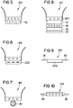
- FIG. 3 shows a protective profile SP2, which consists of a cable protective middle part MT and lateral edges R, the edges R are flexible so that the winding on a drain drum is possible.
- the edges are therefore for example also provided with slots S, so that the Flexibility of the entire winding arrangement improved becomes.
- Figure 4 shows a protective profile SP3 with embedded Longitudinal elements LE, which are used for reinforcement and suitable Training also serve as a current or transmission conductor.
- the width BMT of the middle part is 8 to 9 mm
- the thickness SMT of the middle part MT is approx. 3 mm
- the The length LR of the flexible edges R is 7 mm
- the thickness SR of a flexible edge R is 0.5 to 1 mm.
- the wide one open distance AR of the edges R is preferably 15 mm with a U-shaped cross section.
- Figure 5 shows a protection profile SP4, in which a oval fiber optic maxi bundle MB on its middle part is attached.
- Figure 6 shows a protective profile SP5 with a molded Optical fiber ribbon, this preferably so is molded that it is easily from the protective profile SP5 is separable.
- FIG. 7 shows a protective profile SP5 with one on the middle part attached fiber optic micro cable MK.
- Figure 8 shows a protection profile SP6, which consists of several Layers exists, with the middle part as SMT7 Protective layer is formed with inserted longitudinal elements.
- the layer S1 serves as a damping layer and consists of physically cellular polyurethane (PU) with spherical Trained cavities that prevent water from entering Avoid longitudinal direction.
- Layer S2 contains for example wires or optical fibers for Transmission purposes and layer S3 is again as Protective layer formed.
- Layer S4 is off Polyethylene (PE). It causes in when using glass fibers Layer S2 that the micro cable M6 or another itself material underneath is not pressed through.
- PE Polyethylene
- FIG. 9 shows a protective profile SP8 that is particularly easy to wind, where the flexible edges R8 in the form of lamellar, flexible tapes without gradation in one level from Stand out middle part SMT8.
- Figure 10 shows a protective profile SP9 with on both sides in the center of Middle part outgoing flexible edges R9, being here again a protective profile with longitudinal elements as an example is selected.
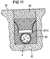
- FIG. 11 shows a fully fitted installation groove VN, which is shown in a road surface SO a laying reason VG has been introduced.
- this is the UV installed cables K can be seen, over which a protection profile SP10 is arranged, with its edges against the Walls of the installation channel VN spread.
- the remaining Cavities of the Verlenut VN are filled with a filler to Example filled up with bituminous sand BS.
- it can also additional fillers are introduced, which at Ingress of water show swelling effect and thus prevent further water ingress.
Landscapes
- Physics & Mathematics (AREA)
- General Physics & Mathematics (AREA)
- Optics & Photonics (AREA)
- Engineering & Computer Science (AREA)
- General Engineering & Computer Science (AREA)
- Architecture (AREA)
- Civil Engineering (AREA)
- Structural Engineering (AREA)
- Light Guides In General And Applications Therefor (AREA)
- Electric Cable Arrangement Between Relatively Moving Parts (AREA)
- Laying Of Electric Cables Or Lines Outside (AREA)
- Manufacturing Of Electrical Connectors (AREA)
Abstract
Description
- Das in die Verlegenut eingelegte Kabel wird fixiert, wobei der Restraum der Verlegenut vorzugsweise mit bituminösem Sand aufgefüllt wird.
- Das Kabel wird gegen mechanische Einwirkungen geschützt.
- Das Kabel wird beim Auffüllen der Verlegenut mit heißem Bitumen vor Wärmeeinwirkung geschützt.
- Im Reparaturfall läßt sich die Verlegenut durch Herausziehen des Schutzprofils leicht öffnen, ohne daß das Kabel beansprucht wird.
- Bei zusätzlichen Einlagen von Drähten in das Schutzprofil können entsprechende Übertragungen erfolgen.
- Figur 1
- zeigt die Einlegevorrichtung.
- Figur 2
- zeigt eine Verlegenut mit eingeführtem Kabel und darüber angeordnetem Schutzprofil.
- Figur 3
- zeigt ein Schutzprofil.
- Figur 4
- zeigt ein Schutzprofil mit eingelegten Längseinheiten.
- Figur 5
- zeigt ein Schutzprofil mit einem angehängten ovalen Maxibündel.
- Figur 6
- zeigt ein Schutzprofil mit angehängtem Lichtwellenleiterbündel.
- Figur 7
- zeigt ein Schutzprofil mit einem angehängten Mikrokabel.
- Figur 8
- zeigt ein mehrschichtiges Schutzprofil.
- Figur 9
- zeigt ein Schutzprofil mit abstehenden Rändern.
- Figur 10
- zeigt ein weiteres Schutzprofil mit abstehenden Rändern.
- Figur 11
- zeigt eine aufgefüllte Verlegenut.
Claims (24)
- Einlegevorrichtung zum Einlegen eines langgestreckten Schutzprofils oberhalb eines in einer Verlegenut verlegten Kabels,
dadurch gekennzeichnet,
daß eine Ablauftrommel (AT) mit dem langgestreckten Schutzprofil (SP) auf einer fahrbaren Einlegevorrichtung (EV) angeordnet ist, daß Führungsrollen (FR) zum Positionieren des in die Verlegenut (VN) einzulegenden Schutzprofils (SP) vor einer in die Verlegenut (VN) eingreifenden Eindrückrolle (ER) angeordnet sind und daß das Schutzprofil (SP) flexible, beim Einlegevorgang gegen die Wandungen der Verlegenut (VN) spreizbare Ränder (R) aufweist, wobei das Schutzprofil (SP) zunächst auf der Ablauftrommel (AT) aufgewickelt ist. - Einlegevorrichtung nach Anspruch 1,
dadurch gekennzeichnet,
daß eine Vorführung (VF) vor den Führungsrollen (FR) angeordnet ist. - Einlegevorrichtung nach einem der vorhergehenden Ansprüche,
dadurch gekennzeichnet,
daß die Ablauftrommel (AT) mit einer Bremse (TB) versehen ist. - Einlegevorrichtung nach einem der vorhergehenden Ansprüche,
dadurch gekennzeichnet,
daß die Ränder (R8) des auf der Ablauftrommel aufgewickelten Schutzprofils (SP8) durchgehend ohne Abstufung in einer Ebene verlaufen. - Einlegevorrichtung nach einem der Ansprüche 1 bis 3,
dadurch gekennzeichnet,
daß die Ränder (R) des auf der Ablauftrommel aufgewickelten Schutzprofils (SP2) mit querverlaufenden Schlitzen versehen sind. - Einlegevorrichtung nach einem der vorhergehenden Ansprüche,
dadurch gekennzeichnet,
daß die Ränder des auf der Ablauftrommel aufgewickelten Schutzprofils im aufgetrommelten Zustand jeweils flach abstehend geformt sind. - Einlegevorrichtung nach einem der vorhergehenden Ansprüche,
dadurch gekennzeichnet,
daß das auf der Ablauftrommel aufgewickelte Schutzprofil (SP3, SP4, SP5, SP6, SP7, SP9) im jeweiligen Mittelteil längsverlaufende Elemente (LE) aufweist, insbesondere elektrische Drähte oder Lichtwellenleiter. - Einlegevorrichtung nach einem der vorhergehenden Ansprüche,
dadurch gekennzeichnet,
daß das auf der Ablauftrommel aufgewickelte Schutzprofil (SP4, SP5) mit einem Lichtwellenleitermaxibündel (MB) oder einem Lichtwellenleiter-Bändchen (LWLB) versehen ist. - Einlegevorrichtung nach einem der Ansprüche 1 bis 7,
dadurch gekennzeichnet,
daß das auf der Ablauftrommel aufgewickelte Schutzprofil (SP6) eines Mikrokabels (MK), bestehend aus einem Rohr und darin eingebrachten Lichtwellenleitern angeordnet ist. - Einlegevorrichtung nach einem der vorhergehenden Ansprüche,
dadurch gekennzeichnet,
daß das auf der Ablauftrommel aufgewickelte Schutzprofil (SP7) aus mehreren Schichten besteht. - Einlegevorrichtung nach Anspruch 10,
dadurch gekennzeichnet,
daß eine Schicht oder mehrere Schichten Lichtwelenleiter enthalten. - Einlegevorrichtung nach Anspruch 10 oder 11,
dadurch gekennzeichnet,
daß eine Schicht (S1) als Dämpfungsschicht ausgebildet ist und vorzugsweise aus geschäumtem Kunststoffmaterial besteht. - Einlegevorrichtung nach einem der Ansprüche 10 bis 12,
dadurch gekennzeichnet,
daß mindestens eine Schicht quer- und längswasserdicht ist. - Einlegevorrichtung nach einem der vorhergehenden Ansprüche,
dadurch gekennzeichnet,
daß das auf der Ablauftrommel aufgewickelte Schutzprofil (SP3) im Mittelteil (MT) eine Stärke (SMT) von 1,5 bis 3 mm aufweist, daß die Ränder (R) eine Stärke (SR) von 0,5 bis 1 mm aufweisen, daß die flexiblen Ränder (R) eine Länge (LR) von 5 bis 10 mm aufweisen. - Einlegevorrichtung nach einem der vorhergehenden Ansprüche,
dadurch gekennzeichnet,
daß das auf der Ablauftrommel aufgewickelte Schutzprofil (SP3) für eine Verlegenut von 10 mm Breite ein Mittelteil (MT) mit einer Breite (BMT) von 8 bis 9 mm aufweist und daß der weite Abstand der Ränder (R) eine Abstandsbreite (AR) von 15 mm aufweist. - Einlegevorrichtung nach einem der vorhergehenden Ansprüche,
dadurch gekennzeichnet,
daß das auf der Ablauftrommel aufgewickelte Schutzprofil jeweils beim Einlegen U-förmig auffaltbar ist und daß die beiden aufgefalteten Ränder an den Enden schräg nach auswärts gestellt sind. - Einlegevorrichtung nach einem der vorhergehenden Ansprüche,
dadurch gekennzeichnet,
daß das auf der Ablauftrommel aufgewickelte Schutzprofil aus glasfaserverstärktem Poyester besteht. - Einlegevorrichtung nach einem der Ansprüche 1 bis 16,
dadurch gekennzeichnet,
daß das auf der Ablauftrommel aufgewickelte Schutzprofil aus Polvinylchlorid (PVC) besteht. - Einlegevorrichtung nach einem der Ansprüche 1 bis 16,
dadurch gekennzeichnet,
daß das auf der Ablauftrommel aufgewickelte Schutzprofil aus High-Density-Polyethylen (HDPE) besteht. - Einlegevorrichtung nach einem der vorhergehenden Ansprüche,
dadurch gekennzeichnet,
daß eine Vorrichtung zum Einbringen eines Quellmittels in Form von Quellfäden, eines Quellvlieses oder einer Quellfüllmasse vor dem Einlegen des Schutzprofils in der Verlegenut (VN) angeordnet ist. - Einlegevorrichtung nach einem der Ansprüche 1 bis 19,
dadurch gekennzeichnet,
daß eine Vorrichtung zum Einbringen einer flexiblen Füllmasse vor dem Einlegen des Schutzprofils in der Verlegenut (VN) angeordnet ist. - Einlegevorrichtung nach einem der vorhergehenden Ansprüche,
dadurch gekennzeichnet,
daß eine Ablauftrommel mit einem Mikrokabel (MK) angeordnet ist, das aus einem Rohr und darin eingebrachten Lichtwellenleitern besteht. - Einlegevorrichtung nach einem der vorhergehenden Ansprüche,
dadurch gekennzeichnet,
daß die Einlegevorrichtung selbstfahrbar ausgerüstet ist. - Einlegevorrichtung nach einem der vorhergehenden Ansprüche,
dadurch gekennzeichnet,
daß die Einlegevorrichtung auf einem Kabelverlegewagen integriert ist.
Applications Claiming Priority (2)
| Application Number | Priority Date | Filing Date | Title |
|---|---|---|---|
| DE19808945 | 1998-03-03 | ||
| DE19808945 | 1998-03-03 |
Publications (2)
| Publication Number | Publication Date |
|---|---|
| EP0940696A1 true EP0940696A1 (de) | 1999-09-08 |
| EP0940696B1 EP0940696B1 (de) | 2007-08-29 |
Family
ID=7859509
Family Applications (1)
| Application Number | Title | Priority Date | Filing Date |
|---|---|---|---|
| EP98121105A Expired - Lifetime EP0940696B1 (de) | 1998-03-03 | 1998-11-09 | Einlegungsvorrichtung zum Einlegen eines langgestreckten Schutzprofils oberhalb eines in einer Verlegenut verlegten Kabels |
Country Status (7)
| Country | Link |
|---|---|
| US (2) | US6236798B1 (de) |
| EP (1) | EP0940696B1 (de) |
| AR (1) | AR018298A1 (de) |
| AT (1) | ATE371877T1 (de) |
| AU (1) | AU1855199A (de) |
| BR (1) | BR9900830A (de) |
| DE (1) | DE59814086D1 (de) |
Cited By (3)
| Publication number | Priority date | Publication date | Assignee | Title |
|---|---|---|---|---|
| FR2821141A1 (fr) * | 2001-02-21 | 2002-08-23 | Louis Dreyfus Comm | Procede de pose d'une conduite dans le sol |
| DE10242939B3 (de) * | 2002-09-16 | 2004-07-29 | CCS Technology, Inc., Wilmington | Verfahren und Vorrichtung zum Einbringen einer Anordnung zur Aufnahme mindestens einer optischen Ader in einen weg- oder straßenartigen Verlegegrund, sowie Verlegeanordnung mit einer derartigen Anordnung |
| CN112103842A (zh) * | 2020-09-14 | 2020-12-18 | 国网山东省电力公司商河县供电公司 | 一种用于电缆沟的电缆敷设装置 |
Families Citing this family (9)
| Publication number | Priority date | Publication date | Assignee | Title |
|---|---|---|---|---|
| US8464302B1 (en) | 1999-08-03 | 2013-06-11 | Videoshare, Llc | Method and system for sharing video with advertisements over a network |
| US7302802B2 (en) * | 2003-10-14 | 2007-12-04 | Pratt & Whitney Canada Corp. | Aerodynamic trip for a combustion system |
| US8457464B2 (en) * | 2011-09-26 | 2013-06-04 | Hubbell Incorporated | Cable enclosure and radius-limiting cable guide with integral magnetic door catch |
| US9588315B1 (en) * | 2014-03-28 | 2017-03-07 | Daniel Ryan Turner | Method and apparatus for deployment of a communication line onto a surface such as a roadway or pathway |
| US10866380B2 (en) * | 2017-07-28 | 2020-12-15 | Traxyl, Inc. | Method and apparatus for deployment of a communication line onto a surface such as a roadway or pathway |
| CN110544904A (zh) * | 2019-08-20 | 2019-12-06 | 胡立泉 | 一种地下电缆送线装置 |
| US11572699B2 (en) * | 2020-02-03 | 2023-02-07 | Chris Paisley | Embedded concrete marking |
| EP4179374B1 (de) | 2020-07-07 | 2026-04-08 | Traxyl, Inc. | Verfahren und vorrichtung zum einsetzen eines rohrförmigen körpers auf eine oberfläche |
| WO2022264310A1 (ja) * | 2021-06-16 | 2022-12-22 | 日本電信電話株式会社 | 光ケーブル敷設方法 |
Citations (2)
| Publication number | Priority date | Publication date | Assignee | Title |
|---|---|---|---|---|
| US3570379A (en) * | 1969-06-26 | 1971-03-16 | Robert J Johnson | Sealant strip installing machine |
| WO1997020236A2 (de) * | 1995-11-13 | 1997-06-05 | Siemens Aktiengesellschaft | Verfahren zum einbringen eines optischen kabels in einen festen verlegegrund |
Family Cites Families (4)
| Publication number | Priority date | Publication date | Assignee | Title |
|---|---|---|---|---|
| FR2500638A1 (fr) * | 1981-02-20 | 1982-08-27 | Laurette Michel | Cable a fibres optiques |
| DE4041030A1 (de) * | 1990-12-20 | 1992-07-02 | Siemens Ag | Krimpspleiss |
| JP3022015U (ja) * | 1995-08-24 | 1996-03-12 | モレックス インコーポレーテッド | 光ファイバーケーブル用コネクタ |
| KR20000023391A (ko) * | 1998-09-25 | 2000-04-25 | 오카야마 노리오 | 광 케이블 및 그 제조 방법 |
-
1998
- 1998-11-09 DE DE59814086T patent/DE59814086D1/de not_active Expired - Fee Related
- 1998-11-09 AT AT98121105T patent/ATE371877T1/de not_active IP Right Cessation
- 1998-11-09 EP EP98121105A patent/EP0940696B1/de not_active Expired - Lifetime
-
1999
- 1999-03-01 AR ARP990100865A patent/AR018298A1/es active IP Right Grant
- 1999-03-02 US US09/260,906 patent/US6236798B1/en not_active Expired - Lifetime
- 1999-03-02 AU AU18551/99A patent/AU1855199A/en not_active Abandoned
- 1999-03-02 BR BR9900830-0A patent/BR9900830A/pt not_active Application Discontinuation
-
2001
- 2001-05-21 US US09/862,105 patent/US6546183B2/en not_active Expired - Lifetime
Patent Citations (2)
| Publication number | Priority date | Publication date | Assignee | Title |
|---|---|---|---|---|
| US3570379A (en) * | 1969-06-26 | 1971-03-16 | Robert J Johnson | Sealant strip installing machine |
| WO1997020236A2 (de) * | 1995-11-13 | 1997-06-05 | Siemens Aktiengesellschaft | Verfahren zum einbringen eines optischen kabels in einen festen verlegegrund |
Cited By (3)
| Publication number | Priority date | Publication date | Assignee | Title |
|---|---|---|---|---|
| FR2821141A1 (fr) * | 2001-02-21 | 2002-08-23 | Louis Dreyfus Comm | Procede de pose d'une conduite dans le sol |
| DE10242939B3 (de) * | 2002-09-16 | 2004-07-29 | CCS Technology, Inc., Wilmington | Verfahren und Vorrichtung zum Einbringen einer Anordnung zur Aufnahme mindestens einer optischen Ader in einen weg- oder straßenartigen Verlegegrund, sowie Verlegeanordnung mit einer derartigen Anordnung |
| CN112103842A (zh) * | 2020-09-14 | 2020-12-18 | 国网山东省电力公司商河县供电公司 | 一种用于电缆沟的电缆敷设装置 |
Also Published As
| Publication number | Publication date |
|---|---|
| US6546183B2 (en) | 2003-04-08 |
| AR018298A1 (es) | 2001-11-14 |
| US6236798B1 (en) | 2001-05-22 |
| EP0940696B1 (de) | 2007-08-29 |
| DE59814086D1 (de) | 2007-10-11 |
| BR9900830A (pt) | 1999-12-14 |
| ATE371877T1 (de) | 2007-09-15 |
| AU1855199A (en) | 1999-09-16 |
| US20010022881A1 (en) | 2001-09-20 |
Similar Documents
| Publication | Publication Date | Title |
|---|---|---|
| DE4205574C2 (de) | Kanalkörper und Verfahren zum Verlegen eines Kabels in diesem | |
| DE60029848T2 (de) | Verfahren und Vorrichtung zum Unterteilen eines Kanals in Kammern | |
| EP1628790B1 (de) | Schutznetz, insbesondere für einen steinschlagschutz oder für eine böschungssicherung | |
| DE69704796T2 (de) | Kabelnetz | |
| DE2840966C2 (de) | Sicherungseinrichtung | |
| DE69022188T2 (de) | Herstellungsverfahren eines elektrischen Freileitungskabels zum Energietransport und Einrichtung zur Durchführung dieses Verfahrens. | |
| EP0940696A1 (de) | Einlegungsvorrichtung zum Einlegen eines langgestreckten Schutzprofils oberhalb eines in einer Verlegenut verlegten Kabels | |
| DE3217401C2 (de) | Kabelführungsaggregat aus Kunststoff mit einer Mehrzahl von Kabelführungsrohen | |
| DE3624124A1 (de) | Nachrichtenkabel mit lichtwellenleitern | |
| DE3208172C2 (de) | ||
| DE19724685C1 (de) | Verfahren zur Herstellung eines flexiblen Leitungsstranges | |
| DE2201195A1 (de) | Stroemungsguenstig verkleidetes schleppkabel | |
| DE2715394A1 (de) | Halterung fuer heizungsrohre | |
| DE2723359C3 (de) | Kabelschutz | |
| DE29821884U1 (de) | Befestigungsvorrichtung | |
| DE8213407U1 (de) | Kabelführungsaggregat | |
| DE19816015B4 (de) | Verfahren zum Installieren eines Kabels oder Kabelstranges in ein Fahrzeugteil | |
| DE102021120939A1 (de) | Elektrisches Flächentemperiersystem und Verlegevorrichtung für Heizkabel des elektrischen Flächentemperiersystems | |
| DE3234730A1 (de) | Nachrichtenkabel | |
| DE202019106612U1 (de) | Vorrichtung zum Reduzieren eingebetteter oder eigener Reibung in einem Mehrleitungsrohr | |
| DE2416578A1 (de) | Vorrichtung zur vorfertigung einer einbau-waermeaustauschstruktur. | |
| DE10003695A1 (de) | Verfahren sowie Kunststoffrohr und LWL-Element und Befestigungseinrichtung zum Bestücken von Freileitungsanlagen mit LWL-Übertragungsleitungen | |
| DE69106357T2 (de) | Verfahren zur Herstellung einer Verseileinheit mit abschnittsweise wechselnder Drallrichtung. | |
| DE102021128334B4 (de) | Kabelverbund | |
| DE3718275A1 (de) | Kunststoffrohr |
Legal Events
| Date | Code | Title | Description |
|---|---|---|---|
| PUAI | Public reference made under article 153(3) epc to a published international application that has entered the european phase |
Free format text: ORIGINAL CODE: 0009012 |
|
| AK | Designated contracting states |
Kind code of ref document: A1 Designated state(s): AT CH DE ES FR GB IT LI |
|
| AX | Request for extension of the european patent |
Free format text: AL;LT;LV;MK;RO;SI |
|
| 17P | Request for examination filed |
Effective date: 19991005 |
|
| AKX | Designation fees paid |
Free format text: AT CH DE ES FR GB IT LI |
|
| RAP1 | Party data changed (applicant data changed or rights of an application transferred) |
Owner name: CCS TECHNOLOGY, INC. |
|
| 17Q | First examination report despatched |
Effective date: 20041012 |
|
| GRAP | Despatch of communication of intention to grant a patent |
Free format text: ORIGINAL CODE: EPIDOSNIGR1 |
|
| GRAS | Grant fee paid |
Free format text: ORIGINAL CODE: EPIDOSNIGR3 |
|
| GRAA | (expected) grant |
Free format text: ORIGINAL CODE: 0009210 |
|
| AK | Designated contracting states |
Kind code of ref document: B1 Designated state(s): AT CH DE ES FR GB IT LI |
|
| REG | Reference to a national code |
Ref country code: GB Ref legal event code: FG4D Free format text: NOT ENGLISH |
|
| REG | Reference to a national code |
Ref country code: CH Ref legal event code: EP |
|
| REF | Corresponds to: |
Ref document number: 59814086 Country of ref document: DE Date of ref document: 20071011 Kind code of ref document: P |
|
| GBT | Gb: translation of ep patent filed (gb section 77(6)(a)/1977) |
Effective date: 20071031 |
|
| ET | Fr: translation filed | ||
| PG25 | Lapsed in a contracting state [announced via postgrant information from national office to epo] |
Ref country code: ES Free format text: LAPSE BECAUSE OF FAILURE TO SUBMIT A TRANSLATION OF THE DESCRIPTION OR TO PAY THE FEE WITHIN THE PRESCRIBED TIME-LIMIT Effective date: 20071210 |
|
| PGFP | Annual fee paid to national office [announced via postgrant information from national office to epo] |
Ref country code: GB Payment date: 20071128 Year of fee payment: 10 Ref country code: FR Payment date: 20071119 Year of fee payment: 10 |
|
| PGFP | Annual fee paid to national office [announced via postgrant information from national office to epo] |
Ref country code: DE Payment date: 20071221 Year of fee payment: 10 |
|
| PLBE | No opposition filed within time limit |
Free format text: ORIGINAL CODE: 0009261 |
|
| STAA | Information on the status of an ep patent application or granted ep patent |
Free format text: STATUS: NO OPPOSITION FILED WITHIN TIME LIMIT |
|
| PG25 | Lapsed in a contracting state [announced via postgrant information from national office to epo] |
Ref country code: LI Free format text: LAPSE BECAUSE OF NON-PAYMENT OF DUE FEES Effective date: 20071130 Ref country code: CH Free format text: LAPSE BECAUSE OF NON-PAYMENT OF DUE FEES Effective date: 20071130 |
|
| REG | Reference to a national code |
Ref country code: CH Ref legal event code: PL |
|
| 26N | No opposition filed |
Effective date: 20080530 |
|
| PG25 | Lapsed in a contracting state [announced via postgrant information from national office to epo] |
Ref country code: AT Free format text: LAPSE BECAUSE OF NON-PAYMENT OF DUE FEES Effective date: 20071109 |
|
| GBPC | Gb: european patent ceased through non-payment of renewal fee |
Effective date: 20081109 |
|
| REG | Reference to a national code |
Ref country code: FR Ref legal event code: ST Effective date: 20090731 |
|
| PG25 | Lapsed in a contracting state [announced via postgrant information from national office to epo] |
Ref country code: DE Free format text: LAPSE BECAUSE OF NON-PAYMENT OF DUE FEES Effective date: 20090603 |
|
| PG25 | Lapsed in a contracting state [announced via postgrant information from national office to epo] |
Ref country code: GB Free format text: LAPSE BECAUSE OF NON-PAYMENT OF DUE FEES Effective date: 20081109 |
|
| PG25 | Lapsed in a contracting state [announced via postgrant information from national office to epo] |
Ref country code: IT Free format text: LAPSE BECAUSE OF NON-PAYMENT OF DUE FEES Effective date: 20071130 |
|
| PG25 | Lapsed in a contracting state [announced via postgrant information from national office to epo] |
Ref country code: FR Free format text: LAPSE BECAUSE OF NON-PAYMENT OF DUE FEES Effective date: 20081130 |