EP0940766A2 - Einrichtung und Verfahren zur Kartenreinigung - Google Patents
Einrichtung und Verfahren zur Kartenreinigung Download PDFInfo
- Publication number
- EP0940766A2 EP0940766A2 EP99301502A EP99301502A EP0940766A2 EP 0940766 A2 EP0940766 A2 EP 0940766A2 EP 99301502 A EP99301502 A EP 99301502A EP 99301502 A EP99301502 A EP 99301502A EP 0940766 A2 EP0940766 A2 EP 0940766A2
- Authority
- EP
- European Patent Office
- Prior art keywords
- card
- cleaning
- cleaning roller
- length
- roller
- Prior art date
- Legal status (The legal status is an assumption and is not a legal conclusion. Google has not performed a legal analysis and makes no representation as to the accuracy of the status listed.)
- Withdrawn
Links
Images


Classifications
-
- G—PHYSICS
- G06—COMPUTING OR CALCULATING; COUNTING
- G06K—GRAPHICAL DATA READING; PRESENTATION OF DATA; RECORD CARRIERS; HANDLING RECORD CARRIERS
- G06K13/00—Conveying record carriers from one station to another, e.g. from stack to punching mechanism
- G06K13/02—Conveying record carriers from one station to another, e.g. from stack to punching mechanism the record carrier having longitudinal dimension comparable with transverse dimension, e.g. punched card
- G06K13/08—Feeding or discharging cards
- G06K13/0868—Feeding or discharging cards using an arrangement for keeping the feeding or insertion slot of the card station clean of dirt, or to avoid feeding of foreign or unwanted objects into the slot
- G06K13/0893—Feeding or discharging cards using an arrangement for keeping the feeding or insertion slot of the card station clean of dirt, or to avoid feeding of foreign or unwanted objects into the slot the arrangement comprising means for cleaning the card upon insertion
-
- G—PHYSICS
- G06—COMPUTING OR CALCULATING; COUNTING
- G06K—GRAPHICAL DATA READING; PRESENTATION OF DATA; RECORD CARRIERS; HANDLING RECORD CARRIERS
- G06K7/00—Methods or arrangements for sensing record carriers, e.g. for reading patterns
- G06K7/0013—Methods or arrangements for sensing record carriers, e.g. for reading patterns by galvanic contacts, e.g. card connectors for ISO-7816 compliant smart cards or memory cards, e.g. SD card readers
- G06K7/0021—Methods or arrangements for sensing record carriers, e.g. for reading patterns by galvanic contacts, e.g. card connectors for ISO-7816 compliant smart cards or memory cards, e.g. SD card readers for reading/sensing record carriers having surface contacts
Definitions
- This invention relates to an apparatus and method for cleaning a surface of an optical or a magnetical information recording card used for recording and/or reproducing information.
- An optical card information recording and/or reproducing apparatus usually has built-in a cleaning system for cleaning dirt on the card surface because of the bad influence of dirt adhered to a card surface on recording and/or reproducing.
- Figure 1 shows a sectional view of a conventional optical card information recording and/or reproducing apparatus.
- a pair of cleaning rollers 2 and a pair of conveyor rollers 3 are provided in the information recording and/or reproducing apparatus 1.
- the cleaning roller 2 stops rotating and the conveyor roller 3 rotates in the direction of insertion of the card C.
- the cleaning roller 2 and the conveyor roller 3 rotate in the direction of discharge of the card C.
- FIGs 2-4 illustrate the processes of insertion and discharge of the card C.
- the card C is conveyed until the card C is between the cleaning roller 2 and conveyor roller 3.
- the card C is then cleaned by the cleaning roller 2, the dirt D being gathered by the cleaning roller 2.
- the cleaning roller 2 and conveyor roller 3 rotate in the discharging direction. As shown in Figures 3 and 4, the card C is then discharged from the apparatus 1.
- the dirt D which is gathered by the cleaning roller 2, as shown in Figure 4, adheres on the cleaning roller 2 and is left in the apparatus 1 after the card C is discharged.
- the dirt D adhered to the cleaning roller 2 disperses inside the apparatus and it is possible that the dispersed dirt D exerts a bad influence upon recording and/or reproducing operations.
- the dirt D is left on the cleaning roller 2, there is the problem that the dirt D adhering to the cleaning roller 2 is difficult to remove.
- the dirt D which is gathered at each cleaning operation,may pile up and the cleaning performance declines and reduces the lifetime of the cleaning parts.
- an object of this invention to at least alleviate the above problems.
- an object is to supply a cleaning apparatus which may automatically carry out cleaning of the card without reducing the cleaning performance, and which may improve the lifetime of the cleaning parts.
- a cleaning apparatus or method in which the length of the circumference of the surface of the cleaning roller and the pressure of the cleaning roller to the surface of the card are controlled.
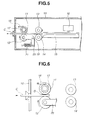
- the cleaning roller 11 is arranged near the opening for inserting the card C, a conveyor roller 12 being arranged so as to oppose the cleaning roller 11. Further conveyor rollers 13 and 14 are arranged opposing each other at the back of the cleaning roller 11 and the first conveyor roller 12.
- a tray 15 for carrying the card C is arranged at the back of the conveyor rollers 13 and 14, with the optical head 16 being arranged above the tray 15.
- a ratchet gear 17 is fixed on the axis of rotation of the cleaning roller 11, with a ratchet nail 18 being arranged to stop the rotation of the cleaning roller 11 by biting onto the ratchet gear 17.
- the end of an L-shaped conveyor lever 20 which is rotationally supported by a lever pin 19, is fixed on the axis of rotation of the conveyor roller 12.
- the other end of the conveyor lever 20 is connected with a spring 21 which biases the position of the conveyor roller 12 towards the cleaning roller 11.
- the pressure of the cleaning roller 11 on the surface of the card is set by adjusting the power of the spring 21, the effect of the pressure being described in more detail later.
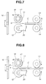
- Figure 6 and Figure 7 shows the insertion operation of the card C.
- the card C when the card C is inserted in the opening in the optical card information recording and/or reproducing apparatus, the card C passes between the cleaning roller 11 and the conveyor roller 12. The ratchet gear is then stopped by the ratchet nail 18 and the rotation of the cleaning roller 11 stops.
- the conveyor roller 12 rotates in the same direction as the insertion direction of the card C and conveys the card C towards the back of the apparatus 10.
- the card C is discharged from the apparatus 10.
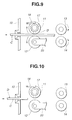
- FIG 8 and Figure 9 show the discharging operation of the card C.
- the card C is removed from the tray 15 and conveyed toward the cleaning roller 11 by the conveyor roller 13 and 14 rotating in the discharging direction.
- the ratchet nail 18 will dislocate from the ratchet gear 17 and the rotation of the cleaning roller 11 becomes free.
- the card C is conveyed towards the opening in the apparatus 10 by the rotation of the conveyor roller 12 in the discharging direction of the card C, while the card C is pressed under a predetermined pressure between the cleaning roller 11 and the conveyor roller 12.
- the length of the circumference of the cleaning surface of the cleaning roller 11 is set at not more than the length of the card C in the discharging direction.
- the frequency at which the dirt D gathered on the cleaning roller 11 is transferred to the surface of the card C, when the length of the circumference of the cleaning roller 11 is equal to the length of the card C, is once.
- it is one-half times as long as the length of the card C it is twice.
- Table 1 shows experimental data showing the degree of dirt D transfer to the surface of the card C from the cleaning roller 11 when the card C is discharged.
- the horizontal axis shows the pressure which acts on the surface of the card C between the cleaning roller 11 and conveyor roller 12 in units of Newtons.
- the vertical axis shows the length of the circumference of the cleaning surface of the cleaning roller 11 as a multiple of the length of the card C.
- the dirt D transferred from the cleaning roller 11 to the surface of the card C is more than 50%.
- the dirt D transferred from the cleaning roller 11 to the surface of the card C is less than 50%.
- the pressure on the surface of the card C is more than 1N and the length of the circumference of the cleaning roller 11 is not more than one-half the length of the card C.
- Table 2 shows the length of the circumference of the cleaning roller 11 as the horizontal axis and the lifetime of the card as the vertical axis. Table 2 also shows experimental data showing the cleaning performance as a function of the relationship between the length of the circumference of the cleaning roller 11 and the lifetime.
- the lifetime is the number of times a card C having the dirt on its surface is cleaned by the cleaning roller 11 in the apparatus 10 has acceptable recording/reproducing characteristics.
- the card C is inserted in the apparatus such that the dirt D is cleaned by the cleaning roller 11 a predetermined number of times. If it is then possible to record and/or reproduce from the card more than 99%, this is shown by ⁇ . If it is impossible to record and/or reproduce more than 99%, this is shown by X. NUMBER OF CARD PASSES 1,000 10,000 THE LENGTH OF THE CIRCUMFERENCE the length of the card C*1 ⁇ ⁇ the length of the card C*1/2 ⁇ ⁇ the length of the card C*1/4 ⁇ ⁇ the length of the card C*1/6 ⁇ ⁇ the length of the card C*1/7 ⁇ X the length of the card C*1/8 X X
- the length of the circumference of the cleaning roller 11 is set one-sixth time the length of the card C.
- Table 3 shows experimental data showing the relationships between the conveyance time of card C in the apparatus 10 and the pressure on the surface of the card C.
- the conveyance time of the card C is measured from the time at which the card C is inserted into the opening to the time at which the card C is positioned on the tray 15. When this time is within 1 second, this is indicated by ⁇ ; when this time exceeds the 1 second, this is indicated by X.
- PRESSURE (N) 0.4 0.6 0.8 1 2 3 4 5 6 7 CONVEYANCE TIME X X ⁇ ⁇ ⁇ ⁇ ⁇ ⁇ X X
- the conveyance time is longer because of slippage between the conveyor roller 12 and the card C.
- the permissible range of the conveyor time of the card C is within 1 second, it is expedient that the pressure is between about 1 to 5N.
- a recording and/or reproducing apparatus an apparatus that performs at least one of the functions of recording information on, and reproducing information from a recording medium.
Landscapes
- Engineering & Computer Science (AREA)
- Physics & Mathematics (AREA)
- General Physics & Mathematics (AREA)
- Theoretical Computer Science (AREA)
- Artificial Intelligence (AREA)
- Computer Vision & Pattern Recognition (AREA)
- Conveying Record Carriers (AREA)
Applications Claiming Priority (2)
| Application Number | Priority Date | Filing Date | Title |
|---|---|---|---|
| JP10073556A JPH11260035A (ja) | 1998-03-06 | 1998-03-06 | クリーニング装置 |
| JP7355698 | 1998-03-06 |
Publications (2)
| Publication Number | Publication Date |
|---|---|
| EP0940766A2 true EP0940766A2 (de) | 1999-09-08 |
| EP0940766A3 EP0940766A3 (de) | 2000-12-20 |
Family
ID=13521652
Family Applications (1)
| Application Number | Title | Priority Date | Filing Date |
|---|---|---|---|
| EP99301502A Withdrawn EP0940766A3 (de) | 1998-03-06 | 1999-03-01 | Einrichtung und Verfahren zur Kartenreinigung |
Country Status (2)
| Country | Link |
|---|---|
| EP (1) | EP0940766A3 (de) |
| JP (1) | JPH11260035A (de) |
Cited By (1)
| Publication number | Priority date | Publication date | Assignee | Title |
|---|---|---|---|---|
| CN119670784A (zh) * | 2025-02-20 | 2025-03-21 | 广东首云信息技术有限公司 | 一种社保金融卡即时补换卡的即时发卡设备 |
Families Citing this family (1)
| Publication number | Priority date | Publication date | Assignee | Title |
|---|---|---|---|---|
| KR100961890B1 (ko) | 2008-05-13 | 2010-06-09 | 조명희 | 물걸레 청소기 |
Family Cites Families (4)
| Publication number | Priority date | Publication date | Assignee | Title |
|---|---|---|---|---|
| JPS50157914U (de) * | 1974-06-14 | 1975-12-27 | ||
| US4947029A (en) * | 1985-11-01 | 1990-08-07 | Canon Kabushiki Kaisha | Cleaning device for information recording medium |
| JPH0617253Y2 (ja) * | 1985-12-05 | 1994-05-02 | 株式会社日本コンラックス | 光学メモリ−カ−ドの読取り装置 |
| CA1321861C (en) * | 1987-08-11 | 1993-09-07 | Hideo Kurihara | Apparatus having mechanism for cleaning information record medium |
-
1998
- 1998-03-06 JP JP10073556A patent/JPH11260035A/ja active Pending
-
1999
- 1999-03-01 EP EP99301502A patent/EP0940766A3/de not_active Withdrawn
Cited By (1)
| Publication number | Priority date | Publication date | Assignee | Title |
|---|---|---|---|---|
| CN119670784A (zh) * | 2025-02-20 | 2025-03-21 | 广东首云信息技术有限公司 | 一种社保金融卡即时补换卡的即时发卡设备 |
Also Published As
| Publication number | Publication date |
|---|---|
| EP0940766A3 (de) | 2000-12-20 |
| JPH11260035A (ja) | 1999-09-24 |
Similar Documents
| Publication | Publication Date | Title |
|---|---|---|
| EP1280152A3 (de) | Informationsaufzeichnungsverfahren und Vorrichtung mit Zusatzaufzeichnungsfunktion | |
| EP1010537A3 (de) | Bandantrieb für einen auf Anfrage gesteuerten Drucker | |
| EP1441345A3 (de) | Aufzeichnungs- und Wiedergabegerät für optische Platte zur Durchführung eines Formatierungsverfahrens als Hintergrundverfahren und Methode zur Formatierung einer optischen Platte durch Hintergrundverfahren | |
| JP3145146B2 (ja) | 記録装置 | |
| EP0940766A2 (de) | Einrichtung und Verfahren zur Kartenreinigung | |
| DE3006063A1 (de) | Vorlagen-abnahmevorrichtung fuer eine automatische vorlagen-transporteinheit | |
| JP2002154713A (ja) | シート媒体を端と端とをつないで送る方法および装置 | |
| US5167409A (en) | Apparatus and method for aligning a sheet against a side registrating member using plural alignment devices | |
| EP0460606B1 (de) | Lese-/Schreibvorrichtung für eine Karte | |
| EP0884258A3 (de) | Schräglaufkorrektionsmechanismus in Druckern | |
| JP2819226B2 (ja) | カード搬送装置 | |
| US6344947B1 (en) | Head cleaner | |
| EP1206136A3 (de) | Vorrichtung und Verfahren zur Videodatenaufzeichnung | |
| JP3225341B2 (ja) | リードフレームのプッシャ装置 | |
| DE4438304A1 (de) | Druckverfahren und Drucker | |
| JPH07302308A (ja) | 光カード搬送装置 | |
| JP3005457B2 (ja) | 媒体搬送装置 | |
| JP2003271033A (ja) | クリーニング装置及び該クリーニング装置を有する画像形成装置 | |
| JPH096926A (ja) | 磁気カードリーダライタ | |
| JP2731934B2 (ja) | 情報記録媒体のクリーニング機構 | |
| JPH11167608A (ja) | 情報記録再生装置 | |
| JP3465821B2 (ja) | 記録カード洗浄装置 | |
| JPH0365363A (ja) | 記録媒体排出装置 | |
| JP3970343B2 (ja) | カードリーダ・ライタ | |
| JPH08129598A (ja) | 通帳類取扱装置 |
Legal Events
| Date | Code | Title | Description |
|---|---|---|---|
| PUAI | Public reference made under article 153(3) epc to a published international application that has entered the european phase |
Free format text: ORIGINAL CODE: 0009012 |
|
| AK | Designated contracting states |
Kind code of ref document: A2 Designated state(s): DE FR GB IT NL |
|
| AX | Request for extension of the european patent |
Free format text: AL;LT;LV;MK;RO;SI |
|
| PUAL | Search report despatched |
Free format text: ORIGINAL CODE: 0009013 |
|
| AK | Designated contracting states |
Kind code of ref document: A3 Designated state(s): AT BE CH CY DE DK ES FI FR GB GR IE IT LI LU MC NL PT SE |
|
| AX | Request for extension of the european patent |
Free format text: AL;LT;LV;MK;RO;SI |
|
| AKX | Designation fees paid |
Free format text: DE FR GB IT NL |
|
| STAA | Information on the status of an ep patent application or granted ep patent |
Free format text: STATUS: THE APPLICATION IS DEEMED TO BE WITHDRAWN |
|
| 18D | Application deemed to be withdrawn |
Effective date: 20010621 |