EP0940858A2 - Système photovoltaique de génération d'énergie - Google Patents
Système photovoltaique de génération d'énergie Download PDFInfo
- Publication number
- EP0940858A2 EP0940858A2 EP99104195A EP99104195A EP0940858A2 EP 0940858 A2 EP0940858 A2 EP 0940858A2 EP 99104195 A EP99104195 A EP 99104195A EP 99104195 A EP99104195 A EP 99104195A EP 0940858 A2 EP0940858 A2 EP 0940858A2
- Authority
- EP
- European Patent Office
- Prior art keywords
- solar cell
- current
- power source
- string
- output
- Prior art date
- Legal status (The legal status is an assumption and is not a legal conclusion. Google has not performed a legal analysis and makes no representation as to the accuracy of the status listed.)
- Withdrawn
Links
Images




Classifications
-
- H—ELECTRICITY
- H02—GENERATION; CONVERSION OR DISTRIBUTION OF ELECTRIC POWER
- H02S—GENERATION OF ELECTRIC POWER BY CONVERSION OF INFRARED RADIATION, VISIBLE LIGHT OR ULTRAVIOLET LIGHT, e.g. USING PHOTOVOLTAIC [PV] MODULES
- H02S40/00—Components or accessories in combination with PV modules, not provided for in groups H02S10/00 - H02S30/00
- H02S40/10—Cleaning arrangements
- H02S40/12—Means for removing snow
-
- H—ELECTRICITY
- H10—SEMICONDUCTOR DEVICES; ELECTRIC SOLID-STATE DEVICES NOT OTHERWISE PROVIDED FOR
- H10F—INORGANIC SEMICONDUCTOR DEVICES SENSITIVE TO INFRARED RADIATION, LIGHT, ELECTROMAGNETIC RADIATION OF SHORTER WAVELENGTH OR CORPUSCULAR RADIATION
- H10F77/00—Constructional details of devices covered by this subclass
- H10F77/95—Circuit arrangements
- H10F77/953—Circuit arrangements for devices having potential barriers
- H10F77/955—Circuit arrangements for devices having potential barriers for photovoltaic devices
-
- Y—GENERAL TAGGING OF NEW TECHNOLOGICAL DEVELOPMENTS; GENERAL TAGGING OF CROSS-SECTIONAL TECHNOLOGIES SPANNING OVER SEVERAL SECTIONS OF THE IPC; TECHNICAL SUBJECTS COVERED BY FORMER USPC CROSS-REFERENCE ART COLLECTIONS [XRACs] AND DIGESTS
- Y02—TECHNOLOGIES OR APPLICATIONS FOR MITIGATION OR ADAPTATION AGAINST CLIMATE CHANGE
- Y02E—REDUCTION OF GREENHOUSE GAS [GHG] EMISSIONS, RELATED TO ENERGY GENERATION, TRANSMISSION OR DISTRIBUTION
- Y02E10/00—Energy generation through renewable energy sources
- Y02E10/50—Photovoltaic [PV] energy
-
- Y—GENERAL TAGGING OF NEW TECHNOLOGICAL DEVELOPMENTS; GENERAL TAGGING OF CROSS-SECTIONAL TECHNOLOGIES SPANNING OVER SEVERAL SECTIONS OF THE IPC; TECHNICAL SUBJECTS COVERED BY FORMER USPC CROSS-REFERENCE ART COLLECTIONS [XRACs] AND DIGESTS
- Y10—TECHNICAL SUBJECTS COVERED BY FORMER USPC
- Y10S—TECHNICAL SUBJECTS COVERED BY FORMER USPC CROSS-REFERENCE ART COLLECTIONS [XRACs] AND DIGESTS
- Y10S136/00—Batteries: thermoelectric and photoelectric
- Y10S136/291—Applications
-
- Y—GENERAL TAGGING OF NEW TECHNOLOGICAL DEVELOPMENTS; GENERAL TAGGING OF CROSS-SECTIONAL TECHNOLOGIES SPANNING OVER SEVERAL SECTIONS OF THE IPC; TECHNICAL SUBJECTS COVERED BY FORMER USPC CROSS-REFERENCE ART COLLECTIONS [XRACs] AND DIGESTS
- Y10—TECHNICAL SUBJECTS COVERED BY FORMER USPC
- Y10S—TECHNICAL SUBJECTS COVERED BY FORMER USPC CROSS-REFERENCE ART COLLECTIONS [XRACs] AND DIGESTS
- Y10S136/00—Batteries: thermoelectric and photoelectric
- Y10S136/291—Applications
- Y10S136/293—Circuits
-
- Y—GENERAL TAGGING OF NEW TECHNOLOGICAL DEVELOPMENTS; GENERAL TAGGING OF CROSS-SECTIONAL TECHNOLOGIES SPANNING OVER SEVERAL SECTIONS OF THE IPC; TECHNICAL SUBJECTS COVERED BY FORMER USPC CROSS-REFERENCE ART COLLECTIONS [XRACs] AND DIGESTS
- Y10—TECHNICAL SUBJECTS COVERED BY FORMER USPC
- Y10S—TECHNICAL SUBJECTS COVERED BY FORMER USPC CROSS-REFERENCE ART COLLECTIONS [XRACs] AND DIGESTS
- Y10S323/00—Electricity: power supply or regulation systems
- Y10S323/906—Solar cell systems
Definitions
- the present invention relates to a photovoltaic power generating system, more specifically to a photovoltaic power generating system with the snow-melting function.
- a snow-melting system which supplies electric power to a solar cell or an exothermic body for heating with the aid of an external power source.
- a snow-melting system which uses a bidirectional inverter to supply electric power to a solar cell for heating with a switch provided for the bypass of a reverse-current preventive diode.
- the cell-heating scheme is simply capable of snow removal without need for the wiring for a heater and further becomes easy to install if the bidirectional operativity afforded, so that it is promising as a snow removal method for the photovoltaic power generating system.
- a photovoltaic power generating system with a solar cell array comprises of a plurality of strings connected in parallel which string is comprised of a plurality of solar cell modules connected in series, capable of making the solar cell array generate heat with the aid of an external power source, comprising: a current ON/OFF means individually switchable provided for each string; and a control unit for individually controlling the ON/OFF of the current switching means, wherein a current is applied to each string in sequence such that heat is generated.
- the current to be applied to each string may be either reverse or equal in direction to that of the generating time (the applied voltage may be either equal or reverse in direction to the generated voltage).
- overcurrent detecting means are and alarming means provided in the above external DC power source, so as to stop the application of current and issue an alarm on the occurrence time of overcurrent.
- the present invention has a switch for each string and energizes only the target string for snow-melting by the ON/OFF control thereof. Accordingly, in a system according to the present invention, the whole array is not energized all at once. Thus, only a small source capacity is required for the external DC power source and further the provision of alarming means enables the presence of a wrong string to be alarmed individually if any string wrong in behavior is present. Besides, since strings are individually energized, energization can be executed to the exclusion of the wrong strings, thus enabling the snow-melting running though partial.
- FIG. 1 A system according to this embodiment is shown in FIG. 1.
- the outputs of the above solar cell strings 1a and 1b are connected through the string switches 5a and 5b, reverse-current blocking diodes 2a and 2b and a load switch 6 to a resistance load 3 (5 ⁇ , 400 W grade).
- a voltage variable DC power source (maximum output: 50 V 5 A) with a commercial AC (unshown) employed for power source was prepared and its output is connected to through the string switches 5a and 5b to the solar cell strings 1a and 1b, respectively.
- the positive and negative terminals of the external power source 4 are connected to the anodes and cathodes of the solar cell strings 1a and 1b, respectively. If capable of supplying power to solar cell strings, any will do for the external power source 4 and a combination of an accumulator and a DC/DC converter or a dynamo may be employed.
- the voltage varying function is not especially essential. This is because specifying the configuration of a solar cell allows an appropriate applied voltage to be determined in advance.
- the string switches 5a and 5b are required only to withstand the output voltages and currents of the solar cell strings 5a and 5b for a system without heating function (e. g., snow-melting one), but required to withstand the voltage and current during the operation of the-heating (snow-melting) mode (in many cases, greater than the operating voltage and current of solar cell strings) in a system according to the present invention. Furthermore, they are preferably ON/OFF controllable in response to an electric signal.
- the control unit 7 is composed of a personal computer and a parallel IO interface (the electric circuit of a PC and those to be controlled are insulated from each other by means of a photocoupler). If a sequential control is permitted, a great variety of arrangements other than this can be assumed for the control unit 7 and an arrangement comprising a single chip microcomputer is handy and inexpensive in practical use.
- FIG. 2 One example of operation flow for the device of FIG. 1 is shown in FIG. 2.
- this device operates ordinarily in the power generation mode.
- This state is a state in which power supply is performed from the solar cell strings 1a and 1b to the load 3, where the string switches 5a and 5b are both in the state of ON, the load switch 6 is also in that of ON and the external power source switch 8 is in that of OFF.
- the external power source 4 is set to the state of being at rest. This state continues till the system enters the heating (snow-melting) mode.
- the heating (snow-melting) mode will be described.
- the heating (snow-melting) mode is executed at night.
- the running in the heating (snow-melting) mode is not impossible, but any consideration becomes necessary of the power generating operation of a solar cell. Namely, for a period of snows, since a solar cell generates no power, the same handling is possible as that of night-time, but when snow come gradually off and light begins to be incident on the solar cell, the solar cell begins to partially generate power and consequently a contrivance for promoting the supply voltage from the external power source or the like becomes necessary.
- the load switch 6 In the heating (snow-melting) mode, the load switch 6 is first turned OFF, thereby breaking the connection to a load 3.
- one string switch (here, 5b) is turned OFF by a string ON/OFF command signal from the control unit 7 so as to allow a current to flow only through a single string.
- the external power source 4 is set in motion and the external power switch 8 is turned ON to apply a current to solar cells for heating. Here, they are heated for 30 min. It is confirmed that the current and voltage of this time are 46 V and about 140 W and that the temperature rose by about 10°C for 30 min.
- the string switch 5a in the state of ON is turned OFF and another string switch (here, 5b) is turned ON, thereby heating another string as with the above string to carry out a snow-melting operation.
- the external power source switch 8 is turned OFF to stop the supply from the external power source 4, the string switch 5a and load switch 6 are turned ON (5b remains ON) to return the system to the initial state and the running is terminated.
- the capacity of the external power source prepared in this embodiment is 50 V 5 A, but it is evident that an external power source greater in capacity becomes necessary for simultaneous heating of both strings, thus resulting in device cost up. It is also obviously understood that the cost difference increases with increasing number of strings.
- this embodiment is applicable to an optional device to a normal photovoltaic power generating system as well.
- an ordinary commercial power source or accumulator may be used.
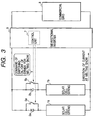
- FIG. 3 shows the configuration of this embodiment.
- Solar cell strings 1a and 1b are constructed as a 10 series and 2 parallel connection of amorphous solar cell modules with a photoelectric converter layer comprising three layers made of amorphous silicon.
- the solar cell employed in this embodiment has a relatively low efficiency of power generation per area and accordingly the covering ratio of the roof can be made greater than obtained in a system using a crystal type solar cell of the same capacity.
- This is suitable for the purpose of "snow-melting".
- the higher covering ratio of a roof is so much the better for that.
- the price of a solar cell is much the same per unit generated power output (so-called, price per W)
- An inverter 9 is so arranged as permissible for bidirectional conversion and connected to a commercial grid of 200 V.
- FIG. 4 One configurational example of such an inverter is shown in FIG. 4.
- FIG. 4 the configuration of a grid-connected inverter 9 often-used usually is illustrated by the enclosure with a broken line.
- an inverter used for snow-melting is desired to comprise an output voltage control circuit for snow-melting with the step-up/-down function in order to flow the current from a commercial power source to a solar cell as shown in this example. This would be better considered to mean that part of the external power source 4 in Embodiment 1 is incorporated into the grid-connected inverter 9.
- this embodiment must be equipped with means 7 for controlling string switches 5a and 5b. Since a one-chip microcomputer is built in the grid-connected inverter 9 as a control unit 7 in almost all cases, the present invention can be executed only by adding the movement of the snow-melting mode to its control software. Also in this embodiment, this method is employed. Incidentally, to control the string switches 5a and 5b, the terminal for outputting a control signal is also required.
- the string switches 5a and 5b are so connected as to bypass the reverse-current blocking diodes 2a and 2b. Otherwise a current cannot flow to the solar cell strings 1a and 1b in presence of the reverse-current blocking diodes 2a and 2b and consequently the string switches 5a and 5b must be provided at a position enabling the bypass of the reverse-current blocking diodes 2a and 2b without fail.
- only one overcurrent detecting section 42 is installed at the position shown in FIG. 4, i.e., between the step-down chopper circuit for heating (snow-melting) and the solar cell.
- a current flows only through a single string like the present invention, such a provision of only one overcurrent detection enables the overcurrent to be detected securely.
- an absolutely secure detection of overcurrent can be made unless a current is not detected for each string.
- the stability of a system may be damaged.
- FIG. 5 the operation flow of this embodiment is shown. Even if the type of a solar cell and the constitution of a power source for snow-melting is modified, the intention of the present invention can be attained perfectly. Incidentally, in the operation flow of FIG. 5, both of the string switches 5a and 5b are OFF during the running of the generation mode and the bidirectional inventer 9 runs in the rectifier mode during the running of the snow-melting mode.
- control unit 7 is so arranged as able to store a wrong string (string through which overcurrent flowed), snow-melting running can be carried to the exclusion of the wrong string(s) alone and accordingly the effect of snow-melting can be promoted to a fixed extent though not over the whole roof.
- the use of the snow-melting water thereof can raise the effect of snow-melting in the lower portion of snow.
- FIG. 6 shows one embodiment of a reverse-current type.
- the reverse-current blocking diodes 2a and 2b must withstand the current flowing during the snow-melting.
- bypass diode disables the cell heating
- a module suitable for use in such an arrangement is proposed, for example, in Japanese Patent Application Laid-Open No. 8-250756.
- the relevant module is intentionally made poor in reverse characteristics so that no current flows.
- an implementation as seen in this embodiment is in principle possible though such an arrangement is taken.
- the applied voltage per module becomes very high (the value of current can be reduced in return for this) and care must be fully taken to the safety in practical use.
- the solar cell strings 1a and 1b are made equal to those used in Embodiment 1, an inverter 9 similar to that of Embodiment 2 is used and further a polarity change-over switch 10 is so provided as to enable voltage to be supplied opposite the direction of a period of power generation.
- the string switches 5a and 5b employed for the bypass of reverse-current blocking diodes 2a and 2b as with Embodiment 2 are unnecessary but it is only required to control the ON/OFF of ordinary string switches 5a and 5b as with Embodiment 1.
- FIG. 7 shows the flow of operation in this embodiment. Also in this embodiment, the purport of the present invention in executing a snow-melting operation for each single string is evidently implementable. Incidentally, in the operation flow of FIG. 7, both of the string switches 5a and 5b are in ON state during the running of the generation mode and the bidirectional inventer 9 runs in the converter mode during the running of the snow-melting mode.
- the voltage applied to a string should amount to 360 V (5V per cell) to generate the same heating as with Embodiment 1 in this embodiment. Even to an arrangement that current is made to flow in the same direction as that for a period of power generation like this embodiment, the present invention is applicable.
- the present invention is appropriately applicable to a photovoltaic power generating system having a solar cell array of parallel connected strings formed of solar cell modules connected in series with the snow-melting function for melting the snow, for example, on the surface of solar cell modules by applying current to the solar cell array from an external DC power source for heating.
- the present invention comprising individually switchable current ON/OFF means provided for each string and a control unit for individually controlling the ON/OFF of the current ON/OFF means, can apply a current to each single string in sequence for heating (snow-melting) and therefore has the following advantages:
- the present invention having such advantages is extremely high in industrial utility value.
- the present invention comprises individually switchable current ON/OFF apparatus provided for each string and control apparatus for individually controlling the ON/OFF of said current ON/OFF apparatus, thus enabling current is applied to each single string in sequence.
Landscapes
- Photovoltaic Devices (AREA)
- Control Of Electrical Variables (AREA)
Applications Claiming Priority (2)
| Application Number | Priority Date | Filing Date | Title |
|---|---|---|---|
| JP6608798 | 1998-03-03 | ||
| JP10066087A JPH11251615A (ja) | 1998-03-03 | 1998-03-03 | 融雪機能付き太陽光発電システム |
Publications (2)
| Publication Number | Publication Date |
|---|---|
| EP0940858A2 true EP0940858A2 (fr) | 1999-09-08 |
| EP0940858A3 EP0940858A3 (fr) | 2002-01-09 |
Family
ID=13305739
Family Applications (1)
| Application Number | Title | Priority Date | Filing Date |
|---|---|---|---|
| EP99104195A Withdrawn EP0940858A3 (fr) | 1998-03-03 | 1999-03-02 | Système photovoltaique de génération d'énergie |
Country Status (4)
| Country | Link |
|---|---|
| US (1) | US6093885A (fr) |
| EP (1) | EP0940858A3 (fr) |
| JP (1) | JPH11251615A (fr) |
| CN (1) | CN1104770C (fr) |
Cited By (5)
| Publication number | Priority date | Publication date | Assignee | Title |
|---|---|---|---|---|
| FR2894401A1 (fr) * | 2005-12-07 | 2007-06-08 | Transenergie Sa | Dispositif de controle d'une installation de production d'energie electrique et installation de production d'energie electrique mettant en oeuvre un tel dispositif |
| WO2009101102A1 (fr) * | 2008-02-11 | 2009-08-20 | Siemens Aktiengesellschaft | Procédé de détection de vol d'un module pv et de détection de panne d'une diode de dérivation d'un module pv, ainsi que boite de raccordement correspondante d'un générateur pv partiel, onduleur pv et dispositif pv correspondant |
| JP2011064110A (ja) * | 2009-09-16 | 2011-03-31 | Wind-Smile:Kk | 風力発電装置 |
| EP2601684A4 (fr) * | 2010-08-03 | 2014-11-05 | Gisle Innovations Ab | Dispositif monté sur un panneau solaire |
| EP3809470A1 (fr) * | 2019-10-15 | 2021-04-21 | Solaredge Technologies Ltd. | Procédé et appareil permettant de faire fondre la neige |
Families Citing this family (110)
| Publication number | Priority date | Publication date | Assignee | Title |
|---|---|---|---|---|
| US6593520B2 (en) | 2000-02-29 | 2003-07-15 | Canon Kabushiki Kaisha | Solar power generation apparatus and control method therefor |
| JP2001257376A (ja) * | 2000-03-13 | 2001-09-21 | Omron Corp | 太陽光発電システム、太陽電池パネル |
| JP4123673B2 (ja) * | 2000-03-13 | 2008-07-23 | オムロン株式会社 | 融雪制御装置および太陽光発電システム |
| JP4514914B2 (ja) * | 2000-07-25 | 2010-07-28 | オムロン株式会社 | パワーコンディショナの起動方法、パワーコンディショナの起動装置および太陽光発電システム |
| JP2002112459A (ja) * | 2000-09-29 | 2002-04-12 | Canon Inc | 太陽電池モジュールおよび発電装置 |
| JP2002142462A (ja) | 2000-10-30 | 2002-05-17 | Canon Inc | 電力変換装置およびその盗難防止方法 |
| JP2002354678A (ja) | 2001-05-29 | 2002-12-06 | Canon Inc | 発電装置およびその制御方法 |
| TW530312B (en) * | 2002-03-19 | 2003-05-01 | Jeng-Lang Tsai | Device to manufacture wire |
| US7612283B2 (en) * | 2002-07-09 | 2009-11-03 | Canon Kabushiki Kaisha | Solar power generation apparatus and its manufacturing method |
| JP2004140977A (ja) * | 2002-10-21 | 2004-05-13 | Canon Inc | ゲート駆動回路 |
| JP2004147409A (ja) * | 2002-10-23 | 2004-05-20 | Canon Inc | 電源装置 |
| JP2004179637A (ja) * | 2002-11-14 | 2004-06-24 | Canon Inc | 太陽電池モジュール |
| JP2004336944A (ja) * | 2003-05-09 | 2004-11-25 | Canon Inc | 電力変換装置及び太陽光発電システム |
| WO2004107543A2 (fr) | 2003-05-28 | 2004-12-09 | Beacon Power Corporation | Convertisseur de puissance pour panneau solaire |
| JP4846597B2 (ja) * | 2004-01-09 | 2011-12-28 | コーニンクレッカ フィリップス エレクトロニクス エヌ ヴィ | Dc/dcコンバータおよびこれを具える分散型発電システム |
| DE102004025924A1 (de) * | 2004-05-27 | 2005-12-22 | Siemens Ag | Solarwechselrichter und Photovoltaikanlage mit mehreren Solarwechselrichtern |
| US20070086215A1 (en) * | 2005-04-07 | 2007-04-19 | Bill Taylor | Inverter operation modes |
| US10693415B2 (en) | 2007-12-05 | 2020-06-23 | Solaredge Technologies Ltd. | Testing of a photovoltaic panel |
| US11881814B2 (en) | 2005-12-05 | 2024-01-23 | Solaredge Technologies Ltd. | Testing of a photovoltaic panel |
| US9130401B2 (en) | 2006-12-06 | 2015-09-08 | Solaredge Technologies Ltd. | Distributed power harvesting systems using DC power sources |
| US11687112B2 (en) | 2006-12-06 | 2023-06-27 | Solaredge Technologies Ltd. | Distributed power harvesting systems using DC power sources |
| US8013472B2 (en) | 2006-12-06 | 2011-09-06 | Solaredge, Ltd. | Method for distributed power harvesting using DC power sources |
| US11296650B2 (en) | 2006-12-06 | 2022-04-05 | Solaredge Technologies Ltd. | System and method for protection during inverter shutdown in distributed power installations |
| US9112379B2 (en) | 2006-12-06 | 2015-08-18 | Solaredge Technologies Ltd. | Pairing of components in a direct current distributed power generation system |
| US11888387B2 (en) | 2006-12-06 | 2024-01-30 | Solaredge Technologies Ltd. | Safety mechanisms, wake up and shutdown methods in distributed power installations |
| US11309832B2 (en) | 2006-12-06 | 2022-04-19 | Solaredge Technologies Ltd. | Distributed power harvesting systems using DC power sources |
| US8319471B2 (en) | 2006-12-06 | 2012-11-27 | Solaredge, Ltd. | Battery power delivery module |
| US11855231B2 (en) | 2006-12-06 | 2023-12-26 | Solaredge Technologies Ltd. | Distributed power harvesting systems using DC power sources |
| US8947194B2 (en) | 2009-05-26 | 2015-02-03 | Solaredge Technologies Ltd. | Theft detection and prevention in a power generation system |
| US8963369B2 (en) | 2007-12-04 | 2015-02-24 | Solaredge Technologies Ltd. | Distributed power harvesting systems using DC power sources |
| US8816535B2 (en) | 2007-10-10 | 2014-08-26 | Solaredge Technologies, Ltd. | System and method for protection during inverter shutdown in distributed power installations |
| US9088178B2 (en) | 2006-12-06 | 2015-07-21 | Solaredge Technologies Ltd | Distributed power harvesting systems using DC power sources |
| US8473250B2 (en) | 2006-12-06 | 2013-06-25 | Solaredge, Ltd. | Monitoring of distributed power harvesting systems using DC power sources |
| US11735910B2 (en) | 2006-12-06 | 2023-08-22 | Solaredge Technologies Ltd. | Distributed power system using direct current power sources |
| US11569659B2 (en) | 2006-12-06 | 2023-01-31 | Solaredge Technologies Ltd. | Distributed power harvesting systems using DC power sources |
| US12316274B2 (en) | 2006-12-06 | 2025-05-27 | Solaredge Technologies Ltd. | Pairing of components in a direct current distributed power generation system |
| US8384243B2 (en) | 2007-12-04 | 2013-02-26 | Solaredge Technologies Ltd. | Distributed power harvesting systems using DC power sources |
| US8618692B2 (en) | 2007-12-04 | 2013-12-31 | Solaredge Technologies Ltd. | Distributed power system using direct current power sources |
| US8319483B2 (en) | 2007-08-06 | 2012-11-27 | Solaredge Technologies Ltd. | Digital average input current control in power converter |
| US9172296B2 (en) * | 2007-05-23 | 2015-10-27 | Advanced Energy Industries, Inc. | Common mode filter system and method for a solar power inverter |
| US8294296B2 (en) * | 2007-08-03 | 2012-10-23 | Advanced Energy Industries, Inc. | System, method, and apparatus for remotely coupling photovoltaic arrays |
| US8203069B2 (en) * | 2007-08-03 | 2012-06-19 | Advanced Energy Industries, Inc | System, method, and apparatus for coupling photovoltaic arrays |
| US7884278B2 (en) * | 2007-11-02 | 2011-02-08 | Tigo Energy, Inc. | Apparatuses and methods to reduce safety risks associated with photovoltaic systems |
| US8933321B2 (en) | 2009-02-05 | 2015-01-13 | Tigo Energy, Inc. | Systems and methods for an enhanced watchdog in solar module installations |
| US11228278B2 (en) | 2007-11-02 | 2022-01-18 | Tigo Energy, Inc. | System and method for enhanced watch dog in solar panel installations |
| WO2009072075A2 (fr) | 2007-12-05 | 2009-06-11 | Solaredge Technologies Ltd. | Procédé de suivi de puissance d'un système photovoltaïque |
| US11264947B2 (en) | 2007-12-05 | 2022-03-01 | Solaredge Technologies Ltd. | Testing of a photovoltaic panel |
| EP3496258B1 (fr) | 2007-12-05 | 2025-02-05 | Solaredge Technologies Ltd. | Mécanismes de sécurité dans des installations de puissance réparties |
| EP2232690B1 (fr) | 2007-12-05 | 2016-08-31 | Solaredge Technologies Ltd. | Onduleurs connectés en parallèle |
| US8049523B2 (en) | 2007-12-05 | 2011-11-01 | Solaredge Technologies Ltd. | Current sensing on a MOSFET |
| US20090189574A1 (en) * | 2008-01-23 | 2009-07-30 | Alpha Technologies, Inc. | Simplified maximum power point control utilizing the pv array voltage at the maximum power point |
| DE102008008503A1 (de) * | 2008-02-11 | 2009-08-20 | Siemens Aktiengesellschaft | PV-Teilgenerator-Anschlusskasten, PV-Generator-Anschlusskasten und PV-Wechselrichter für eine PV-Anlage sowie PV-Anlage |
| US20090302680A1 (en) * | 2008-02-15 | 2009-12-10 | Kent Kernahan | Distributed photovoltaic power generation system |
| EP4145691A1 (fr) | 2008-03-24 | 2023-03-08 | Solaredge Technologies Ltd. | Convertisseur à découpage avec circuit auxiliaire de commutation par courant nul |
| EP3121922B1 (fr) | 2008-05-05 | 2020-03-04 | Solaredge Technologies Ltd. | Combineur de puissance en courant continu |
| DE102008036554A1 (de) * | 2008-08-06 | 2010-02-11 | Endress + Hauser Process Solutions Ag | Autarkes Feldgerät oder autarker Funkadapter für ein Feldgerät der Automatisierungstechnik |
| US7619200B1 (en) * | 2008-08-10 | 2009-11-17 | Advanced Energy Industries, Inc. | Device system and method for coupling multiple photovoltaic arrays |
| US8461508B2 (en) | 2008-08-10 | 2013-06-11 | Advanced Energy Industries, Inc. | Device, system, and method for sectioning and coupling multiple photovoltaic strings |
| US20100132757A1 (en) * | 2008-12-01 | 2010-06-03 | Chung Yuan Christian University | Solar energy system |
| US8362644B2 (en) * | 2008-12-02 | 2013-01-29 | Advanced Energy Industries, Inc. | Device, system, and method for managing an application of power from photovoltaic arrays |
| US20100236608A1 (en) * | 2009-03-20 | 2010-09-23 | Ball Jasper T | Photovoltaic module with heater |
| US20120037215A1 (en) * | 2009-03-20 | 2012-02-16 | Ball Jasper T | Photovoltaic module with heater |
| EP2425515A2 (fr) * | 2009-05-01 | 2012-03-07 | Alpha Technologies Inc. | Systèmes d'énergie solaire optimisés pour une utilisation dans des conditions climatiques froides |
| US8482163B2 (en) * | 2009-05-15 | 2013-07-09 | First Solar, Inc. | Inverter cooler |
| JP2012527767A (ja) | 2009-05-22 | 2012-11-08 | ソラレッジ テクノロジーズ リミテッド | 電気絶縁された熱放散接続箱 |
| US12418177B2 (en) | 2009-10-24 | 2025-09-16 | Solaredge Technologies Ltd. | Distributed power system using direct current power sources |
| US8854193B2 (en) | 2009-12-29 | 2014-10-07 | Tigo Energy, Inc. | Systems and methods for remote or local shut-off of a photovoltaic system |
| KR100961710B1 (ko) | 2010-03-08 | 2010-06-10 | 인타스(주) | 태양광 발전 제어 시스템의 인버터부 냉각시스템 |
| US8440940B2 (en) * | 2010-03-26 | 2013-05-14 | Richard Backe | Photovoltaic ice dam remediation apparatus |
| WO2011133928A2 (fr) | 2010-04-22 | 2011-10-27 | Tigo Energy, Inc. | Système et procédé destiné à une horloge de surveillance améliorée dans des installations de panneaux solaires |
| IT1400922B1 (it) * | 2010-05-14 | 2013-07-02 | St Microelectronics Srl | Diodo di by-pass o interruttore per sorgente dc realizzato con un mosfet a bassa resistenza di conduzione e relativo circuito di controllo autoalimentato con mezzi di disabilitazione della sorgente dc in caso di incendio o altro rischio |
| CN101951190B (zh) * | 2010-09-08 | 2012-10-24 | 文创太阳能(福建)科技有限公司 | 可以电隔离的光伏组件 |
| US9030048B2 (en) | 2010-10-18 | 2015-05-12 | Alpha Technologies Inc. | Uninterruptible power supply systems and methods for communications systems |
| US10673222B2 (en) | 2010-11-09 | 2020-06-02 | Solaredge Technologies Ltd. | Arc detection and prevention in a power generation system |
| GB2485527B (en) | 2010-11-09 | 2012-12-19 | Solaredge Technologies Ltd | Arc detection and prevention in a power generation system |
| US10230310B2 (en) | 2016-04-05 | 2019-03-12 | Solaredge Technologies Ltd | Safety switch for photovoltaic systems |
| US10673229B2 (en) | 2010-11-09 | 2020-06-02 | Solaredge Technologies Ltd. | Arc detection and prevention in a power generation system |
| PH12013501097A1 (en) * | 2010-11-30 | 2016-08-05 | Ideal Power Inc | Photovoltaic array systems, methods, and devices with bidirectional converter |
| GB2486408A (en) | 2010-12-09 | 2012-06-20 | Solaredge Technologies Ltd | Disconnection of a string carrying direct current |
| GB2483317B (en) | 2011-01-12 | 2012-08-22 | Solaredge Technologies Ltd | Serially connected inverters |
| EP2710723A4 (fr) * | 2011-05-18 | 2015-10-28 | Gen Electric | Système de génération électrique, système de conversion électrique et procédé de fonctionnement d'un système de conversion électrique |
| US10292208B2 (en) | 2011-07-12 | 2019-05-14 | Montgomery W. Childs | Solar panel |
| US8570005B2 (en) | 2011-09-12 | 2013-10-29 | Solaredge Technologies Ltd. | Direct current link circuit |
| US9037443B1 (en) | 2011-10-16 | 2015-05-19 | Alpha Technologies Inc. | Systems and methods for solar power equipment |
| GB2498365A (en) | 2012-01-11 | 2013-07-17 | Solaredge Technologies Ltd | Photovoltaic module |
| GB2498790A (en) | 2012-01-30 | 2013-07-31 | Solaredge Technologies Ltd | Maximising power in a photovoltaic distributed power system |
| US9853565B2 (en) | 2012-01-30 | 2017-12-26 | Solaredge Technologies Ltd. | Maximized power in a photovoltaic distributed power system |
| GB2498791A (en) | 2012-01-30 | 2013-07-31 | Solaredge Technologies Ltd | Photovoltaic panel circuitry |
| GB2499991A (en) | 2012-03-05 | 2013-09-11 | Solaredge Technologies Ltd | DC link circuit for photovoltaic array |
| US10115841B2 (en) | 2012-06-04 | 2018-10-30 | Solaredge Technologies Ltd. | Integrated photovoltaic panel circuitry |
| US9941813B2 (en) | 2013-03-14 | 2018-04-10 | Solaredge Technologies Ltd. | High frequency multi-level inverter |
| US9548619B2 (en) | 2013-03-14 | 2017-01-17 | Solaredge Technologies Ltd. | Method and apparatus for storing and depleting energy |
| EP2779251B1 (fr) | 2013-03-15 | 2019-02-27 | Solaredge Technologies Ltd. | Mécanisme de dérivation |
| KR101503023B1 (ko) * | 2013-10-15 | 2015-03-19 | 부경대학교 산학협력단 | 부식 방지 장치 및 방법 |
| US10069306B2 (en) | 2014-02-21 | 2018-09-04 | Solarlytics, Inc. | System and method for managing the power output of a photovoltaic cell |
| US10103547B2 (en) | 2014-02-21 | 2018-10-16 | Solarlytics, Inc. | Method and system for applying electric fields to multiple solar panels |
| CN107039537B (zh) * | 2014-03-03 | 2020-07-03 | 太阳能技术有限公司 | 用于向多个太阳能板施加电场的方法和系统 |
| US9318974B2 (en) | 2014-03-26 | 2016-04-19 | Solaredge Technologies Ltd. | Multi-level inverter with flying capacitor topology |
| US10992255B2 (en) * | 2014-10-28 | 2021-04-27 | Sunpower Corporation | Photovoltaic module or array shutdown |
| DE102015116902A1 (de) * | 2015-10-05 | 2017-04-06 | SOLMOVE GmbH | Verbundsystem zur Erzeugung von elektrischer Energie, Verwendung eines entsprechenden Verbundsystems als Flächenheizung und Verfahren zur Herstellung eines entsprechenden Verbundsystems |
| US10599113B2 (en) | 2016-03-03 | 2020-03-24 | Solaredge Technologies Ltd. | Apparatus and method for determining an order of power devices in power generation systems |
| US11081608B2 (en) | 2016-03-03 | 2021-08-03 | Solaredge Technologies Ltd. | Apparatus and method for determining an order of power devices in power generation systems |
| CN107153212B (zh) | 2016-03-03 | 2023-07-28 | 太阳能安吉科技有限公司 | 用于映射发电设施的方法 |
| US12057807B2 (en) | 2016-04-05 | 2024-08-06 | Solaredge Technologies Ltd. | Chain of power devices |
| US11177663B2 (en) | 2016-04-05 | 2021-11-16 | Solaredge Technologies Ltd. | Chain of power devices |
| US11018623B2 (en) | 2016-04-05 | 2021-05-25 | Solaredge Technologies Ltd. | Safety switch for photovoltaic systems |
| JP6710868B2 (ja) * | 2016-06-30 | 2020-06-17 | 国立大学法人 東京大学 | 送信装置、受信装置、監視装置および太陽光発電システム |
| CN106100565B (zh) * | 2016-08-25 | 2018-09-18 | 上海安悦节能技术有限公司 | 光伏板自动化雪装置及其控制方法 |
| CN108767932A (zh) * | 2018-07-16 | 2018-11-06 | 朱冯卓扬 | 一种储能串联阵列及其控制方法 |
| US11870389B2 (en) * | 2021-09-21 | 2024-01-09 | Inventus Holdings, Llc | Melting snow and/or ice accumulating on modules of a photovoltaic array |
Family Cites Families (16)
| Publication number | Priority date | Publication date | Assignee | Title |
|---|---|---|---|---|
| JPS60235442A (ja) * | 1984-05-08 | 1985-11-22 | Sanyo Electric Co Ltd | 光起電力連係制御装置 |
| JPH0521949Y2 (fr) * | 1985-12-02 | 1993-06-04 | ||
| JPS62254635A (ja) * | 1986-04-28 | 1987-11-06 | 京セラ株式会社 | 太陽光発電装置の太陽電池融雪装置 |
| US5389158A (en) * | 1989-04-17 | 1995-02-14 | The Boeing Company | Low bandgap photovoltaic cell with inherent bypass diode |
| US5669987A (en) * | 1994-04-13 | 1997-09-23 | Canon Kabushiki Kaisha | Abnormality detection method, abnormality detection apparatus, and solar cell power generating system using the same |
| AU4149396A (en) * | 1994-12-14 | 1996-07-03 | Kenetech Windpower, Inc. | Grid connected bi-directional converter including a pwm, dc-dc chopper, and energy storage/supply device |
| JP3239035B2 (ja) * | 1995-03-07 | 2001-12-17 | シャープ株式会社 | 融雪機能付太陽電池モジュール及び融雪機能付太陽光発電システム |
| FR2732170B1 (fr) * | 1995-03-24 | 1997-05-09 | Guyonneau Claude | Station d'energie photovoltaique haute tension a stockage personnalise |
| US5677833A (en) * | 1995-05-16 | 1997-10-14 | Raytheon Company | Power conditioning system for a four quadrant photovoltaic array with an inverter for each array quadrant |
| TW336271B (en) * | 1995-06-13 | 1998-07-11 | Sanyo Electric Co | Solar generator and an air conditioner with such a solar generator |
| JP3482276B2 (ja) * | 1995-06-13 | 2003-12-22 | 鹿島建設株式会社 | 太陽電池モジュールを用いた発電発熱装置 |
| JP3406124B2 (ja) * | 1995-07-05 | 2003-05-12 | 関西電力株式会社 | 融雪機能を有する太陽光発電システム |
| JPH0992860A (ja) * | 1995-09-28 | 1997-04-04 | Canon Inc | 光起電力素子 |
| JPH10135503A (ja) * | 1996-10-31 | 1998-05-22 | Sharp Corp | 太陽光発電装置 |
| US5853497A (en) * | 1996-12-12 | 1998-12-29 | Hughes Electronics Corporation | High efficiency multi-junction solar cells |
| JP3393191B2 (ja) * | 1997-03-28 | 2003-04-07 | 日本電池株式会社 | 太陽電池を使用した融雪装置の制御方法 |
-
1998
- 1998-03-03 JP JP10066087A patent/JPH11251615A/ja not_active Withdrawn
-
1999
- 1999-02-26 US US09/258,210 patent/US6093885A/en not_active Expired - Fee Related
- 1999-03-02 EP EP99104195A patent/EP0940858A3/fr not_active Withdrawn
- 1999-03-03 CN CN99103374A patent/CN1104770C/zh not_active Expired - Fee Related
Cited By (7)
| Publication number | Priority date | Publication date | Assignee | Title |
|---|---|---|---|---|
| FR2894401A1 (fr) * | 2005-12-07 | 2007-06-08 | Transenergie Sa | Dispositif de controle d'une installation de production d'energie electrique et installation de production d'energie electrique mettant en oeuvre un tel dispositif |
| WO2009101102A1 (fr) * | 2008-02-11 | 2009-08-20 | Siemens Aktiengesellschaft | Procédé de détection de vol d'un module pv et de détection de panne d'une diode de dérivation d'un module pv, ainsi que boite de raccordement correspondante d'un générateur pv partiel, onduleur pv et dispositif pv correspondant |
| JP2011064110A (ja) * | 2009-09-16 | 2011-03-31 | Wind-Smile:Kk | 風力発電装置 |
| EP2601684A4 (fr) * | 2010-08-03 | 2014-11-05 | Gisle Innovations Ab | Dispositif monté sur un panneau solaire |
| EP3809470A1 (fr) * | 2019-10-15 | 2021-04-21 | Solaredge Technologies Ltd. | Procédé et appareil permettant de faire fondre la neige |
| US11716052B2 (en) | 2019-10-15 | 2023-08-01 | Solaredge Technologies Ltd. | Method and apparatus for melting snow |
| US12267039B2 (en) | 2019-10-15 | 2025-04-01 | Solaredge Technologies Ltd. | Method and apparatus for melting snow |
Also Published As
| Publication number | Publication date |
|---|---|
| CN1104770C (zh) | 2003-04-02 |
| EP0940858A3 (fr) | 2002-01-09 |
| CN1236213A (zh) | 1999-11-24 |
| JPH11251615A (ja) | 1999-09-17 |
| US6093885A (en) | 2000-07-25 |
Similar Documents
| Publication | Publication Date | Title |
|---|---|---|
| US6093885A (en) | Photovoltaic power generating system | |
| JP5966027B2 (ja) | 不均一な照度に寛容な太陽電池パネルのための光起電力モジュールの電力制御方法 | |
| Swiegers et al. | An integrated maximum power point tracker for photovoltaic panels | |
| CN100349356C (zh) | 独立电源系统 | |
| KR20010044490A (ko) | 태양열 발전장치 | |
| KR101698401B1 (ko) | 냉각 부재를 포함하는 에너지 저장 장치, 및 에너지 저장 셀의 냉각 방법 | |
| JPH10285966A (ja) | 太陽電池を使用した融雪装置の制御方法 | |
| JP2000089841A (ja) | 太陽光発電装置 | |
| KR20200067616A (ko) | 역전류 흐름 방지를 위한 태양광 전력변환장치 | |
| JP2011160610A (ja) | 太陽光発電装置 | |
| JP2004064855A (ja) | 光電池を使用した電源装置 | |
| JP4797142B2 (ja) | 太陽光発電制御装置 | |
| JP3406124B2 (ja) | 融雪機能を有する太陽光発電システム | |
| JP3781538B2 (ja) | 太陽光発電装置 | |
| KR102391722B1 (ko) | 자가 전원으로 동작하는 스트링 옵티마 및 그의 전원 공급 방법 | |
| JP6519553B2 (ja) | 太陽光発電システム | |
| JP2000156940A (ja) | 融雪制御装置および太陽光発電システム | |
| CN219659664U (zh) | 一种光伏融雪系统 | |
| KR20090067274A (ko) | 전력값 제어 모듈 및 이를 갖는 태양 전지판 장치, 태양전지판의 전력값 제어 방법 | |
| US20070247125A1 (en) | DC-DC Converter | |
| JP3362633B2 (ja) | 太陽電池を使用した融雪装置の制御方法 | |
| JP3656113B2 (ja) | 太陽光発電装置 | |
| JPH09238427A (ja) | 電源装置及びこの電源装置を用いた太陽光発電装置 | |
| JP2015087033A (ja) | 太陽エネルギー利用システム | |
| KR19980085640A (ko) | 정전 대비용 계통연계형 태양광발전 시스템 |
Legal Events
| Date | Code | Title | Description |
|---|---|---|---|
| PUAI | Public reference made under article 153(3) epc to a published international application that has entered the european phase |
Free format text: ORIGINAL CODE: 0009012 |
|
| AK | Designated contracting states |
Kind code of ref document: A2 Designated state(s): AT BE CH CY DE DK ES FI FR GB GR IE IT LI LU MC NL PT SE Kind code of ref document: A2 Designated state(s): CH DE FR GB IT LI NL SE |
|
| AX | Request for extension of the european patent |
Free format text: AL;LT;LV;MK;RO;SI |
|
| PUAL | Search report despatched |
Free format text: ORIGINAL CODE: 0009013 |
|
| AK | Designated contracting states |
Kind code of ref document: A3 Designated state(s): AT BE CH CY DE DK ES FI FR GB GR IE IT LI LU MC NL PT SE |
|
| AX | Request for extension of the european patent |
Free format text: AL;LT;LV;MK;RO;SI |
|
| 17P | Request for examination filed |
Effective date: 20020528 |
|
| AKX | Designation fees paid |
Free format text: CH DE FR GB IT LI NL SE |
|
| 17Q | First examination report despatched |
Effective date: 20040611 |
|
| STAA | Information on the status of an ep patent application or granted ep patent |
Free format text: STATUS: THE APPLICATION IS DEEMED TO BE WITHDRAWN |
|
| 18D | Application deemed to be withdrawn |
Effective date: 20050902 |