EP0940897B1 - Adaptateur de sécurité pour la connection d'un appareil électrique à des barres omnibus - Google Patents
Adaptateur de sécurité pour la connection d'un appareil électrique à des barres omnibus Download PDFInfo
- Publication number
- EP0940897B1 EP0940897B1 EP99200547A EP99200547A EP0940897B1 EP 0940897 B1 EP0940897 B1 EP 0940897B1 EP 99200547 A EP99200547 A EP 99200547A EP 99200547 A EP99200547 A EP 99200547A EP 0940897 B1 EP0940897 B1 EP 0940897B1
- Authority
- EP
- European Patent Office
- Prior art keywords
- adaptor
- covering element
- contact terminal
- electrical device
- support frame
- Prior art date
- Legal status (The legal status is an assumption and is not a legal conclusion. Google has not performed a legal analysis and makes no representation as to the accuracy of the status listed.)
- Expired - Lifetime
Links
Images

Classifications
-
- H—ELECTRICITY
- H02—GENERATION; CONVERSION OR DISTRIBUTION OF ELECTRIC POWER
- H02B—BOARDS, SUBSTATIONS OR SWITCHING ARRANGEMENTS FOR THE SUPPLY OR DISTRIBUTION OF ELECTRIC POWER
- H02B1/00—Frameworks, boards, panels, desks, casings; Details of substations or switching arrangements
- H02B1/015—Boards, panels, desks; Parts thereof or accessories therefor
- H02B1/04—Mounting thereon of switches or of other devices in general, the switch or device having, or being without, casing
- H02B1/056—Mounting on plugboards
- H02B1/0565—Mounting on plugboards by means of an adapter carrying one or more apparatuses
-
- H—ELECTRICITY
- H02—GENERATION; CONVERSION OR DISTRIBUTION OF ELECTRIC POWER
- H02B—BOARDS, SUBSTATIONS OR SWITCHING ARRANGEMENTS FOR THE SUPPLY OR DISTRIBUTION OF ELECTRIC POWER
- H02B1/00—Frameworks, boards, panels, desks, casings; Details of substations or switching arrangements
- H02B1/015—Boards, panels, desks; Parts thereof or accessories therefor
- H02B1/06—Boards, panels, desks; Parts thereof or accessories therefor having associated enclosures, e.g. for preventing access to live parts
-
- H—ELECTRICITY
- H02—GENERATION; CONVERSION OR DISTRIBUTION OF ELECTRIC POWER
- H02B—BOARDS, SUBSTATIONS OR SWITCHING ARRANGEMENTS FOR THE SUPPLY OR DISTRIBUTION OF ELECTRIC POWER
- H02B1/00—Frameworks, boards, panels, desks, casings; Details of substations or switching arrangements
- H02B1/20—Bus-bar or other wiring layouts, e.g. in cubicles, in switchyards
- H02B1/21—Bus-bar arrangements for rack-mounted devices with withdrawable units
Definitions
- the present invention relates to an adaptor for connecting, to electrical-energy distribution bars, an electrical device of the type which is mounted by being fitted on a rail and which has a clip contact.
- electrical-energy distribution bars to which user appliances are connected with the interposition of electrical devices such as switches, knife switches, protection devices, etc.
- electrical devices such as switches, knife switches, protection devices, etc.
- These devices are mostly of the standardized, modular type and are constructed in a manner such that they can be fitted on a supporting rail on which they are arranged side by side to form assemblies which can be made up according to the various requirements of use.
- the distribution bars, the adaptors, and the electrical devices are housed together in a cabinet to form an electrical distribution board.
- adaptors which have hooks for coupling to the bars and a rail for supporting the devices. If the device to be fitted on the adaptor has a rear clip contact, the adaptor has a contact terminal projecting from its front wall for engagement in the clip contact of the device. This terminal is connected, inside the body, to a rear terminal disposed in the region of one of the hooks in order to establish an electrical contact with one of the distribution bars.
- an adaptor is fitted in position on the live distribution bars, its contact terminal is also live so that, if there is no device mounted on the adaptor, the contact terminal is uncovered and constitutes a danger to an operator who has to operate on the board to replace a device for maintenance work or for other operations.
- the object of the present invention is to propose an adaptor which does not have the above-described disadvantage.
- the adaptor comprises a covering element of insulating material that is mounted for pivoting on the box-like body and that can adopt a first position in which it covers the contact terminal and a second position in which it leaves the contact terminal uncovered to permit the mounting of an electrical device on the adaptor, and means which act on the covering element to keep it in position on the contact terminal.
- the adaptor according to the invention affords a high degree of safety from accidental contact since, when there is no device mounted on the adaptor, the contact terminal is completely enclosed in the covering element and this can be removed only intentionally by being moved against the action of the means, for example resilient means, which tend to keep the covering element in the protection position and possibly, in an advantageous embodiment of the invention, by the release of suitable locking means with a suitable tool.
- the means for example resilient means
- the adaptor is constituted by a flat, box-like body with two relatively large sides and is constituted by two shells of insulating material welded together.
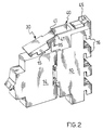
- the body, indicated 10 has a front wall which is shaped so as to form a double rail 12 for the support and engagement of an electrical device 14 which, in the embodiment shown, is a switch ( Figure 2 ), and a rear wall which is shaped so as to form a plurality of hollow hooks 16 for engaging and bearing on corresponding parallel distribution bars, not shown in the drawings. In the embodiment shown, there are four hooks.
- the body 10 houses a metal connector 20 constituted by a metal plate bent and shaped so as to form, at one of its ends, a terminal 22 which projects from the front of the body 10 and, at the opposite end, a U-shaped member 24 disposed inside one of the hooks 16.
- the terminal 22 constitutes a blade contact for engagement in a clip contact which is not shown in the drawings but is accessible on the rear of the device 14, and the U shaped member 24 constitutes an element for electrical and mechanical connection to a bar.
- the connector 20 is intended for contact with the uppermost bar in the drawing but, naturally, it may be formed so as to contact any of the other bars.
- the adaptor comprises a covering element of insulating material mounted for pivoting on the body 10.
- this element is connected to the body 10 of the adaptor by means of a support frame 40 fixed releasably to the body.
- the covering element 30 has a box-like structure, is preferably made of moulded plastics material, and has two parallel sides 31 joined together by an upper wall 32 and by transverse walls 33 which define a seat 34 for the contact terminal 22.
- the covering element 30 is joined to the support frame 40 by means of two aligned pins 35 formed integrally with the box-like structure of the covering element 30.
- the support frame 40 which is also preferably made of moulded plastics material, has two sides 41 joined together by transverse walls 42. Two aligned holes 43 in the sides 41 constitute the seats for the pins 35 of the covering element 30. The edges of two opposed portions of the sides 41 are bent inwardly to form two projections 44 which can be inserted in corresponding opposed grooves 19 provided on the sides of the adaptor body 10.
- a resilient tab 45 which is preferably formed integrally with the frame and which acts as a locking element by snap-engaging a recess provided on the upper side of the body of the adaptor.
- the widths selected for the covering element 30 and for the support frame 40 are such that their sides lie substantially in the same planes as the sides of the body 10 of the adaptor.
- the covering element 30 is held in the protection position, that is, with the contact terminal 22 in the seat 34, by a resilient element and by releasable locking means.
- the resilient element is a tab 39 which is preferably formed integrally with the support frame 40 and the free end of which interferes with a recess provided at one end of the covering element 30.
- the covering element 30 has a pair of curved projections 38 formed in the sides 31 for snap-fitting on one of the rails 12 for the mounting of the electrical device 14 on the adaptor. The projections 38 and the rail 12 thus constitute the means for locking the covering element 30.
- the locking can be released by pushing the covering element with a suitable tool, for example, a screwdriver inserted between the end edge of the covering element 30 and the adaptor body 10 so as to release the covering element from its engagement.
- a suitable tool for example, a screwdriver inserted between the end edge of the covering element 30 and the adaptor body 10 so as to release the covering element from its engagement.
- the covering element 30 is pivoted through 90° about its pivot axis.
- the resilient tab 39 acts on the upper wall of the covering element 30 so as to keep the latter in position.
- a helical spring is disposed on the axis of rotation of the covering element and engages the support frame 40 at one end and the covering element 30 at the other end.
- the covering element 30 can be pivoted through a certain angle towards the closure position until it comes into contact with a side wall of the electrical device 14 ( Figure 2 ). In this position, the covering element 30 covers a recess 15 for access to a terminal normally provided for the electrical connection of the device as an alternative to its engagement on the terminal 22.
- the adaptor according to the invention affords protection against contact with live elements both in the absence of a device mounted on the adaptor, by virtue of the covering of the contact terminal, and with a device mounted thereon, by virtue of the covering of the lateral terminal of the device.
Landscapes
- Engineering & Computer Science (AREA)
- Power Engineering (AREA)
- Connections Arranged To Contact A Plurality Of Conductors (AREA)
- Coupling Device And Connection With Printed Circuit (AREA)
- Details Of Connecting Devices For Male And Female Coupling (AREA)
- Connector Housings Or Holding Contact Members (AREA)
- Switch Cases, Indication, And Locking (AREA)
- Distribution Board (AREA)
Claims (11)
- Adaptateur pour connecter, à des barres de distribution d'énergie électrique, un dispositif électrique (14) du type qui peut être monté sur des rails et qui comporte un contact à pince, l'adaptateur comportant un corps (10) analogue à une boîte qui a une paire de rails (12) disposés sur sa paroi avant pour le montage d'un dispositif électrique (14), de multiples crochets (16) sur sa paroi arrière pour accoupler l'adaptateur à des barres de distribution, et une borne de contact (22) faisant saillie de sa paroi avant pour s'engager dans le contact à pince du dispositif électrique, caractérisé en ce qu'il comporte un élément de recouvrement (30) en matière isolante qui est monté de façon à pivoter sur le corps (10) analogue à une boîte et qui peut adopter une première position dans laquelle il recouvre la borne de contact (22) et une seconde position dans laquelle il laisse la borne de contact (22) découverte pour permettre le montage d'un dispositif électrique (14) sur l'adaptateur, et des moyens (39, 38) qui agissent sur l'élément de recouvrement (30) afin de le maintenir en position sur la borne de contact (22).
- Adaptateur selon la revendication 1, dans lequel les moyens qui agissent sur l'élément de recouvrement (30) comprennent des moyens élastiques (39).
- Adaptateur selon la revendication 1 ou la revendication 2, dans lequel les moyens qui agissent sur l'élément de recouvrement (30) comprennent des moyens de verrouillage libérables (38, 12).
- Adaptateur selon l'une quelconque des revendications précédentes, comportant un bâti (40) fixé de façon amovible au corps (10) analogue à une boîte pour supporter l'élément de recouvrement (30), l'élément de recouvrement (30) étant monté de façon à pivoter sur le bâti de support (40).
- Adaptateur selon la revendication 4, dans la mesure où elle dépend de la revendication 2, dans lequel les moyens élastiques (39) sont fixés au bâti de support (40).
- Adaptateur selon la revendication 4, dans la mesure où elle dépend de la revendication 2, dans lequel les moyens élastiques comprennent un ressort hélicoïdal qui engage le bâti de support (40) par une extrémité et l'élément de recouvrement (30) par l'autre extrémité.
- Adaptateur selon la revendication 4, la revendication 5 ou la revendication 6, dans lequel le corps (10) analogue à une boîte comporte des premiers moyens de fixation (19) sur un côté de ce corps adjacent à la paroi avant, et le bâti de support (40) de l'élément de recouvrement (30) comporte des seconds moyens de fixation (44) correspondant aux premiers.
- Adaptateur selon la revendication 7, dans lequel les premiers moyens de fixation comprennent deux gorges opposées (19) et les seconds moyens de fixation comprennent deux saillies (44) qui peuvent être insérées de façon à glisser dans les gorges opposées.
- Adaptateur selon la revendication 8, comportant un autre élément de verrouillage libérable (45) qui maintient le bâti de support (40) en position sur le corps (10) de l'adaptateur.
- Adaptateur selon la revendication 9, dans lequel l'autre élément de verrouillage (45) comporte une languette élastique (45) fixée par rapport au bâti de support et un évidement situé dans le corps (10) de l'adaptateur.
- Adaptateur selon l'une quelconque des revendications précédentes, à partir de la revendication 3, dans lequel les moyens de verrouillage libérables (38, 12) comprennent deux saillies (38) qui sont formées sur l'élément de recouvrement (30) et qui peuvent être encliquetées sur l'un des rails (12) pour le montage du dispositif (14).
Applications Claiming Priority (2)
| Application Number | Priority Date | Filing Date | Title |
|---|---|---|---|
| ITMI980413 | 1998-03-02 | ||
| IT98MI000413A IT1298455B1 (it) | 1998-03-02 | 1998-03-02 | Adattatore di sicurezza per il collegamento di un apparecchio elettrico a barre di distribuzione |
Publications (3)
| Publication Number | Publication Date |
|---|---|
| EP0940897A2 EP0940897A2 (fr) | 1999-09-08 |
| EP0940897A3 EP0940897A3 (fr) | 1999-09-29 |
| EP0940897B1 true EP0940897B1 (fr) | 2008-04-09 |
Family
ID=11379144
Family Applications (1)
| Application Number | Title | Priority Date | Filing Date |
|---|---|---|---|
| EP99200547A Expired - Lifetime EP0940897B1 (fr) | 1998-03-02 | 1999-02-25 | Adaptateur de sécurité pour la connection d'un appareil électrique à des barres omnibus |
Country Status (6)
| Country | Link |
|---|---|
| EP (1) | EP0940897B1 (fr) |
| AT (1) | ATE392035T1 (fr) |
| DE (1) | DE69938468T2 (fr) |
| ES (1) | ES2306497T3 (fr) |
| IT (1) | IT1298455B1 (fr) |
| PT (1) | PT940897E (fr) |
Family Cites Families (4)
| Publication number | Priority date | Publication date | Assignee | Title |
|---|---|---|---|---|
| DE3537600A1 (de) * | 1985-10-23 | 1987-04-30 | Bbc Brown Boveri & Cie | Abdeckvorrichtung fuer anschlussklemmen von starkstromgeraeten |
| GB8804642D0 (en) * | 1988-02-27 | 1988-03-30 | Delta Electrical Holdings | Electrical supply control apparatus |
| IT1255882B (it) * | 1992-10-16 | 1995-11-17 | Bticino Spa | Adattatore con dispositivo di sicurezza per collegamento a barre di distribuzione elettrica di apparecchiature elettriche a montaggio su rotaia. |
| DE9310753U1 (de) * | 1993-07-17 | 1993-09-30 | Alfred Wöhner GmbH, 96472 Rödental | Sicherungselement für Stromschienensysteme |
-
1998
- 1998-03-02 IT IT98MI000413A patent/IT1298455B1/it active IP Right Grant
-
1999
- 1999-02-25 PT PT99200547T patent/PT940897E/pt unknown
- 1999-02-25 DE DE69938468T patent/DE69938468T2/de not_active Expired - Fee Related
- 1999-02-25 ES ES99200547T patent/ES2306497T3/es not_active Expired - Lifetime
- 1999-02-25 AT AT99200547T patent/ATE392035T1/de not_active IP Right Cessation
- 1999-02-25 EP EP99200547A patent/EP0940897B1/fr not_active Expired - Lifetime
Also Published As
| Publication number | Publication date |
|---|---|
| DE69938468T2 (de) | 2009-05-20 |
| ATE392035T1 (de) | 2008-04-15 |
| ITMI980413A1 (it) | 1999-09-02 |
| EP0940897A3 (fr) | 1999-09-29 |
| ES2306497T3 (es) | 2008-11-01 |
| PT940897E (pt) | 2008-07-14 |
| IT1298455B1 (it) | 2000-01-10 |
| EP0940897A2 (fr) | 1999-09-08 |
| DE69938468D1 (de) | 2008-05-21 |
Similar Documents
| Publication | Publication Date | Title |
|---|---|---|
| US4997386A (en) | Connectors | |
| US5047604A (en) | Adapter providing unitary mounting capability for standard circuit breaker | |
| JP2505296B2 (ja) | 回路しゃ断器補助装置のスナップ嵌めパッケ―ジ | |
| CA2203220A1 (fr) | Alveole comprenant un dispositif de securite | |
| EP3208900B1 (fr) | Dispositif électrique pour montage sur rail | |
| CN111064017B (zh) | 保护导体端子 | |
| CA1138501A (fr) | Bloc de fusibles avec surface d'identification | |
| US6266253B1 (en) | Rack system for insertion of electrical printed circuit board assemblies using centering and contact elements | |
| EP0896351A3 (fr) | Dispositif pour le couplage mécanique d'un relais de surintensité à un contacteur | |
| US5006951A (en) | Lock handle for printed wiring board assemblies and the like | |
| FI81461B (fi) | Anordning foer inkoppling av en hjaelpbrytare. | |
| US6472621B2 (en) | Start-motor assembly | |
| EP0940897A2 (fr) | Adaptateur de sécurité pour la connection d'un appareil électrique à des barres omnibus | |
| US5114360A (en) | Electrical coupling device | |
| AU2003260669B2 (en) | System for locking a connection bar to a modular electrical appliance | |
| US6323448B1 (en) | Circuit breaker stab contact assembly with spring clip | |
| EP0935323B1 (fr) | Adaptateur muni d'un contact protégé, pour la connection d'appareils électriques à des barres de distribution | |
| US5197594A (en) | Arrangement for coupling an auxiliary switch mechanism | |
| EP0593399B1 (fr) | Adaptateur avec un dispositif à griffe de sécurité pour connecter un appareil électrique à des barres d'alimentation omnibus | |
| WO1991016741A1 (fr) | Protection d'un dispositif electrique comprenant une fiche male et une prise femelle | |
| US4724513A (en) | Method of retaining molded case circuit breakers | |
| US4557047A (en) | Retainer for molded case circuit breakers | |
| HK1021917A (en) | An adaptor with a protected contact for connecting electrical devices to distribution bars | |
| EP0944144B1 (fr) | Elément de connection électrique pour la connection entre des barres omnibus et des appareils électriques modulaires | |
| EP0573254A1 (fr) | Boîtier pour une commande |
Legal Events
| Date | Code | Title | Description |
|---|---|---|---|
| PUAI | Public reference made under article 153(3) epc to a published international application that has entered the european phase |
Free format text: ORIGINAL CODE: 0009012 |
|
| PUAL | Search report despatched |
Free format text: ORIGINAL CODE: 0009013 |
|
| AK | Designated contracting states |
Kind code of ref document: A2 Designated state(s): AT BE DE ES FR GB GR IT NL PT |
|
| AX | Request for extension of the european patent |
Free format text: AL;LT;LV;MK;RO;SI |
|
| AK | Designated contracting states |
Kind code of ref document: A3 Designated state(s): AT BE CH CY DE DK ES FI FR GB GR IE IT LI LU MC NL PT SE |
|
| AX | Request for extension of the european patent |
Free format text: AL;LT;LV;MK;RO;SI |
|
| RIC1 | Information provided on ipc code assigned before grant |
Free format text: 6H 02B 1/21 A |
|
| 17P | Request for examination filed |
Effective date: 20000324 |
|
| AKX | Designation fees paid |
Free format text: AT BE DE ES FR GB GR IT NL PT |
|
| GRAP | Despatch of communication of intention to grant a patent |
Free format text: ORIGINAL CODE: EPIDOSNIGR1 |
|
| GRAS | Grant fee paid |
Free format text: ORIGINAL CODE: EPIDOSNIGR3 |
|
| GRAA | (expected) grant |
Free format text: ORIGINAL CODE: 0009210 |
|
| RIN1 | Information on inventor provided before grant (corrected) |
Inventor name: PASSERA, COSTANTINO |
|
| AK | Designated contracting states |
Kind code of ref document: B1 Designated state(s): AT BE DE ES FR GB GR IT NL PT |
|
| REG | Reference to a national code |
Ref country code: GB Ref legal event code: FG4D |
|
| REF | Corresponds to: |
Ref document number: 69938468 Country of ref document: DE Date of ref document: 20080521 Kind code of ref document: P |
|
| REG | Reference to a national code |
Ref country code: GR Ref legal event code: EP Ref document number: 20080401415 Country of ref document: GR |
|
| REG | Reference to a national code |
Ref country code: PT Ref legal event code: SC4A Free format text: AVAILABILITY OF NATIONAL TRANSLATION Effective date: 20080703 |
|
| REG | Reference to a national code |
Ref country code: ES Ref legal event code: FG2A Ref document number: 2306497 Country of ref document: ES Kind code of ref document: T3 |
|
| ET | Fr: translation filed | ||
| PLBE | No opposition filed within time limit |
Free format text: ORIGINAL CODE: 0009261 |
|
| STAA | Information on the status of an ep patent application or granted ep patent |
Free format text: STATUS: NO OPPOSITION FILED WITHIN TIME LIMIT |
|
| 26N | No opposition filed |
Effective date: 20090112 |
|
| PGFP | Annual fee paid to national office [announced via postgrant information from national office to epo] |
Ref country code: AT Payment date: 20090123 Year of fee payment: 11 |
|
| PGFP | Annual fee paid to national office [announced via postgrant information from national office to epo] |
Ref country code: NL Payment date: 20090126 Year of fee payment: 11 Ref country code: DE Payment date: 20090227 Year of fee payment: 11 |
|
| PGFP | Annual fee paid to national office [announced via postgrant information from national office to epo] |
Ref country code: GR Payment date: 20090216 Year of fee payment: 11 |
|
| PGFP | Annual fee paid to national office [announced via postgrant information from national office to epo] |
Ref country code: GB Payment date: 20100128 Year of fee payment: 12 |
|
| REG | Reference to a national code |
Ref country code: NL Ref legal event code: V1 Effective date: 20100901 |
|
| PG25 | Lapsed in a contracting state [announced via postgrant information from national office to epo] |
Ref country code: AT Free format text: LAPSE BECAUSE OF NON-PAYMENT OF DUE FEES Effective date: 20100225 |
|
| PG25 | Lapsed in a contracting state [announced via postgrant information from national office to epo] |
Ref country code: NL Free format text: LAPSE BECAUSE OF NON-PAYMENT OF DUE FEES Effective date: 20100901 |
|
| PG25 | Lapsed in a contracting state [announced via postgrant information from national office to epo] |
Ref country code: DE Free format text: LAPSE BECAUSE OF NON-PAYMENT OF DUE FEES Effective date: 20100901 |
|
| PGFP | Annual fee paid to national office [announced via postgrant information from national office to epo] |
Ref country code: PT Payment date: 20110202 Year of fee payment: 13 |
|
| PGFP | Annual fee paid to national office [announced via postgrant information from national office to epo] |
Ref country code: BE Payment date: 20110127 Year of fee payment: 13 |
|
| PGFP | Annual fee paid to national office [announced via postgrant information from national office to epo] |
Ref country code: ES Payment date: 20110208 Year of fee payment: 13 |
|
| GBPC | Gb: european patent ceased through non-payment of renewal fee |
Effective date: 20110225 |
|
| PG25 | Lapsed in a contracting state [announced via postgrant information from national office to epo] |
Ref country code: GB Free format text: LAPSE BECAUSE OF NON-PAYMENT OF DUE FEES Effective date: 20110225 |
|
| BERE | Be: lapsed |
Owner name: BTICINO S.P.A. Effective date: 20120228 |
|
| REG | Reference to a national code |
Ref country code: PT Ref legal event code: MM4A Free format text: LAPSE DUE TO NON-PAYMENT OF FEES Effective date: 20120827 |
|
| PG25 | Lapsed in a contracting state [announced via postgrant information from national office to epo] |
Ref country code: PT Free format text: LAPSE BECAUSE OF NON-PAYMENT OF DUE FEES Effective date: 20120827 |
|
| PG25 | Lapsed in a contracting state [announced via postgrant information from national office to epo] |
Ref country code: BE Free format text: LAPSE BECAUSE OF NON-PAYMENT OF DUE FEES Effective date: 20120228 |
|
| REG | Reference to a national code |
Ref country code: ES Ref legal event code: FD2A Effective date: 20130709 |
|
| PG25 | Lapsed in a contracting state [announced via postgrant information from national office to epo] |
Ref country code: ES Free format text: LAPSE BECAUSE OF NON-PAYMENT OF DUE FEES Effective date: 20120226 |
|
| REG | Reference to a national code |
Ref country code: FR Ref legal event code: PLFP Year of fee payment: 17 |
|
| PGFP | Annual fee paid to national office [announced via postgrant information from national office to epo] |
Ref country code: IT Payment date: 20150128 Year of fee payment: 17 |
|
| PGFP | Annual fee paid to national office [announced via postgrant information from national office to epo] |
Ref country code: FR Payment date: 20150220 Year of fee payment: 17 |
|
| REG | Reference to a national code |
Ref country code: FR Ref legal event code: ST Effective date: 20161028 |
|
| PG25 | Lapsed in a contracting state [announced via postgrant information from national office to epo] |
Ref country code: IT Free format text: LAPSE BECAUSE OF NON-PAYMENT OF DUE FEES Effective date: 20160225 |
|
| PG25 | Lapsed in a contracting state [announced via postgrant information from national office to epo] |
Ref country code: FR Free format text: LAPSE BECAUSE OF NON-PAYMENT OF DUE FEES Effective date: 20160229 |