EP0940972A2 - Imprimante à deux teintes et procédé de génération de courbe de correction de la densité pour imprimer en deux teintes - Google Patents
Imprimante à deux teintes et procédé de génération de courbe de correction de la densité pour imprimer en deux teintes Download PDFInfo
- Publication number
- EP0940972A2 EP0940972A2 EP99104218A EP99104218A EP0940972A2 EP 0940972 A2 EP0940972 A2 EP 0940972A2 EP 99104218 A EP99104218 A EP 99104218A EP 99104218 A EP99104218 A EP 99104218A EP 0940972 A2 EP0940972 A2 EP 0940972A2
- Authority
- EP
- European Patent Office
- Prior art keywords
- color ink
- image signal
- reflectance
- light color
- image
- Prior art date
- Legal status (The legal status is an assumption and is not a legal conclusion. Google has not performed a legal analysis and makes no representation as to the accuracy of the status listed.)
- Withdrawn
Links
Images



Classifications
-
- H—ELECTRICITY
- H04—ELECTRIC COMMUNICATION TECHNIQUE
- H04N—PICTORIAL COMMUNICATION, e.g. TELEVISION
- H04N1/00—Scanning, transmission or reproduction of documents or the like, e.g. facsimile transmission; Details thereof
- H04N1/40—Picture signal circuits
- H04N1/407—Control or modification of tonal gradation or of extreme levels, e.g. background level
- H04N1/4076—Control or modification of tonal gradation or of extreme levels, e.g. background level dependent on references outside the picture
- H04N1/4078—Control or modification of tonal gradation or of extreme levels, e.g. background level dependent on references outside the picture using gradational references, e.g. grey-scale test pattern analysis
Definitions
- This invention relates to a double-tone printer in which an image is printed in light color ink and dark color ink which are overlapped with each other, and more particularly to a double-tone printer such as a digital stencil printer for professional use which prints a high quality black-and-white image and a method of making a density correction curve for use in a density correction processing of a digital image with double-tone printing.
- a digital stencil printer has been widely used because of its high printing speed and low cost.
- a stencil master is made by bringing a thermal head, provided with an array of heater elements which are selectively heated according to an image to be printed, into contact with a heat-sensitive master material so that the parts of the heat-sensitive master material brought into contact with the heated heater elements are perforated and become ink-permeable and form picture elements.
- gradation is controlled by controlling the density of the dots (picture elements). Accordingly, in a low density region, grain coarseness appears in the image due to a low dot density. Further since it is hard to uniform the size and shape of the dots, rough impression appears in a low density region and an intermediate density region.
- double-tone printing As a method of printing a high quality black-and-white image, there has been a method known as double-tone printing.
- double-tone printing two kinds of stencil masters are made on the basis of an original and printing is effected by use of the stencil masters with light color ink and dark color ink which are similar in hue.
- the light color ink is generally gray ink and the dark color ink is generally black ink.
- to faithfully reproduce the gradation of the original is important, and gradation of an intermediate density region to a high density region which has been hard to reproduce in conventional black-and-white printing can be expressed and depth of an image can be obtained.
- the primary object of the present invention is to provide a double-tone printer in which a print density suitable for suppressing appearance of grain coarseness in a low density region and appearance of rough impression in an intermediate density region can be quickly determined without repetition of trial printings and a high quality printing can be easily effected.
- Another object of the present invention is to provide a method of making density correction curves for double-tone printing rationally in a routinized manner.
- a double-tone printer comprising, as shown in Figure 1, an image input means which inputs an image signal made up of a series of image signal components each representing a picture element on an original,
- the region which can be expressed by the light color ink is printed solely in the light color ink and the region which cannot be expressed solely by the light color ink is printed in both the light color ink and the dark color ink.
- the density correction curves may be calculated by a personal computer and the like and the result of the calculation may be input into the printer, it is preferred that the printer be provided therein with function of making the density correction curves.
- a method of making the density correction curves for the light color and the dark color which are used in a double-tone printer comprising the steps of
- the image signal may be a digital image signal obtained by digitizing an analog image signal read out from an original such as a photography or a document by an image scanner, or a digital image signal representing an image made as a graphic data by a personal computer or the like.
- the reflectance of the image may be measured by use of a colorimeter or by use of an image scanner for reading out the image on the original as a substitute for the colorimeter.
- Calculation of the proportion of the area of the dark color ink and the reflectance of the dark color ink corresponding to the proportion of the area of the dark color ink can be effected by use of equations such as Neugebauer equation which have been known in the field of double-tone printing.
- a double-tone printer having therein a system for making the density correction curves for the light color and the dark color according to the method of the second aspect. That is, the double-tone printer in accordance with the third aspect of the present invention comprises
- a method of making the density correction curves for the light color and the dark color which are used in a double-tone printer comprising the steps of
- the density correction curve for the dark color is made by use of the density correction curve for the light color which has been made before.
- the density correction curve for the dark color is made on the basis of the measured reflectance of the image of a gray scale in the dark color ink over a solid printing in the light color ink.
- a double-tone printer having therein a system for making the density correction curves for the light color and the dark color according to the method of the fourth aspect. That is, the double-tone printer in accordance with the fifth aspect of the present invention comprises
- the density of the picture elements can be higher as compared with in the conventional double-tone printer where the low density is printed both the light color ink and the dark color ink, whereby appearance of grain coarseness in a low density region can be suppressed.
- the density range which cannot be expressed only in the light color ink is constantly printed in both the light color ink and the dark color ink and there is no density range which is printed only in the dark color ink, appearance of rough impression in an intermediate density region can be suppressed. Further even if the image printed in the light color is somewhat shifted from the image printed in the dark color, quality of the printed image is not largely affected, whereby load on the operator is reduced and a high quality printing can be effected quickly and surely.
- the density correction curves for double-tone printing can be made rationally in a routinized manner even by an unskilled operator.
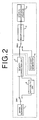
- a double-tone printer in accordance with a first embodiment of the present invention comprises an image scanner 1, a density correction unit 2 and an arithmetic unit 6 which are selectively connected to the image scanner 1 by a switch SW1, a test chart generator 5, a binary-coder 3 which selectively receives output signals from the density correction unit 2 and the test chart generator 5 by way of a switch SW2 and binary-codes the output signal received, and a stencil master making/printer 4 which makes a stencil master on the basis of binary-coded signal and prints the image of the stencil master.
- the stencil master making/printer 4 is provided with a removable ink drum unit and the printing color can be easily changed by changing the ink drum units, e.g., a gray ink (light color ink) drum unit and a black ink (dark color) drum unit. (see, for instance, Japanese Unexamined Patent Publication No. 7(1995)-132671.)
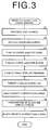
- Figure 3 shows a flow chart for illustrating in brief the processing of making the density correction curves in the double-tone printer of this embodiment.
- test charts are first printed, and the printed test chart is measured for the Y value which is one of the tristimulus values in a XYZ color specification system, whereby a curve representing the relation between the values of image signal components of an image signal and the Y values.
- This curve will be referred to as "the Y value curve", hereinbelow.
- a target print Y value curve is obtained by relating the Y value curve with a preset tone curve, and a gray density correction curve and a black density correction curve are obtained by reverse operations so that the measured Y values conform to target Y values.
- the Y value generally corresponds to brightness or luminous reflectance and substantially correlates with color value of an object.
- the test generator 5 selectively generates a test chart image of a gray scale and a test chart image of a solid image according to a mode selected. By effecting printing in the following manner, three kinds of test printings are obtained.
- the test chart generator 5 When a gray scale printing mode is selected, the test chart generator 5 is connected to the binary-coder 3 through the switch SW2, and a digital image signal representing a gray scale (an image where the values of image signal components vary sequentially) generated by the test chart generator 5 is input into the binary-coder 3.
- the binary-coded image signal is input into the stencil master making/printer 4 and the stencil master/making printer 4 makes a stencil master on the basis of the binary-coded image signal and prints the image of the stencil master.
- the gray scale image is printed in both the gray ink and the black ink, thereby obtaining two printings.
- the test chart generator 5 is connected to the binary-coder 3 through the switch SW2, and a digital image signal representing a solid image (an image consisting of picture elements all of which are represented by image signal components of maximum values) generated by the test chart generator 5 is input into the binary-coder 3.
- the binary-coded image signal is input into the stencil master making/printer 4 and the stencil master/making printer 4 makes a perforated stencil master on the basis of the binary-coded image signal and prints the image of the stencil master.
- the image of the stencil master is first printed in the gray ink and then in the black ink so that the image in the black ink overlaps the image in the gray ink. (step S1)
- step S2 the gray density correction curve ⁇ _g and the black density correction curve ⁇ _k are calculated in a manner to be described later.
- the density correction curves calculated are stored in the density correction unit 2 and are used for density correction when an original read by the image scanner 1 is printed.
- the image scanner 1 doubles an image input means for inputting the image of an original and a colorimeter means for measuring the colors of the test charts.
- the image signal b representing the gray scale print image in the gray ink is stored in a gray image memory 8
- the image signal c representing the gray scale print image in the black ink is stored in a black image memory 9
- the image signal d representing the lap solid image is stored in a lap image memory 10.
- the image signal components of the image signal b representing the gray scale print image in the gray ink are converted to Y values on the basis of a proportionality factor which has been measured and a Y value curve yg(f) for the gray ink shown in Figure 5 is output.
- step S3 The image signal components of the image signal c representing the gray scale print image in the black ink are converted to Y values and a Y value curve yk(h) for the black ink shown in Figure 6 is output.
- step S4 The image signal components of the image signal d representing the lap solid image are converted to Y values and the Y value YGK(i) for the lap printing is output.
- step S5 The image signal components of the image signal d representing the lap solid image are converted to Y values and the Y value YGK(i) for the lap printing is output.
- a desired tone curve which represents the contrast of a target print Y value for a given value of a image signal component of the digital image signal, is preset and stored in a tone curve memory 7.
- the target tone curve is as shown in Figure 7, where Y_max represents a maximum print Y value and Y_min represents a minimum print Y value.
- the target tone curve a stored in the tone curve memory 7 the Y value YGK(i) for the lap printing and the maximum value (the Y value of the printing paper) YW(f') of the Y value curve yg(f) for the gray ink are input into a printing curve calculator 11.
- YW is substituted for the maximum print Y value Y_max and YGK is substituted for the minimum print Y value Y_min, whereby a target print Y value curve y all (e) is calculated and output.
- step S6 The target print Y value curve y all (e) output from the printing curve calculator 11 and the Y value curve yg(f) for the gray ink output from the Y value convertor 12 are input into a gray density correction curve calculator 13.
- the gray density correction curve calculator 13 calculates a gray density correction curve ⁇ _g such as shown in Figure 9 by determining the print Y value for a given value of the image signal component according to the target print Y value curve y all (e) and referring to the Y value curve yg(f) for the gray ink. (step S7) However, in a range where the target print Y value is smaller than the minimum value YG of the Y value curve yg(f) for the gray ink, the value of the image signal component after correction is fixed to 255. That is, since such a range cannot be expressed solely in the gray ink, the range is printed solidly in the gray ink.
- the gray density correction curve ⁇ _g thus calculated is stored in the density correction unit 2 and is used for density correction.
- the Y value y all obtained by lap printing of the gray ink and the black ink is generally represented by the following formula (2) by use of Neugebauer equation.
- AW (1-ag)(1-ak)
- AG ag(1-ak)
- AK (1-ag)ak
- AW represents the proportion of the area of the region where neither of the gray ink and the black ink exists
- AG represents the proportion of the area of the region where only the gray ink exists
- AK represents the proportion of the area of the region where only the black ink exists
- AGK represents the proportion of the area of the region where the gray ink and the black ink overlap each other
- ag represents the proportion of the area of the region where the gray ink exists including the region where the gray ink and the black ink overlap each other
- ak represents the proportion of the area of the region where the black ink exists including the
- Formula (1) is an equation with unknowns ag and ak, and accordingly, when the values of ag and ak are given, the print Y value y all when printing is effected in the gray ink and the black ink in proportions of area of ag and ak can be obtained.
- the Y values which cannot be expressed solely in the gray ink are realized by printing in the black ink over a solid printing in the gray ink.
- Calculated value of ak is substituted in the following formula (3) Yk ⁇ W(1-ak)+Yk ⁇ k and the Y value Yk for the black ink corresponding to the value of ak is calculated.
- Formula (3) is a form of Neugebauer equation applied to monochrome printing. Then the value of the image signal component which gives a Y value equal to the Y value Yk for the black ink calculated is found referring to the Y value curve yk for the black ink, whereby the black density correction curve ⁇ _k shown in Figure 10 is calculated.
- the calculated black density correction curve ⁇ _k(j) is output and stored in the density correction unit 2 and is used for density correction.
- the density correction curves are made by use of three printings, the image of the gray scale printed in the gray ink, the image of the gray scale printed in the black ink and the overlapping solid prints in the gray ink and the black ink, as the test charts.
- the density correction curves may be made by use of an image of the gray scale printed in the gray ink and an image of the gray scale printed in the black ink overlaid on a solid printing in the gray ink as the test charts as in a second embodiment of the present invention described hereinbelow.
- the double-tone printer may be the same as that shown in Figure 2.
- the test chart generator 5 when a gray scale printing mode is selected, the test chart generator 5 is connected to the binary-coder 3 through the switch SW2, and a digital image signal representing a gray scale generated by the test chart generator 5 is input into the binary-coder 3.
- the binary-coded image signal is input into the stencil master making/printer 4 and the stencil master/making printer 4 makes a stencil master on the basis of the binary-coded image signal and prints the image of the stencil master solely in the gray ink, whereby an image of the gray scale in the gray ink is obtained.
- the test chart generator 5 is connected to the binary-coder 3 through the switch SW2, and a digital image signal representing a solid image (an image consisting of picture elements all of which are represented by image signal components of maximum values) generated by the test chart generator 5 is input into the binary-coder 3.
- the binary-coded image signal is input into the stencil master making/printer 4 and the stencil master/making printer 4 makes a stencil master on the basis of the binary-coded image signal and prints the image of the stencil master solely in the gray ink, whereby a solid printing in the gray ink is obtained. Further, the image of the gray scale is printed in the black ink on the solid printing in the gray ink. This printing will be referred to as "the lap printing", hereinbelow.
- the density correction curves are made on the basis of the two printings thus obtained.
- the image scanner 1 is connected to the arithmetic unit 6 through the switch SW1.
- the image scanner 1 reads out the images on the respective printings and the digital image signals representing the two images are stored in the arithmetic unit 6.
- the image signal components of the image signal representing the gray scale print image in the gray ink are converted to Y values on the basis of a proportionality factor which has been measured and a Y value curve yg for the gray ink shown in Figure 5 is obtained.
- the image signal components of the image signal representing the image on the lap printing are converted to Y values and a Y value curve yk2 for lap printing shown in Figure 11 is obtained.
- a desired tone curve which represents the contrast of a target print Y value for a given value of an image signal component of the digital image signal, is preset.
- the target tone curve which gives a linear target print Y value curve y all as shown in Figure 7 is set, where Y_max represents a maximum print Y value and Y_min represents a minimum print Y value.
- the maximum value (the Y value of the printing paper) YW of the Y value curve for the gray ink is substituted for the maximum print Y value Y_max and the minimum value YGK of Y value curve for the lap printing is substituted for the minimum print Y value Y_min, whereby a target print Y value curve y all such as shown in Figure 8 is obtained.
- a gray density correction curve ⁇ _g such as shown in Figure 9 is calculated by determining the print Y value for a given value of the image signal component according to the target print Y value curve y all and referring to the Y value curve yg for the gray ink.
- the black density correction curve can be obtained by obtaining a value of an image signal component which gives a Y value equal to each Y value on the target print Y value curve on the basis of the Y value curve yk2 for the lap printing for the range of the target print Y value curve y all which cannot be expressed solely in the gray ink, and relating the values of the image signal components thus obtained.
- a black density correction curve such as shown in Figure 10 is obtained from the target print Y value curve shown in Figure 8 and the Y value curve yk2 for the lap printing shown in Figure 11.
- optimal density correction curves can be automatically made according to change in the printing conditions such as change in the pressure of the press roller, an extreme change in the environmental temperature, change of the printing paper, change of the inks and the like, whereby printings of high quality can be obtained.
- the double-tone printer need not be provided therein the arithmetic unit.
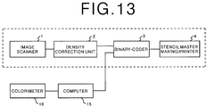
- a computer is connected to the digital stencil printer and a colorimeter is connected to the computer and the density correction curves are made by the computer as shown in Figure 12.
- the computer 15 plays the test chart generator 5 and arithmetic unit 6 in Figure 2, and the colorimeter 16 plays the image scanner 1 and the Y value convertor 12.
- the density correction curves made by the computer 15 is stored in a recording medium such as a ROM and the recording medium is loaded on the density correction unit 2 of the digital stencil printer for use in the density correction.
- the density correction curves can be made by simply causing the system to read the printed test charts, even an unskilled operator can effect double-tone printing at an optimal density, whereby a print density suitable for suppressing appearance of grain coarseness in a low density region and appearance of rough impression in an intermediate density region can be quickly determined without repetition of trial printings and a high quality printing can be easily effected.
- the present invention is especially useful for double-tone printing by a digital stencil printer, the present invention can also be applied to double-tone printing by printers other than the stencil printer.
- a light color density correction curve and a dark color density correction curve suitable for double-tone printing by use of light color ink, dark color ink and printing papers which are designated in advance under a standard printing environment may be stored in a double-tone printer.
- gray ink is employed as the light color ink and black ink is employed as the dark color ink
- other two inks may be employed without limiting to gray and black inks so long as their colors are similar in hue and different in luminance.
Landscapes
- Engineering & Computer Science (AREA)
- Multimedia (AREA)
- Signal Processing (AREA)
- Facsimile Image Signal Circuits (AREA)
- Color Image Communication Systems (AREA)
- Manufacture Or Reproduction Of Printing Formes (AREA)
Applications Claiming Priority (4)
| Application Number | Priority Date | Filing Date | Title |
|---|---|---|---|
| JP5206898 | 1998-03-04 | ||
| JP5206898 | 1998-03-04 | ||
| JP10360740A JPH11317876A (ja) | 1998-03-04 | 1998-12-18 | ダブルトーン印刷装置およびダブルトーン印刷用濃度補正曲線作成方法 |
| JP36074098 | 1998-12-18 |
Publications (2)
| Publication Number | Publication Date |
|---|---|
| EP0940972A2 true EP0940972A2 (fr) | 1999-09-08 |
| EP0940972A3 EP0940972A3 (fr) | 2001-07-04 |
Family
ID=26392672
Family Applications (1)
| Application Number | Title | Priority Date | Filing Date |
|---|---|---|---|
| EP99104218A Withdrawn EP0940972A3 (fr) | 1998-03-04 | 1999-03-02 | Imprimante à deux teintes et procédé de génération de courbe de correction de la densité pour imprimer en deux teintes |
Country Status (3)
| Country | Link |
|---|---|
| US (1) | US6462836B1 (fr) |
| EP (1) | EP0940972A3 (fr) |
| JP (1) | JPH11317876A (fr) |
Cited By (3)
| Publication number | Priority date | Publication date | Assignee | Title |
|---|---|---|---|---|
| EP1946932A4 (fr) * | 2005-11-02 | 2009-09-30 | Dainippon Printing Co Ltd | Dispositif d impression thermique, procede de formation d image et objet imprime |
| EP1980404A4 (fr) * | 2006-01-31 | 2009-09-30 | Dainippon Printing Co Ltd | Dispositif d'impression par transfert thermique et procede de formation d'image |
| CN119359601A (zh) * | 2024-12-24 | 2025-01-24 | 中数智科(杭州)科技有限公司 | 一种用于轨道交通线阵相机采集图像的几何校正方法 |
Families Citing this family (14)
| Publication number | Priority date | Publication date | Assignee | Title |
|---|---|---|---|---|
| JP2000125133A (ja) * | 1998-10-19 | 2000-04-28 | Minolta Co Ltd | 画像処理装置及び画像形成装置並びにこれら両装置からなる画像形成システム並びに画像形成プログラムを記録したコンピュータ読み取り可能な記録媒体並びに画像形成方法 |
| JP4721240B2 (ja) * | 2000-07-28 | 2011-07-13 | 東北リコー株式会社 | 多色孔版印刷方法及び多色孔版印刷装置 |
| US7009733B2 (en) * | 2001-07-02 | 2006-03-07 | Coral Corporation | Manual correction of an image color |
| US7436531B2 (en) * | 2002-05-14 | 2008-10-14 | Xerox Corporation | Systems and methods for using multiple processors for imaging |
| US7033423B2 (en) * | 2003-04-30 | 2006-04-25 | Hewlett-Packard Development Company, L.P. | Gray inks for ink-jet printing |
| US6953239B2 (en) * | 2003-06-13 | 2005-10-11 | Hewlett-Packard Development Company, L.P. | Printer system and printing method |
| US7036919B2 (en) * | 2003-06-13 | 2006-05-02 | Hewlett-Packard Development Company, L.P. | Print Cartridge |
| US7612915B2 (en) * | 2005-10-20 | 2009-11-03 | Hewlett-Packard Development Company, L.P. | Determining composite grays |
| EP1914978A3 (fr) * | 2006-10-19 | 2009-08-19 | Murata Machinery Ltd. | Appareil et procédé de traitement d'images |
| JP4468404B2 (ja) * | 2007-05-02 | 2010-05-26 | キヤノン株式会社 | 情報処理装置の制御方法、情報処理装置及びプログラム |
| JP2012190420A (ja) | 2011-03-14 | 2012-10-04 | Seiko Epson Corp | 画像処理装置および画像処理システム並びに画像処理方法 |
| EP2836903A1 (fr) | 2012-04-12 | 2015-02-18 | Hewlett-Packard Indigo B.V. | Impression avec données de couleur de référence |
| JP7844830B2 (ja) * | 2021-08-03 | 2026-04-14 | 大日本印刷株式会社 | 写真印刷物および写真印刷物の印刷方法 |
| CN116409073B (zh) * | 2021-12-31 | 2025-10-28 | 深圳市汉森软件股份有限公司 | 深浅色油墨混合打印方法、装置、设备及存储介质 |
Family Cites Families (10)
| Publication number | Priority date | Publication date | Assignee | Title |
|---|---|---|---|---|
| FR2604582B1 (fr) * | 1986-09-30 | 1989-01-06 | Bertin & Cie | Procede pour transformer une image initiale de type video a multiples niveaux de gris en une image binaire |
| US5345315A (en) | 1988-11-23 | 1994-09-06 | Imatec, Ltd. | Method and system for improved tone and color reproduction of electronic image on hard copy using a closed loop control |
| US5276459A (en) * | 1990-04-27 | 1994-01-04 | Canon Kabushiki Kaisha | Recording apparatus for performing uniform density image recording utilizing plural types of recording heads |
| JPH04126462A (ja) | 1990-09-18 | 1992-04-27 | Canon Inc | 画像形成装置 |
| JP3213457B2 (ja) | 1993-11-11 | 2001-10-02 | 理想科学工業株式会社 | 孔版印刷装置 |
| US5574544A (en) * | 1994-08-29 | 1996-11-12 | Konica Corporation | Image forming apparatus having image density gradation correction means |
| JP3642081B2 (ja) | 1995-04-14 | 2005-04-27 | 富士ゼロックス株式会社 | 画像記録装置 |
| JP4018755B2 (ja) * | 1995-08-22 | 2007-12-05 | 富士フイルム株式会社 | 色信号変換用トーンカーブ作成方法及び装置 |
| US6178008B1 (en) * | 1997-10-30 | 2001-01-23 | Hewlett-Packard Company | Constructing device-state tables for inkjet printing |
| ATE312146T1 (de) * | 1999-12-27 | 2005-12-15 | Seiko Epson Corp | Tintenset, aufzeichnungsverfahren unter verwendung desselben und aufgezeichnetesbild |
-
1998
- 1998-12-18 JP JP10360740A patent/JPH11317876A/ja active Pending
-
1999
- 1999-03-02 US US09/260,537 patent/US6462836B1/en not_active Expired - Fee Related
- 1999-03-02 EP EP99104218A patent/EP0940972A3/fr not_active Withdrawn
Cited By (4)
| Publication number | Priority date | Publication date | Assignee | Title |
|---|---|---|---|---|
| EP1946932A4 (fr) * | 2005-11-02 | 2009-09-30 | Dainippon Printing Co Ltd | Dispositif d impression thermique, procede de formation d image et objet imprime |
| EP1980404A4 (fr) * | 2006-01-31 | 2009-09-30 | Dainippon Printing Co Ltd | Dispositif d'impression par transfert thermique et procede de formation d'image |
| US8164787B2 (en) | 2006-01-31 | 2012-04-24 | Dai Nippon Printing Co., Ltd. | Thermal transfer recording device and image formation method |
| CN119359601A (zh) * | 2024-12-24 | 2025-01-24 | 中数智科(杭州)科技有限公司 | 一种用于轨道交通线阵相机采集图像的几何校正方法 |
Also Published As
| Publication number | Publication date |
|---|---|
| US6462836B1 (en) | 2002-10-08 |
| JPH11317876A (ja) | 1999-11-16 |
| EP0940972A3 (fr) | 2001-07-04 |
Similar Documents
| Publication | Publication Date | Title |
|---|---|---|
| US6462836B1 (en) | Double-tone printer and method of making density correction curve for double-tone printing | |
| EP0168818B1 (fr) | Appareil à copier pour images en couleurs | |
| EP0706285B1 (fr) | Appareil et procédé de traitement d'images | |
| EP0653879B1 (fr) | Procédé et système de prédiction d'une image de reproduction en couleurs | |
| US5305119A (en) | Color printer calibration architecture | |
| EP0356328B1 (fr) | Procédé de conversion de ton pour images | |
| JPH07281422A (ja) | 濃淡階調が広げられたカラー印刷方法 | |
| JP3360358B2 (ja) | 印刷色材量決定方法 | |
| US6577826B1 (en) | Image forming apparatus which sets parameters for the formation of paper | |
| US7400335B2 (en) | Method for printing a halftone digital image | |
| WO2002065757A1 (fr) | Procede et appareil de reglage d'une image de sortie a partir de donnees d'image | |
| JPH11326056A (ja) | カラープルーファおよびそのキャリブレーション方法 | |
| US20070058224A1 (en) | Image processing apparatus and image processing method | |
| US7280259B2 (en) | Method for printing a color proof using a spatial filter | |
| JP2006135681A (ja) | 画像処理方法および画像処理装置 | |
| CA2117030C (fr) | Methode de reproduction des couleurs utilisee dans un systeme de traitement de donnees d'imagerie a dispositifs d'entree et de sortie independants | |
| JP2002247394A (ja) | 色変換規則作成方法、色変換方法、カラー画像形成装置 | |
| US20050041038A1 (en) | Lookup table for adjusting dot-gain on bitmap files based on average number of dots | |
| JP2932277B2 (ja) | カラー画像記録装置 | |
| US20030072473A1 (en) | Method to determine a characteristic of a printing system | |
| US7595910B2 (en) | Method for making a dot for dot proof | |
| JP4175004B2 (ja) | 画像処理装置 | |
| JP3584474B2 (ja) | 印刷物とカラープリンタ出力物の色を一致させる方法 | |
| JP2787216B2 (ja) | インクジエットプリンタ | |
| EP1596576A2 (fr) | Méthode pour characteriser une boucle fermée |
Legal Events
| Date | Code | Title | Description |
|---|---|---|---|
| PUAI | Public reference made under article 153(3) epc to a published international application that has entered the european phase |
Free format text: ORIGINAL CODE: 0009012 |
|
| 17P | Request for examination filed |
Effective date: 19990302 |
|
| AK | Designated contracting states |
Kind code of ref document: A2 Designated state(s): DE FR GB |
|
| AX | Request for extension of the european patent |
Free format text: AL;LT;LV;MK;RO;SI |
|
| PUAL | Search report despatched |
Free format text: ORIGINAL CODE: 0009013 |
|
| AK | Designated contracting states |
Kind code of ref document: A3 Designated state(s): AT BE CH CY DE DK ES FI FR GB GR IE IT LI LU MC NL PT SE |
|
| AX | Request for extension of the european patent |
Free format text: AL;LT;LV;MK;RO;SI |
|
| AKX | Designation fees paid |
Free format text: DE FR GB |
|
| 17Q | First examination report despatched |
Effective date: 20050628 |
|
| STAA | Information on the status of an ep patent application or granted ep patent |
Free format text: STATUS: THE APPLICATION IS DEEMED TO BE WITHDRAWN |
|
| 18D | Application deemed to be withdrawn |
Effective date: 20051109 |