EP0940981A2 - Kanalwählendes Gerät - Google Patents
Kanalwählendes Gerät Download PDFInfo
- Publication number
- EP0940981A2 EP0940981A2 EP99103910A EP99103910A EP0940981A2 EP 0940981 A2 EP0940981 A2 EP 0940981A2 EP 99103910 A EP99103910 A EP 99103910A EP 99103910 A EP99103910 A EP 99103910A EP 0940981 A2 EP0940981 A2 EP 0940981A2
- Authority
- EP
- European Patent Office
- Prior art keywords
- tuning
- frequency
- channel selection
- selection apparatus
- broadcast
- Prior art date
- Legal status (The legal status is an assumption and is not a legal conclusion. Google has not performed a legal analysis and makes no representation as to the accuracy of the status listed.)
- Granted
Links
Images


Classifications
-
- H—ELECTRICITY
- H04—ELECTRIC COMMUNICATION TECHNIQUE
- H04N—PICTORIAL COMMUNICATION, e.g. TELEVISION
- H04N5/00—Details of television systems
- H04N5/44—Receiver circuitry for the reception of television signals according to analogue transmission standards
- H04N5/50—Tuning indicators; Automatic tuning control
-
- H—ELECTRICITY
- H03—ELECTRONIC CIRCUITRY
- H03J—TUNING RESONANT CIRCUITS; SELECTING RESONANT CIRCUITS
- H03J7/00—Automatic frequency control; Automatic scanning over a band of frequencies
- H03J7/02—Automatic frequency control
-
- H—ELECTRICITY
- H04—ELECTRIC COMMUNICATION TECHNIQUE
- H04N—PICTORIAL COMMUNICATION, e.g. TELEVISION
- H04N21/00—Selective content distribution, e.g. interactive television or video on demand [VOD]
- H04N21/40—Client devices specifically adapted for the reception of or interaction with content, e.g. set-top-box [STB]; Operations thereof
- H04N21/43—Processing of content or additional data, e.g. demultiplexing additional data from a digital video stream; Elementary client operations, e.g. monitoring of home network or synchronising decoder's clock; Client middleware
- H04N21/438—Interfacing the downstream path of the transmission network originating from a server, e.g. retrieving encoded video stream packets from an IP network
- H04N21/4383—Accessing a communication channel
Definitions
- the present invention relates to a channel selection apparatus employed in a television receiver (TV) or a video cassette recorder (VCR), and more particularly to a channel selection apparatus that receives automatically all the broadcast signals available in a given local area with identifying their station names. The channel selection apparatus then sorts the signals in a given order, and has tuning buttons store the signals in the given order.
- TV television receiver
- VCR video cassette recorder
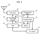
- Fig. 3 is a block diagram illustrating a sorting technique of the channel selection apparatus already commercialized and employed in TVs and VCRs.
- the channel selection apparatus comprises the following elements:
- the construction discussed above allows the channel selection apparatus to assign the frequencies of broadcasting stations of each state or each local area in a specified order to the tuning buttons of TVs or VCRs and to store them in the buttons.
- the arrangement of stored frequencies can be changed so that the frequency of less parity errors can be stored to the tuning button easier for selection.
- field intensities of both the broadcast signals to be compared are strong enough, visual check can hardly distinguish picture qualities of both the signals. It is therefore possible to assign the broadcast signal having a higher parity error rate of text signal to a tuning button easier for selection.
- the foregoing structure can avoid the problem discussed above.
- German Patent No. DE195 18 368 C1 discloses the following technique about determining strength of a television signal based on a quality of a received teletext-signal out of broadcast signals.
- a non-time-varied part is selected from the teletext signals, and this part is compared in a plurality of times.
- the broadcast signals are evaluated based on a number of different points of the comparison results.
- This German patent still has the same problem as discussed previously, i.e. since little errors are expected in a steady state under a practical field intensity, the comparison result is not always correct.
- a channel selection apparatus of the present invention practices the following steps to store a broadcast signal having the least parity errors with priority in a tuning button of an easier selecting operation. First, store in pairs into a memory all the names of broadcasting stations and corresponding frequencies available in the area where the channel selection apparatus is operated. Second, detect the broadcast signals having different frequencies under the same station name from the memory. Receive the detected plural broadcast signals individually with shifting RF frequencies by a predetermined value from the normal frequency so that the field intensity thereof is intentionally lowered. Then, detect only text data out of the received broadcast signals, and compare it with a state of high error rate.
- the operation described above can be automatically practiced, or selectively practiced according to an instruction of a user.
- the strength of receiving-field-intensity correlates more closely with the parity-error-rate.
- frequencies stored in the tuning buttons are resorted so that the frequency having the strongest field intensity and producing the best quality of picture is assigned to and stored in the tuning buttons of easiest selecting operation.
- Fig. 1 is a block diagram of a channel selection apparatus in accordance with the first exemplary embodiment of the present invention.
- tuning voltage generator 12 produces a scan voltage to tuning section 11, which scans all frequencies sequentially from a first channel to a last channel with the scan voltage.
- Tuning section 11 incorporates a voltage-controlled oscillator of which frequency is changed with the scan voltage.
- the tuning section When the tuning frequencies are varied sequentially as described avobe, the tuning section outputs a broadcast signal at the agreement of the scan voltage with a tuning voltage corresponding to the frequency of the RF broadcast signal received by antenna 10.
- Broadcast signal detector 18 detects the signals tapped off from the tuning section 11, and halts the voltage scanning with retaining the voltage.
- Text signal detector 13 extracts text signals out of the detected broadcast signals, then identifies names of broadcasting stations using the text signals, and outputs the names to memory 14.
- PLL phase locked loop
- Memory 14 reads off the frequency retained by tuning voltage generator 12, and stores in memory 14 a set of three elements, i.e. the name of broadcasting station, position of the button selecting the station and the RF frequency. After storing these elements all in one set, resume the scanning with a micro controller (not shown).
- broadcast signal detector 18 detects a broadcast signal, repeat the same procedure to store the frequency and the corresponding station name.
- tuning data table as shown in table 1 is prepared in memory 14.
- sets of a position of tuning button, name of station and corresponding frequency are stored.
- the table thus lists up every broadcast signal receivable in a local area.
- Tuning voltage generator 12 recognizes a frequency of the position instructed through a tuning button of a TV, VCR, or a remote controller thereof. Then generator 12 supplies a tuning voltage corresponding to the RF frequency to tuning section 11. A broadcast signal of a desirable station thus can be received and tuned.
- Sorting of the tuning data table is described hereinafter.
- the micro-computer automatically starts sorting.
- Sorter 16 retrieves the broadcast frequencies having different values under one station name from the first line to the bottom in the table. After the retrieval, the microcomputer controls the following steps.
- FIG. 2 illustrates the sorting process in accordance with the first exemplary embodiment of the present invention.
- the list order has been arranged so that the channel having a higher reliability, in other words, the broadcast signal of a lower parity-error-rate is assigned to the tuning button of easier selecting operation upon the end of the foregoing process.
- the parity error rate is counted of the received-broadcast-signal having a shifted frequency by a specified value.
- the predetermined frequency value "df" can be varied depending on a radio wave situation, whereby a more reliable sorting can be achieved.
- broadcast signal detector 18 can be incorporated into tuning voltage generator 12 so that detector 18 can be saved.
- the correlation between the receiving-field-intensity and the parity error is improved through shifting a tuned frequency from a frequency of normal broadcast signal by a predetermined value.
- sorting reliability is improved, thus a channel of higher reliability can be assigned to a tuning button having a smaller number that is placed at the most convenient place for tuning. In other words, the more reliable channel can be stored in the tuning button of easier selecting operation.
- the foregoing first exemplary embodiment stores all receivable station names and the corresponding frequencies into memory 14, then moves to sorting practice automatically by the microcomputer control.
- the channel selection apparatus in accordance with the second exemplary embodiment of the present invention can determine whether the sorting is practiced or not adaptive to the broadcast signals. Whenever sorter 16 identifies the frequency having less parity errors, the microcomputer displays the frequency or its channel number on a display section for seeking an instruction whether the sorting is practiced or not. When the instruction of "practice” is given from outside, sorter 16 re-write the tuning data table in memory 14, when the instruction of "not practice” is given, sorter 16 moves to the next frequency listed on the table for sorting. This process can avoid missing a reception of the broadcast signal, when the same station has different frequencies having different on-air times on the same program.
Landscapes
- Engineering & Computer Science (AREA)
- Multimedia (AREA)
- Signal Processing (AREA)
- Channel Selection Circuits, Automatic Tuning Circuits (AREA)
- Television Systems (AREA)
Applications Claiming Priority (2)
| Application Number | Priority Date | Filing Date | Title |
|---|---|---|---|
| JP5323598 | 1998-03-05 | ||
| JP05323598A JP3399347B2 (ja) | 1998-03-05 | 1998-03-05 | 録画再生装置 |
Publications (3)
| Publication Number | Publication Date |
|---|---|
| EP0940981A2 true EP0940981A2 (de) | 1999-09-08 |
| EP0940981A3 EP0940981A3 (de) | 2000-05-17 |
| EP0940981B1 EP0940981B1 (de) | 2006-05-17 |
Family
ID=12937155
Family Applications (1)
| Application Number | Title | Priority Date | Filing Date |
|---|---|---|---|
| EP99103910A Expired - Lifetime EP0940981B1 (de) | 1998-03-05 | 1999-03-05 | Kanalwählendes Gerät |
Country Status (5)
| Country | Link |
|---|---|
| US (1) | US6480707B1 (de) |
| EP (1) | EP0940981B1 (de) |
| JP (1) | JP3399347B2 (de) |
| CN (1) | CN1178387C (de) |
| DE (1) | DE69931296T2 (de) |
Cited By (1)
| Publication number | Priority date | Publication date | Assignee | Title |
|---|---|---|---|---|
| EP1104203A3 (de) * | 1999-11-29 | 2001-12-19 | Deutsche Thomson-Brandt Gmbh | Anpassung des Videofrequenzganges |
Families Citing this family (8)
| Publication number | Priority date | Publication date | Assignee | Title |
|---|---|---|---|---|
| DE19932563A1 (de) * | 1999-07-13 | 2001-01-18 | Philips Corp Intellectual Pty | Tuner mit wenigstens einem ersten und einem zweiten Frequenzband |
| US6707508B1 (en) * | 1999-07-16 | 2004-03-16 | Thomson Licensing S.A. | Channel entry for selection of a channel |
| WO2001074064A1 (en) * | 2000-03-28 | 2001-10-04 | Koninklijke Philips Electronics N.V. | Updating transmitter data stored in a preset channel memory |
| JP3731554B2 (ja) * | 2002-03-19 | 2006-01-05 | ソニー株式会社 | 信号処理装置、信号処理方法 |
| JP4026403B2 (ja) * | 2002-04-30 | 2007-12-26 | 日本電気株式会社 | 放送鉄塔選択方法、放送鉄塔選択プログラム及び放送受信装置 |
| JP2005045404A (ja) * | 2003-07-24 | 2005-02-17 | Ricoh Co Ltd | 画像処理装置、画像処理方法およびプログラム |
| CN100355269C (zh) * | 2006-01-20 | 2007-12-12 | 北京广博数字电视科技有限公司 | 数字电视实现频道排序的方法 |
| CN104093068A (zh) * | 2014-07-15 | 2014-10-08 | 深圳市同洲电子股份有限公司 | 一种过滤无信号电视节目的方法以及装置 |
Family Cites Families (21)
| Publication number | Priority date | Publication date | Assignee | Title |
|---|---|---|---|---|
| US3980951A (en) * | 1975-08-13 | 1976-09-14 | Fairchild Camera And Instrument Corporation | Electronic tuning control system for television |
| IT1047373B (it) * | 1975-10-16 | 1980-09-10 | Indesit | Disposizione per selezionare una frequenza ricevibile in un ricevitore di segnali |
| DE3039640A1 (de) | 1980-10-21 | 1982-04-29 | Saba Gmbh, 7730 Villingen-Schwenningen | Verfahren zum automatischen suchlauf und digitalen abspeichern von rundfunk- oder fernsehsenderfrequenzen |
| DE3145407C2 (de) | 1981-11-16 | 1985-10-03 | Interessengemeinschaft für Rundfunkschutzrechte GmbH Schutzrechtsverwertung & Co KG, 4000 Düsseldorf | Verfahren und Einrichtung zum automatischen Programmieren eines Stationsspeichers und zum Voreinstellen eines von dem Stationsspeicher steuerbaren Fernsehempfangs-Tuners |
| US4725886A (en) * | 1983-04-21 | 1988-02-16 | The Weather Channel, Inc. | Communications system having an addressable receiver |
| US4776038A (en) * | 1987-01-21 | 1988-10-04 | Rca Licensing Corporation | Automatic air/cable mode selection apparatus for a television tuner |
| US5393713A (en) * | 1987-07-27 | 1995-02-28 | Prs Corporation | Broadcast receiver capable of automatic station identification and format-scanning based on an internal database updatable over the airwaves with automatic receiver location determination |
| JPH02105788A (ja) | 1988-10-14 | 1990-04-18 | Konami Kogyo Kk | 文字多重放送受信機の自動チユーニング装置 |
| KR900017403A (ko) | 1989-04-28 | 1990-11-16 | 이헌조 | 텔리텍스트 수신 최적 포인트 자동 저장 방법 |
| DE69225992T2 (de) * | 1991-04-01 | 1998-10-22 | Sony Corp | RDS-Empfänger |
| US5701599A (en) * | 1991-07-30 | 1997-12-23 | Casio Computer Co., Ltd. | Broadcast receiving apparatus having selection function of good reception condition in designated program item |
| KR960005932B1 (en) * | 1993-12-22 | 1996-05-03 | Lg Electronics Inc | Channel memory apparatus & method |
| FR2717026B1 (fr) * | 1994-03-01 | 1996-03-29 | Thomson Consumer Electronics | Procédé de programmation de tuner et dispositif de mise en Óoeuvre. |
| US5461427A (en) * | 1994-06-28 | 1995-10-24 | Thomson Consumer Electronics, Inc. | Television receiver having the capability to associate any HDTV and any NTSC channel |
| KR970007893B1 (ko) * | 1994-12-31 | 1997-05-17 | 삼정전자 주식회사 | 선호채널 자동설정장치 |
| JPH08205048A (ja) | 1995-01-25 | 1996-08-09 | Mitsubishi Electric Corp | 自動同調装置 |
| JPH08204594A (ja) * | 1995-01-26 | 1996-08-09 | Pioneer Electron Corp | 放送局関連情報を有するデータベースを備えた受信装置 |
| US5818438A (en) * | 1995-04-25 | 1998-10-06 | Bellsouth Corporation | System and method for providing television services |
| DE19518368C1 (de) * | 1995-05-22 | 1996-02-22 | Mb Video Gmbh | Verfahren und Vorrichtung zur Bewertung der Signalstärke eines mit einem Tuner empfangenen Fernsehsignals |
| KR0153728B1 (ko) * | 1995-11-27 | 1998-11-16 | 김광호 | 채널 자동일치방법 |
| KR100477409B1 (ko) * | 1995-12-21 | 2005-08-29 | 코닌클리케 필립스 일렉트로닉스 엔.브이. | 두신호를비교하기위한수신기,장치및방법 |
-
1998
- 1998-03-05 JP JP05323598A patent/JP3399347B2/ja not_active Expired - Fee Related
-
1999
- 1999-03-05 US US09/264,161 patent/US6480707B1/en not_active Expired - Fee Related
- 1999-03-05 DE DE69931296T patent/DE69931296T2/de not_active Expired - Fee Related
- 1999-03-05 EP EP99103910A patent/EP0940981B1/de not_active Expired - Lifetime
- 1999-03-05 CN CNB991020901A patent/CN1178387C/zh not_active Expired - Fee Related
Cited By (1)
| Publication number | Priority date | Publication date | Assignee | Title |
|---|---|---|---|---|
| EP1104203A3 (de) * | 1999-11-29 | 2001-12-19 | Deutsche Thomson-Brandt Gmbh | Anpassung des Videofrequenzganges |
Also Published As
| Publication number | Publication date |
|---|---|
| CN1235417A (zh) | 1999-11-17 |
| JPH11251875A (ja) | 1999-09-17 |
| EP0940981B1 (de) | 2006-05-17 |
| CN1178387C (zh) | 2004-12-01 |
| DE69931296D1 (de) | 2006-06-22 |
| DE69931296T2 (de) | 2007-04-12 |
| US6480707B1 (en) | 2002-11-12 |
| JP3399347B2 (ja) | 2003-04-21 |
| EP0940981A3 (de) | 2000-05-17 |
Similar Documents
| Publication | Publication Date | Title |
|---|---|---|
| CA1267980A (en) | Television tuning system with provisions for quickly locating active cable channels | |
| US4737993A (en) | Cable broadcast TV receiver with automatic channel search responsive to mode change | |
| US4518993A (en) | Television signal receiving system | |
| US5034819A (en) | Channel selecting apparatus and method used in a television receiving apparatus and capable of memorizing channel data | |
| US6731349B1 (en) | Tuner with at least a first and a second frequency band | |
| US4823387A (en) | Television tuning system with provisions for tuning RF signals with scrambled video information | |
| US5299011A (en) | Method of and apparatus for channel scanning | |
| EP0940981B1 (de) | Kanalwählendes Gerät | |
| CA1154098A (en) | Search type tuning system with direct address channel selection apparatus | |
| WO2001093570A1 (en) | Channel selection apparatus | |
| EP0666691B1 (de) | Automatische Identifizierung und Einrichtung zum Abspeichern von Fernsehkanälen | |
| JPH08195916A (ja) | 放送波チャンネル同調方法 | |
| US5617151A (en) | Automatic broadcasting channel selection method and television receiver adopting the same | |
| KR0176719B1 (ko) | 안정상태 검출 장치를 갖는 동조 시스템 | |
| JPH10233969A (ja) | テレビジョン受像機の選局装置 | |
| JPH10224704A (ja) | 選局装置及びその受信信号レベル判別方法 | |
| EP0396103B1 (de) | Kanalwählendes Gerät | |
| KR20000021581A (ko) | 텔레비젼에서의 최적 채널 자동 선택 방법 | |
| KR950009212B1 (ko) | Vs 튜닝수신시 실제 채널 디스플레이방법 | |
| KR0141527B1 (ko) | F/s방식의 전자튜너를 이용한 채널검출장치 | |
| JP3379696B2 (ja) | テレビジョン受信装置 | |
| KR100215143B1 (ko) | 텔레비젼세트 | |
| KR20000003788A (ko) | 자동 튜닝 시스템에 의한 채널 저장 방법 | |
| KR0147985B1 (ko) | 다중 채널 자동 선국 방법 | |
| JP2725270B2 (ja) | テレビジョン受像機 |
Legal Events
| Date | Code | Title | Description |
|---|---|---|---|
| PUAI | Public reference made under article 153(3) epc to a published international application that has entered the european phase |
Free format text: ORIGINAL CODE: 0009012 |
|
| AK | Designated contracting states |
Kind code of ref document: A2 Designated state(s): DE GB |
|
| AX | Request for extension of the european patent |
Free format text: AL;LT;LV;MK;RO;SI |
|
| PUAL | Search report despatched |
Free format text: ORIGINAL CODE: 0009013 |
|
| AK | Designated contracting states |
Kind code of ref document: A3 Designated state(s): AT BE CH CY DE DK ES FI FR GB GR IE IT LI LU MC NL PT SE |
|
| AX | Request for extension of the european patent |
Free format text: AL;LT;LV;MK;RO;SI |
|
| 17P | Request for examination filed |
Effective date: 20000814 |
|
| AKX | Designation fees paid |
Free format text: DE GB |
|
| GRAP | Despatch of communication of intention to grant a patent |
Free format text: ORIGINAL CODE: EPIDOSNIGR1 |
|
| GRAS | Grant fee paid |
Free format text: ORIGINAL CODE: EPIDOSNIGR3 |
|
| GRAA | (expected) grant |
Free format text: ORIGINAL CODE: 0009210 |
|
| AK | Designated contracting states |
Kind code of ref document: B1 Designated state(s): DE GB |
|
| REG | Reference to a national code |
Ref country code: GB Ref legal event code: FG4D |
|
| RIN1 | Information on inventor provided before grant (corrected) |
Inventor name: SAKAI, RYUICHI Inventor name: HIROSE, KOJI |
|
| REF | Corresponds to: |
Ref document number: 69931296 Country of ref document: DE Date of ref document: 20060622 Kind code of ref document: P |
|
| PGFP | Annual fee paid to national office [announced via postgrant information from national office to epo] |
Ref country code: GB Payment date: 20070228 Year of fee payment: 9 |
|
| PGFP | Annual fee paid to national office [announced via postgrant information from national office to epo] |
Ref country code: DE Payment date: 20070301 Year of fee payment: 9 |
|
| PLBE | No opposition filed within time limit |
Free format text: ORIGINAL CODE: 0009261 |
|
| STAA | Information on the status of an ep patent application or granted ep patent |
Free format text: STATUS: NO OPPOSITION FILED WITHIN TIME LIMIT |
|
| 26N | No opposition filed |
Effective date: 20070220 |
|
| GBPC | Gb: european patent ceased through non-payment of renewal fee |
Effective date: 20080305 |
|
| PG25 | Lapsed in a contracting state [announced via postgrant information from national office to epo] |
Ref country code: DE Free format text: LAPSE BECAUSE OF NON-PAYMENT OF DUE FEES Effective date: 20081001 |
|
| PG25 | Lapsed in a contracting state [announced via postgrant information from national office to epo] |
Ref country code: GB Free format text: LAPSE BECAUSE OF NON-PAYMENT OF DUE FEES Effective date: 20080305 |