EP0941012A2 - Dispositif de fixation pour la fixation d'un microphone à un instrument de musique - Google Patents
Dispositif de fixation pour la fixation d'un microphone à un instrument de musique Download PDFInfo
- Publication number
- EP0941012A2 EP0941012A2 EP99100992A EP99100992A EP0941012A2 EP 0941012 A2 EP0941012 A2 EP 0941012A2 EP 99100992 A EP99100992 A EP 99100992A EP 99100992 A EP99100992 A EP 99100992A EP 0941012 A2 EP0941012 A2 EP 0941012A2
- Authority
- EP
- European Patent Office
- Prior art keywords
- section
- clamping
- sections
- fastening device
- musical instrument
- Prior art date
- Legal status (The legal status is an assumption and is not a legal conclusion. Google has not performed a legal analysis and makes no representation as to the accuracy of the status listed.)
- Granted
Links
Images

Classifications
-
- H—ELECTRICITY
- H04—ELECTRIC COMMUNICATION TECHNIQUE
- H04R—LOUDSPEAKERS, MICROPHONES, GRAMOPHONE PICK-UPS OR LIKE ACOUSTIC ELECTROMECHANICAL TRANSDUCERS; ELECTRIC HEARING AIDS; PUBLIC ADDRESS SYSTEMS
- H04R1/00—Details of transducers, loudspeakers or microphones
- H04R1/08—Mouthpieces; Microphones; Attachments therefor
Definitions
- the invention relates to a fastening device for fastening a microphone or a microphone capsule on a musical instrument.
- Such a fastening device is known, with which a microphone is connected Musical instrument, in particular attached to a funnel of a wind instrument can be.
- the fastening devices used in practice Art have a complex construction from several components. Furthermore are the geometric dimensions of the fasteners in comparison to the progressively miniaturization of microphones usually disproportionately large.
- the object of the present invention is the fastening device of the entry mentioned type in such a way that it is a simple and compact Construction.
- the fastening device has two clamping sections, a section of the musical instrument between them under spring force can be clamped, a connecting section with which both clamping sections are resiliently connected to one end, a holding member for attaching the Microphones or the microphone capsule on the fastening device and each contains an actuating section on the clamping sections, being in the unused State of the fastening device 1 of the actuating section z. B. 11 on the one z. B. 5 of the two clamping sections 3, 5 in the direction z. B. 15 of this clamping section z. B. 5 when pinching a section of the musical instrument formed spring force the other clamping section z. B. 3 protrudes at least partially and at least one of the clamping sections at least is made in two parts and the sections are essentially laterally extend apart from each other from the connecting portion and the other Clamping section is at least partially arranged between the sections.
- the advantages of the invention are, in particular, that by the clamping sections provided operating sections an extremely compact and at the same time simple construction is achieved. Furthermore, the fastening device easy to handle by squeezing the actuating sections is opened. This allows the fastening device according to the invention attached or detached to a musical instrument without damaging the material, without the musical instrument being scratched or otherwise damaged at this point becomes. Due to the multi-part design of the clamping sections each section to some extent independent of the other section of the corresponding clamping section. As a result, the fastening device lies even at curved contact surfaces in several places the musical instrument. The fastening device therefore also offers different musical instruments, especially with different radii of curvature the funnel of wind instruments, a secure hold.
- the actuating sections are arranged in the vicinity of the connecting section. Thereby sits the section of the musical instrument to which the fastening device is attached brought as far as possible between the fastening sections. This ensures a secure hold of the fastening device and thus the microphone, even if the musical instrument should be moved quickly, for example.
- the fastening device is in one piece executed and preferably consists essentially of an elastic Material. On the one hand, this increases the structure of the fastening device Simplified and at the same time further reduced the manufacturing effort.
- the first clamping section made in two parts.
- the sections extend in substantially parallel and laterally spaced apart from the connecting section.
- the second clamping section is made in one piece and essentially arranged between the sections of the first clamping section.
- the fastening device it is possible in a particularly advantageous manner Fastening device in a closed position of the clamping sections to produce in one piece, for example by casting and / or stamping.
- the fastening device can be done by squeezing the complementary operating sections against the spring tension given by the elasticity of the material be opened. By suitable shaping of the clamping sections the restoring force of the clamping sections can be influenced within wide limits.
- the free one End of the clamping sections to a predetermined extent against the direction of the associated clamping section when clamping a section of the Musical instrument formed spring force curved to attach the fastening device on a musical instrument.
- the outward curved Ends of the clamping sections essentially serve as guide sections.
- the fastening device on the respective side of the clamping sections, that between the clamping sections pinched section of the musical instrument Locking lugs are provided to prevent the fastening device from slipping off to prevent from the musical instrument.
- the locking lugs thus extend of the clamping sections in their respective direction of the spring force by the Restoring force of the clamping sections is given.
- the locking lugs reach behind in an assembled state, for example, a flange on the funnel edge Brass instrument.
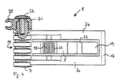
- the fastening device 1 shown by way of example in FIGS. 1 to 4 for Attach a microphone to a musical instrument, especially one Funnel of a wind instrument comprises two essentially rod-shaped or bar-shaped Clamping sections 3 and 5, a connecting section 7, with which both Clamping sections 3 and 5 are resiliently connected to one end and a Holding member 25 (not shown in FIGS. 2 and 3) for attaching a microphone on the fastening device.
- the clamping section 3 executed in two parts and comprises two sections 3a and 3b.
- the Sections 3a and 3b are substantially parallel and laterally from each other spaced apart and extending from the end portions of the connecting portion 7 transverse to its longitudinal direction.
- the sections 3a and 3b are opposite to the connecting section 7 Ends by a substantially parallel to the connecting portion 7 web-shaped end section 17 connected to each other.
- the other clamping section 5 is based on the connecting section 7 in essentially between the sections 3a and 3b of the two-part clamping section 3 arranged.
- the clamping section 5 is compared to the clamping section 3 shorter, so that its end section 19 does not match the transverse one End section 17 of the clamping section 3 can collide.
- the operating sections 9a and 9b of the sections 3a and 3b extend in the direction of force 13 of the clamping section 3 to the outside. They tower in a closed position of the fastening device 1 in the same Direction of force 13 pointing, substantially flat side surface of the other Clamping section 5 (see Fig. 1). Conversely, the operating section extends 11 of the clamping section 5 in the direction of force 15 of the clamping section 5 and in the closed position protrudes above the fastening device 1 those in the direction of force 15 facing, substantially flat side surfaces of the Sub-sections 3a and 3b of the clamping section 3 (Fig. 1).
- the actuating sections 9a, 9b and 11 are on the clamping sections 3 and 5 several, essentially across the entire width of the clamping sections 3 and 5 extending elongated bulges 27 are provided, the one serve safe actuation of the fastening device.
- the width of the clamping sections 3 and 5 somewhat reduced.
- the connecting section 7 is in one piece with in the illustrated embodiment the clamping sections 3 and 5 executed and has essentially the shape of a cylinder, which is at right angles to the clamping sections 3 and 5 extends and on its circumference with several spaced apart, in substantially circumferential grooves 29 is provided, the cylinder axis in illustrated embodiment approximately with the pivot axis of the two clamping sections 3 and 5 coincides.
- the holding member 25 has the shape of a sleeve with a longitudinally extending Groove.
- the holding member 25 is transverse to the longitudinal direction of the connecting section 7 attached to a rotary section 31 which is substantially cylindrical and is of the same diameter as the connecting section 7 connects unilaterally in its longitudinal direction.
- the rotary section 31 is relative to the connecting section 7 rotatably mounted about an axis 26, which is one-sided in the longitudinal direction centrally from the cylindrical connecting section 7 extends.
- a bolt 32 with a wide head sits on the outer end of the Axis 26. The wide head of the bolt prevents the rotary section 31 from the attached holding member 25 can slide from the axis 26.
Landscapes
- Physics & Mathematics (AREA)
- Engineering & Computer Science (AREA)
- Acoustics & Sound (AREA)
- Signal Processing (AREA)
- Details Of Audible-Bandwidth Transducers (AREA)
- Clamps And Clips (AREA)
Applications Claiming Priority (2)
| Application Number | Priority Date | Filing Date | Title |
|---|---|---|---|
| DE19804315 | 1998-02-04 | ||
| DE19804315A DE19804315C1 (de) | 1998-02-04 | 1998-02-04 | Befestigungsvorrichtung zum Befestigen eines Mikrofons an einem Musikinstrument |
Publications (3)
| Publication Number | Publication Date |
|---|---|
| EP0941012A2 true EP0941012A2 (fr) | 1999-09-08 |
| EP0941012A3 EP0941012A3 (fr) | 2000-07-12 |
| EP0941012B1 EP0941012B1 (fr) | 2003-04-16 |
Family
ID=7856587
Family Applications (1)
| Application Number | Title | Priority Date | Filing Date |
|---|---|---|---|
| EP99100992A Expired - Lifetime EP0941012B1 (fr) | 1998-02-04 | 1999-01-21 | Dispositif de fixation pour la fixation d'un microphone à un instrument de musique |
Country Status (5)
| Country | Link |
|---|---|
| US (1) | US6149114A (fr) |
| EP (1) | EP0941012B1 (fr) |
| JP (1) | JP3987225B2 (fr) |
| CA (1) | CA2260615A1 (fr) |
| DE (2) | DE19804315C1 (fr) |
Families Citing this family (6)
| Publication number | Priority date | Publication date | Assignee | Title |
|---|---|---|---|---|
| DE29900579U1 (de) * | 1999-01-15 | 1999-04-01 | Sennheiser electronic GmbH & Co. KG, 30900 Wedemark | Klemmhalterung |
| NL1013981C2 (nl) * | 1999-12-29 | 2001-07-02 | Sound Specialties S & D | Instrumentenklem. |
| US6527237B2 (en) | 2001-07-02 | 2003-03-04 | Harman International Industries Incorporated | Crossbar bracket assembly for speakers and monitors |
| DE102009010723B4 (de) | 2009-02-27 | 2012-11-29 | Beyerdynamic Gmbh & Co. Kg | Haltevorrichtung |
| US9832558B2 (en) * | 2016-01-12 | 2017-11-28 | Robert Carroll Smith | Anti-shock self-powered microphone and monitor system for wind instruments and a mount therefor |
| CN114584898B (zh) * | 2020-12-01 | 2025-05-06 | 佳乐电子股份有限公司 | 乐器夹具 |
Family Cites Families (10)
| Publication number | Priority date | Publication date | Assignee | Title |
|---|---|---|---|---|
| US344567A (en) * | 1886-06-29 | William b | ||
| US3883926A (en) * | 1973-11-23 | 1975-05-20 | Rodney Kent Reynolds | Flexible hanger clamp for electrical lamp socket |
| US5371991A (en) * | 1987-12-07 | 1994-12-13 | Bechtel; Richard | Re-bar clamp assembly |
| DE3920865A1 (de) * | 1989-06-01 | 1991-02-21 | Klaus Winkler | Hohler saitenhalterknopf fuer die aufnahme eines mikrofons zur elektroakustischen verstaerkung von streichinstrumenten |
| NL8902391A (nl) * | 1989-09-26 | 1991-04-16 | Serge Schrier | Microfoonbevestigingsconstructie voor blaasinstrument. |
| US5354026A (en) * | 1993-04-29 | 1994-10-11 | Bulla Wesley A | Portable self-leveling clamp-on utility hook |
| JP2865030B2 (ja) * | 1994-11-14 | 1999-03-08 | ヤマハ株式会社 | 金管楽器用消音器 |
| DE29518362U1 (de) * | 1995-11-18 | 1997-03-20 | Sennheiser Electronic Kg, 30900 Wedemark | Mikrofonhalter |
| US5833186A (en) * | 1996-01-18 | 1998-11-10 | Labtec Enterprises, Inc. | Combination speaker housing and video monitor bracket |
| DE29614188U1 (de) * | 1996-08-16 | 1996-10-02 | Sennheiser electronic GmbH & Co. KG, 30900 Wedemark | Mikrofonhalterung |
-
1998
- 1998-02-04 DE DE19804315A patent/DE19804315C1/de not_active Expired - Fee Related
-
1999
- 1999-01-21 DE DE59905028T patent/DE59905028D1/de not_active Expired - Lifetime
- 1999-01-21 EP EP99100992A patent/EP0941012B1/fr not_active Expired - Lifetime
- 1999-02-03 US US09/243,050 patent/US6149114A/en not_active Expired - Fee Related
- 1999-02-03 CA CA002260615A patent/CA2260615A1/fr not_active Abandoned
- 1999-02-04 JP JP02725899A patent/JP3987225B2/ja not_active Expired - Fee Related
Also Published As
| Publication number | Publication date |
|---|---|
| DE19804315C1 (de) | 1999-04-08 |
| JP3987225B2 (ja) | 2007-10-03 |
| CA2260615A1 (fr) | 1999-08-04 |
| JPH11275671A (ja) | 1999-10-08 |
| DE59905028D1 (de) | 2003-05-22 |
| EP0941012A3 (fr) | 2000-07-12 |
| US6149114A (en) | 2000-11-21 |
| EP0941012B1 (fr) | 2003-04-16 |
Similar Documents
| Publication | Publication Date | Title |
|---|---|---|
| EP2961899B1 (fr) | Poignée de commande | |
| DE102016111324B4 (de) | Spannvorrichtung | |
| DE3110776A1 (de) | Geraet zum treiben einer schraube, eines stifts, eines niets o.dgl. | |
| DE102020127061A1 (de) | Umschaltelement für Ratschenschlüssel | |
| DE19901662B4 (de) | Spannfutter für Bits oder dergleichen | |
| EP2476500B1 (fr) | Dispositif d'approvisionnement en fil de soudage | |
| EP0941012B1 (fr) | Dispositif de fixation pour la fixation d'un microphone à un instrument de musique | |
| DE3829109A1 (de) | Elektrischer schalter, insbesondere lenstockschalter fuer kratfahrzeuge | |
| EP0106299B1 (fr) | Elément sélecteur pour semoir de précision pneumatique | |
| EP1080844B1 (fr) | Pince | |
| EP4314448A1 (fr) | Poignée d'actionnement | |
| DE2657905A1 (de) | Verbindung zwischen den kettengliedern einer gleiskette | |
| DE19730269C2 (de) | Vorrichtung zum Befestigen eines ersten Teils mit einem zweiten Teil | |
| DE69415703T2 (de) | Bandschlüssel, insbesondere für Fahrzeug-Ölfilter | |
| EP0824996A1 (fr) | Pince à ouverture variable | |
| EP2554857A1 (fr) | Dispositif destiné à la fixation d'une tige filetée | |
| EP2578891B1 (fr) | Adapteur | |
| EP0984119B1 (fr) | Axe à ressort, notamment un carré de poignée | |
| DE10330479A1 (de) | Scharnierbandkette | |
| DE1563730C3 (de) | Einarmige Sicherungszange | |
| DE102010046657B4 (de) | Stift mit Klemmbereich | |
| WO2025124861A1 (fr) | Dispositif de fixation | |
| DE9318816U1 (de) | Instrument für chirurgische Zwecke | |
| DE102021215064A1 (de) | Verpackungsvorrichtung für eine Zubehörvorrichtung | |
| EP3636863A1 (fr) | Fixation de joint |
Legal Events
| Date | Code | Title | Description |
|---|---|---|---|
| PUAI | Public reference made under article 153(3) epc to a published international application that has entered the european phase |
Free format text: ORIGINAL CODE: 0009012 |
|
| AK | Designated contracting states |
Kind code of ref document: A2 Designated state(s): DE GB |
|
| AX | Request for extension of the european patent |
Free format text: AL;LT;LV;MK;RO;SI |
|
| PUAL | Search report despatched |
Free format text: ORIGINAL CODE: 0009013 |
|
| AK | Designated contracting states |
Kind code of ref document: A3 Designated state(s): AT BE CH CY DE DK ES FI FR GB GR IE IT LI LU MC NL PT SE |
|
| AX | Request for extension of the european patent |
Free format text: AL;LT;LV;MK;RO;SI |
|
| 17P | Request for examination filed |
Effective date: 20010112 |
|
| AKX | Designation fees paid |
Free format text: DE GB |
|
| GRAH | Despatch of communication of intention to grant a patent |
Free format text: ORIGINAL CODE: EPIDOS IGRA |
|
| GRAH | Despatch of communication of intention to grant a patent |
Free format text: ORIGINAL CODE: EPIDOS IGRA |
|
| GRAA | (expected) grant |
Free format text: ORIGINAL CODE: 0009210 |
|
| AK | Designated contracting states |
Designated state(s): DE GB |
|
| REG | Reference to a national code |
Ref country code: GB Ref legal event code: FG4D Free format text: NOT ENGLISH |
|
| GBT | Gb: translation of ep patent filed (gb section 77(6)(a)/1977) |
Effective date: 20030416 |
|
| REF | Corresponds to: |
Ref document number: 59905028 Country of ref document: DE Date of ref document: 20030522 Kind code of ref document: P |
|
| PLBE | No opposition filed within time limit |
Free format text: ORIGINAL CODE: 0009261 |
|
| STAA | Information on the status of an ep patent application or granted ep patent |
Free format text: STATUS: NO OPPOSITION FILED WITHIN TIME LIMIT |
|
| 26N | No opposition filed |
Effective date: 20040119 |
|
| PGFP | Annual fee paid to national office [announced via postgrant information from national office to epo] |
Ref country code: GB Payment date: 20080123 Year of fee payment: 10 |
|
| GBPC | Gb: european patent ceased through non-payment of renewal fee |
Effective date: 20090121 |
|
| PG25 | Lapsed in a contracting state [announced via postgrant information from national office to epo] |
Ref country code: GB Free format text: LAPSE BECAUSE OF NON-PAYMENT OF DUE FEES Effective date: 20090121 |
|
| PGFP | Annual fee paid to national office [announced via postgrant information from national office to epo] |
Ref country code: DE Payment date: 20130123 Year of fee payment: 15 |
|
| REG | Reference to a national code |
Ref country code: DE Ref legal event code: R119 Ref document number: 59905028 Country of ref document: DE |
|
| REG | Reference to a national code |
Ref country code: DE Ref legal event code: R119 Ref document number: 59905028 Country of ref document: DE Effective date: 20140801 |
|
| PG25 | Lapsed in a contracting state [announced via postgrant information from national office to epo] |
Ref country code: DE Free format text: LAPSE BECAUSE OF NON-PAYMENT OF DUE FEES Effective date: 20140801 |