EP0941437B1 - Systeme de desassemblage rapide pour un reservoir rempli d'un fluide, sans fuite et sans event - Google Patents
Systeme de desassemblage rapide pour un reservoir rempli d'un fluide, sans fuite et sans event Download PDFInfo
- Publication number
- EP0941437B1 EP0941437B1 EP97949598A EP97949598A EP0941437B1 EP 0941437 B1 EP0941437 B1 EP 0941437B1 EP 97949598 A EP97949598 A EP 97949598A EP 97949598 A EP97949598 A EP 97949598A EP 0941437 B1 EP0941437 B1 EP 0941437B1
- Authority
- EP
- European Patent Office
- Prior art keywords
- quick disconnect
- outlet
- disconnect according
- passageway
- umbrella valve
- Prior art date
- Legal status (The legal status is an assumption and is not a legal conclusion. Google has not performed a legal analysis and makes no representation as to the accuracy of the status listed.)
- Expired - Lifetime
Links
Images

Classifications
-
- F—MECHANICAL ENGINEERING; LIGHTING; HEATING; WEAPONS; BLASTING
- F16—ENGINEERING ELEMENTS AND UNITS; GENERAL MEASURES FOR PRODUCING AND MAINTAINING EFFECTIVE FUNCTIONING OF MACHINES OR INSTALLATIONS; THERMAL INSULATION IN GENERAL
- F16L—PIPES; JOINTS OR FITTINGS FOR PIPES; SUPPORTS FOR PIPES, CABLES OR PROTECTIVE TUBING; MEANS FOR THERMAL INSULATION IN GENERAL
- F16L37/00—Couplings of the quick-acting type
- F16L37/08—Couplings of the quick-acting type in which the connection between abutting or axially overlapping ends is maintained by locking members
- F16L37/084—Couplings of the quick-acting type in which the connection between abutting or axially overlapping ends is maintained by locking members combined with automatic locking
- F16L37/0841—Couplings of the quick-acting type in which the connection between abutting or axially overlapping ends is maintained by locking members combined with automatic locking by means of a transversally slidable locking member surrounding the tube
-
- F—MECHANICAL ENGINEERING; LIGHTING; HEATING; WEAPONS; BLASTING
- F16—ENGINEERING ELEMENTS AND UNITS; GENERAL MEASURES FOR PRODUCING AND MAINTAINING EFFECTIVE FUNCTIONING OF MACHINES OR INSTALLATIONS; THERMAL INSULATION IN GENERAL
- F16K—VALVES; TAPS; COCKS; ACTUATING-FLOATS; DEVICES FOR VENTING OR AERATING
- F16K15/00—Check valves
- F16K15/18—Check valves with actuating mechanism; Combined check valves and actuated valves
- F16K15/182—Check valves with actuating mechanism; Combined check valves and actuated valves with actuating mechanism
- F16K15/1825—Check valves with actuating mechanism; Combined check valves and actuated valves with actuating mechanism for check valves with flexible valve members
Definitions
- This invention relates to the field of quick disconnects, and more particularly, to a non-leaking, non-venting quick disconnect system for an inverted liquid filled canister.
- cleaning implements such as mops
- a canister attached to a liquid delivery system containing a sprayer nozzle to dispense cleaning fluid in the vicinity of a disposable pad attached to a cleaning head member.
- These devices typically use a removable canister which is inserted within a receptacle (housing) attached to the device's handle.
- receptacle housing
- these canister and receptacle systems have numerous problems. For example, these canister's typically leak before and after loading, particularly when the canister is inverted.
- these canisters must be loaded into the receptacle by twisting or turning the canister using conventional threading. After loading, these canisters typically require venting to dispense their contents properly. For at least these reasons, current canister liquid delivery systems are inefficient and inconvenient.
- a quick disconnect system which comprises a first member having an outlet with at least one passageway, a valve movably attached within said outlet for sealing said passageway, and a second member having an inlet.
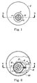
- FIG. 1 is a top view of the preferred outlet according to the preferred embodiment of the present invention.
- FIG. 2 is a top view of the preferred inlet according to the preferred embodiment of the present invention.
- FIG. 3 is a rotated cross sectional view of the umbrella valve seated within the outlet taken along line 3-3 of FIG. 1 according to the preferred embodiment of the present invention.
- FIG. 4 is a rotated cross sectional view of the spring activated push button lock and inlet taken along line 4-4 of FIG. 2 according to the preferred embodiment of the present invention.
- FIG. 5 is a rotated cross sectional view of the first and second members engaged according to the preferred embodiment of the present invention.
- the preferred non-leaking quick disconnect 1 includes a first member 2 having an outlet 3 (FIGS. 1 and 3) with at least one passageway 4, a flexible umbrella valve 5 positioned within the outlet 3 for sealing the passageway 4, and a second member 6 having an inlet 7 (FIGS. 2 and 4) with at least one finger 8.
- a spring 9 activated push button 10 locking mechanism 11 releasably snap locks the first member 2 and second member 6 together.
- the locking mechanism 11 preferably has a snap-lock 12 which engages a guide slot 13 of the second member 6 and releasably engages an indentation 14 of the first member 2 when the first and second members 2, 6 are removably engaged.
- the outlet 3 is radially offset from the first member 2 and has a chamfered exterior 15 for guiding the outlet 3 within the second member 6.
- the inlet 7 is radially offset from a housing 20 which supports the first member 2 and the bottle 16
- the first member 2 is preferably a liquid filled canister.
- the umbrella valve 5 seals the liquid within the first member 2.
- the umbrella valve 5 is biased in a closed or sealed position (FIG. 3) due to the spring force of the umbrella valve 5 in the assembled, inherently pre-loaded condition.
- the hydrostatic force of the liquid ensures a tight seal and the liquid remains within the first member 2 without leaking through the outlet 3.
- the first member 2 preferably includes a collapsible bottle 16 for supplying the liquid to the outlet 3, thus avoiding the need to provide a vent within the first member 2.
- the non-vented collapsible bottle 16 allows the liquid to be dispensed in any orientation as long as a force is exerted on the bottle 16 from, for example, gravity, a pumping mechanism or manually squeezing the bottle 16.
- An O-ring 17 prevents the liquid from leaking through the outlet 3 prior to the first member 2 being properly seated within the second member 6.
- the O-ring 17 -engages an exterior surface 18, above the serrations 19, of the outlet 3 upon engagement of the first and second members 2, 6.
- the surface 18 has serrations 19 which reduce the likelihood that the umbrella valve 5 from being pulled through the passageways 4 due to the suction created when the first member 2 is disengaged from the second member 6.
- the valve 5 is formed of a silicon polymer in the shape of an umbrella but may be formed in a variety of shapes and materials without deviating from the intent of the invention.
- the valve 5 may be a spring-loaded ball valve.
- the umbrella valve 5 comprises a stem 5a and umbrella skirt 5b, both of which are preferably inherently pre-loaded.
- the offset outlet 3 of the first member 2 is inserted within the offset inlet 7 of the second member 6 (FIG. 5). Since both the outlet 3 and the inlet 7 are radially offset, the outlet 3 and the inlet 7 are axially aligned upon engagement with the first and second members 2, 6.
- the chamfered exterior 15 of the first member 2 automatically guides the first and second members 2, 6 upon insertion of the first member 2 within the second member 6. After insertion, the chamfered exterior 15 engages the snap lock 12, partially compressing the spring 9 and displacing the snap lock 12 along the guide slot 13. Meanwhile, the surface 18 engages the O-ring 17 which creates a seal prior to the fingers 8 entering the passageways 4 and displacing the skirt 5b of the umbrella valve 5. After the fingers 8 have entered the passageways 4, the skirt 5b of the umbrella valve 5 is temporarily deformed from the original inherently pre-loaded condition.
- the chamfered exterior 15 moves past the snap lock 12, decompressing the spring and forcing the snap lock 12 within the indentation 14 of the first member 2.
- the force of the spring 9 decompressing will cause the snap lock 12 to snap within the indentation 14, thereby creating an auditory sound which ensures the user that the first member 2 is inserted properly within the second member 6.
- the fingers 8 of the second member 6 engage the passageways 4 of the first member 2.
- the fingers 8 extend within the passageways such that the skirt 5b of the umbrella valve 5 is displaced away from the passageways (FIG. 5) and the seal created by the umbrella skirt 5b is broken.
- the seal will remain open, allowing open communication between the first member 2 and the second member 6, as long as the first and second members 2, 6 are engaged and the fingers 8 extend at least partially within the passageways 4, enough to deflect the skirt Sb of the umbrella valve 5 (FIG. 5).
- the push button 10 is activated by an external force which deflects the spring 9.
- the spring 9 is compressed, allowing the snap lock 12 of the locking mechanism 11 to disengage the indentation 14 of the first member 2.
- the first member 2 may be removed from the second member 6.
- the fingers 8 of the second member 6 disengage the skirt 5b of the umbrella valve 5 and the passageways 4.
- the hydrostatic force of the liquid within the first member 2 coupled with the spring force inherent within the geometry of the inherently pre-loaded valve 5 will force the valve 5 to again seal the passageways 4 and prevent leakage of the liquid.
- valve 5 may be used repeatedly while returning to the basic installed position (FIG. 3), maintaining a non-leaking seal of the liquid within the first member 2, and avoiding an inversion of the umbrella skirt 5b (FIG. 5).
Landscapes
- Engineering & Computer Science (AREA)
- General Engineering & Computer Science (AREA)
- Mechanical Engineering (AREA)
- Containers And Packaging Bodies Having A Special Means To Remove Contents (AREA)
- Quick-Acting Or Multi-Walled Pipe Joints (AREA)
- Closures For Containers (AREA)
- Loading And Unloading Of Fuel Tanks Or Ships (AREA)
- Feeding And Controlling Fuel (AREA)
- Self-Closing Valves And Venting Or Aerating Valves (AREA)
- Holders For Apparel And Elements Relating To Apparel (AREA)
Claims (15)
- Dispositif de coupure rapide (1) comprenant :un premier élément (2) comportant une sortie (3) ayant au moins une voie de passage (4) ;une soupape champignon (5) fixée de manière mobile à l'intérieur de ladite sortie (3) afin de fermer de manière étanche ladite au moins une voie de passage (4) ; etun deuxième élément (6) comportant une entrée (7) ayant au moins un doigt (8) qui vient en prise par relâchement avec ladite au moins une voie de passage (4) et déplace ladite soupape champignon (5) lorsque lesdits premier et deuxième éléments sont en prise de manière amovible ne fermant plus de manière étanche, ainsi, ladite soupape champignon (5) par rapport à ladite au moins une voie de passage (4) et permettant une communication ouverte de ladite sortie (3) à ladite entrée (7).
- Dispositif de coupure rapide selon la revendication 1, caractérisé, en outre, par un mécanisme de verrouillage (11) destiné à venir en prise par relâchement avec lesdits premier et deuxième éléments.
- Dispositif de coupure rapide selon l'une quelconque des revendications précédentes, dans lequel ledit mécanisme de verrouillage (11) comprend un verrou activé par ressort.
- Dispositif de coupure rapide selon l'une quelconque des revendications précédentes, dans lequel ledit verrou activé par ressort comprend un verrou à encliquetage (12) guidé à l'intérieur d'une fente de guidage (13) dudit deuxième élément (6) qui vient en prise par relâchement avec une découpe (14) dudit premier élément (2) lorsque lesdits premier et deuxième éléments sont en prise de manière amovible.
- Dispositif de coupure rapide selon l'une quelconque des revendications précédentes, dans lequel ledit verrou à encliquetage engendre un son audible lors de la prise avec ladite découpe.
- Dispositif de coupure rapide selon l'une quelconque des revendications précédentes, caractérisé, en outre, par un joint d'étanchéité torique (17) placé à proximité immédiate desdits doigts en vue d'une prise avec ladite sortie.
- Dispositif de coupure rapide selon l'une quelconque des revendications précédentes, dans lequel ledit premier élément comporte une bouteille pouvant s'affaisser (16) en communication ouverte avec ladite sortie.
- Dispositif de coupure rapide selon l'une quelconque des revendications précédentes, dans lequel ladite bouteille pouvant s'affaisser (16) est non aérée.
- Dispositif de coupure rapide selon l'une quelconque des revendications précédentes, dans lequel une surface extérieure de ladite sortie a des dentelures (19).
- Dispositif de coupure rapide selon l'une quelconque des revendications précédentes, dans lequel ladite soupape champignon (5) referme de manière étanche ladite au moins une voie de passage après que ledit au moins un doigt libère par relâchement ladite au moins une voie de passage.
- Dispositif de coupure rapide selon l'une quelconque des revendications précédentes, dans lequel ladite sortie (3) est radialement décalée par rapport audit premier élément (2).
- Dispositif de coupure rapide selon l'une quelconque des revendications précédentes, caractérisé, en outre, par un logement de support (20) destiné à supporter ledit premier élément (2).
- Dispositif de coupure rapide selon la revendication 12, dans lequel ladite entrée (7) est radialement décalée par rapport audit logement de support (20).
- Dispositif de coupure rapide selon la revendication 12 ou 13, dans lequel ladite sortie (3) décalée et ladite entrée (7) décalée sont alignées axialement lorsque lesdits premier et deuxième éléments sont en prise de manière amovible.
- Dispositif de coupure rapide selon l'une quelconque des revendications précédentes, dans lequel ladite soupape chanpignon (5) est préchargée de manière inhérente.
Applications Claiming Priority (3)
| Application Number | Priority Date | Filing Date | Title |
|---|---|---|---|
| US756997 | 1996-11-26 | ||
| US08/756,997 US5842682A (en) | 1996-11-26 | 1996-11-26 | Non-leaking, non-venting liquid filled canister quick disconnect system |
| PCT/US1997/021563 WO1998023890A1 (fr) | 1996-11-26 | 1997-11-26 | Systeme de desassemblage rapide pour un reservoir rempli d'un fluide, sans fuite et sans event |
Publications (2)
| Publication Number | Publication Date |
|---|---|
| EP0941437A1 EP0941437A1 (fr) | 1999-09-15 |
| EP0941437B1 true EP0941437B1 (fr) | 2001-09-26 |
Family
ID=25045934
Family Applications (1)
| Application Number | Title | Priority Date | Filing Date |
|---|---|---|---|
| EP97949598A Expired - Lifetime EP0941437B1 (fr) | 1996-11-26 | 1997-11-26 | Systeme de desassemblage rapide pour un reservoir rempli d'un fluide, sans fuite et sans event |
Country Status (11)
| Country | Link |
|---|---|
| US (1) | US5842682A (fr) |
| EP (1) | EP0941437B1 (fr) |
| JP (1) | JP2001507430A (fr) |
| AR (1) | AR010659A1 (fr) |
| AU (1) | AU7401798A (fr) |
| CA (1) | CA2272552C (fr) |
| CO (1) | CO4770908A1 (fr) |
| DE (1) | DE69707011T2 (fr) |
| ES (1) | ES2164373T3 (fr) |
| TW (1) | TW367304B (fr) |
| WO (1) | WO1998023890A1 (fr) |
Families Citing this family (42)
| Publication number | Priority date | Publication date | Assignee | Title |
|---|---|---|---|---|
| US6039301A (en) * | 1997-04-22 | 2000-03-21 | U.S. Philips Corporation | Container and sealing device for use in the container |
| DE69911945T2 (de) | 1999-08-05 | 2004-08-12 | The Procter & Gamble Company, Cincinnati | Vorrichtung mit einem Verbindungssystem |
| US6386392B1 (en) * | 1999-11-02 | 2002-05-14 | The Procter & Gamble Company | Reservoirs for use with cleaning devices |
| US6321941B1 (en) * | 2000-04-20 | 2001-11-27 | The Procter & Gamble Company | Consumer safe fitment for connecting a reservoir to a dispensing appliance |
| US7048458B2 (en) | 2000-03-24 | 2006-05-23 | The Clorox Company | Fluid valve and actuator for inverted fluid reservoir |
| US6964535B2 (en) * | 2000-03-24 | 2005-11-15 | The Clorox Company | Advanced cleaning system with off-head mounted nozzle |
| US6540424B1 (en) | 2000-03-24 | 2003-04-01 | The Clorox Company | Advanced cleaning system |
| US7004658B2 (en) | 2000-03-24 | 2006-02-28 | The Clorox Company | Fluid valve and actuator for inverted fluid reservoir |
| US6976802B2 (en) * | 2000-10-11 | 2005-12-20 | The Clorox Company | Fluid distribution nozzle and stream pattern |
| WO2002049497A2 (fr) * | 2000-12-21 | 2002-06-27 | The Procter & Gamble Company | Dispositif portatif motorise de nettoyage et de distribution, et procede d'utilisation |
| US6820821B2 (en) * | 2001-04-13 | 2004-11-23 | S.C. Johnson & Son, Inc. | Automated cleansing sprayer |
| US7837132B2 (en) * | 2002-05-28 | 2010-11-23 | S.C. Johnson & Son, Inc. | Automated cleansing sprayer |
| US20040134016A1 (en) | 2003-01-10 | 2004-07-15 | Royal Appliance Manufacturing Company | Suction wet jet mop |
| US7021494B2 (en) * | 2003-04-18 | 2006-04-04 | S. C. Johnson & Son, Inc. | Automated cleansing sprayer having separate cleanser and air vent paths from bottle |
| US6971549B2 (en) * | 2003-04-18 | 2005-12-06 | S.C. Johnson & Son, Inc. | Bottle adapter for dispensing of cleanser from bottle used in an automated cleansing sprayer |
| US7082967B2 (en) * | 2004-01-05 | 2006-08-01 | Engineered Products & Services, Inc. | Modular umbrella valve |
| US7703702B2 (en) * | 2004-04-07 | 2010-04-27 | Illinois Tool Works Inc. | Pneumatically operated device having check valve vent and method for making same |
| US8920391B2 (en) * | 2004-06-18 | 2014-12-30 | Sunless, Inc. | Container for system for spray coating human subject |
| FR2884749B1 (fr) * | 2005-04-26 | 2007-06-29 | Prospection Et D Inv S Techniq | Carter de logement d'une source d'energie a actionnement manuel a macanismes d'ejection de la source |
| FR2884896B1 (fr) * | 2005-04-26 | 2007-06-29 | Prospection Et D Inv S Techniq | Raccord d'etancheite et ensemble d'un organe de transmission, d'une cartouche de gaz et d'un adaptateur comprenant le raccord |
| US7866508B2 (en) * | 2005-09-19 | 2011-01-11 | JMF Group LLC | Beverage dispensing system and method |
| US8083332B2 (en) * | 2008-02-29 | 2011-12-27 | Eastman Kodak Company | Dual seating quick connect valve |
| DK201000750A (en) * | 2010-08-27 | 2011-11-15 | Producteers Aps | Quick Coupling Nozzle for a high-pressure cleaner |
| USD713931S1 (en) | 2013-01-09 | 2014-09-23 | Central Garden & Pet Company | Sprayer |
| GB2531176B (en) | 2013-03-15 | 2017-10-18 | Bissell Homecare Inc | Fluid delivery system |
| US10143350B2 (en) | 2015-09-09 | 2018-12-04 | Bissell Homecare, Inc. | Cap and receiver for coupling a container to a surface cleaning device |
| CN109715777B (zh) | 2016-07-25 | 2022-04-19 | 金诺斯公司 | 用于表面净化的装置和相关组合物及方法 |
| US12213617B2 (en) | 2022-05-13 | 2025-02-04 | Sharkninja Operating Llc | Flavored beverage carbonation process |
| US12096880B2 (en) | 2022-05-13 | 2024-09-24 | Sharkninja Operating Llc | Flavorant for beverage carbonation system |
| US11647860B1 (en) | 2022-05-13 | 2023-05-16 | Sharkninja Operating Llc | Flavored beverage carbonation system |
| US11751585B1 (en) | 2022-05-13 | 2023-09-12 | Sharkninja Operating Llc | Flavored beverage carbonation system |
| US12539500B2 (en) | 2022-08-31 | 2026-02-03 | Sharkninja Operating Llc | Additive containers |
| US12084334B2 (en) | 2022-11-17 | 2024-09-10 | Sharkninja Operating Llc | Ingredient container |
| US11745996B1 (en) | 2022-11-17 | 2023-09-05 | Sharkninja Operating Llc | Ingredient containers for use with beverage dispensers |
| US11634314B1 (en) | 2022-11-17 | 2023-04-25 | Sharkninja Operating Llc | Dosing accuracy |
| US12103840B2 (en) | 2022-11-17 | 2024-10-01 | Sharkninja Operating Llc | Ingredient container with sealing valve |
| US11738988B1 (en) | 2022-11-17 | 2023-08-29 | Sharkninja Operating Llc | Ingredient container valve control |
| USD1092208S1 (en) | 2022-12-23 | 2025-09-09 | Sharkninja Operating Llc | Cap of ingredient container |
| USD1091308S1 (en) | 2022-12-23 | 2025-09-02 | Sharkninja Operating Llc | Ingredient container |
| US12116257B1 (en) | 2023-03-22 | 2024-10-15 | Sharkninja Operating Llc | Adapter for beverage dispenser |
| US11925287B1 (en) | 2023-03-22 | 2024-03-12 | Sharkninja Operating Llc | Additive container with inlet tube |
| US11871867B1 (en) | 2023-03-22 | 2024-01-16 | Sharkninja Operating Llc | Additive container with bottom cover |
Family Cites Families (15)
| Publication number | Priority date | Publication date | Assignee | Title |
|---|---|---|---|---|
| SE373927B (fr) * | 1970-08-22 | 1975-02-17 | Claber S A S | |
| FR2208086B1 (fr) * | 1972-11-24 | 1976-10-29 | Applic Gaz Sa | |
| US4436125A (en) * | 1982-03-17 | 1984-03-13 | Colder Products Company | Quick connect coupling |
| FR2511252A1 (fr) * | 1982-04-02 | 1983-02-18 | Fenzy Sa | Embout pour appareil respiratoire pour le raccordement du masque a une bouteille de gaz respiratoire |
| US4613112A (en) * | 1985-07-19 | 1986-09-23 | Essex Industries, Inc. | Quick-disconnect fitting for gas line connection |
| US4683916A (en) * | 1986-09-25 | 1987-08-04 | Burron Medical Inc. | Normally closed automatic reflux valve |
| JPH0618123Y2 (ja) * | 1989-11-11 | 1994-05-11 | 日東工器株式会社 | 管継手のソケット |
| US5104158A (en) * | 1989-03-13 | 1992-04-14 | Colder Products Company | Two piece molded female coupling |
| US5052725A (en) * | 1989-03-13 | 1991-10-01 | Colder Products Company | Two piece molded female coupling |
| US5433353A (en) * | 1991-11-21 | 1995-07-18 | Flinn; Christopher R. | Fluid storage and dispensing container having check valve |
| US5316041A (en) * | 1992-10-27 | 1994-05-31 | Colder Product Company | Quick connection coupling valve assembly |
| USD357307S (en) | 1992-10-27 | 1995-04-11 | Colder Products Company | Quick connection coupling valve assembly |
| US5509433A (en) * | 1993-10-13 | 1996-04-23 | Paradis; Joseph R. | Control of fluid flow |
| US5507318A (en) * | 1994-10-04 | 1996-04-16 | Walbro Corporation | Umbrella check valves |
| US5556005A (en) * | 1995-01-09 | 1996-09-17 | Sprintvest Corporation Nv | Collapsible soap dispenser |
-
1996
- 1996-11-26 US US08/756,997 patent/US5842682A/en not_active Expired - Fee Related
-
1997
- 1997-11-26 CA CA002272552A patent/CA2272552C/fr not_active Expired - Fee Related
- 1997-11-26 JP JP52481198A patent/JP2001507430A/ja not_active Ceased
- 1997-11-26 AU AU74017/98A patent/AU7401798A/en not_active Abandoned
- 1997-11-26 ES ES97949598T patent/ES2164373T3/es not_active Expired - Lifetime
- 1997-11-26 WO PCT/US1997/021563 patent/WO1998023890A1/fr not_active Ceased
- 1997-11-26 DE DE69707011T patent/DE69707011T2/de not_active Expired - Fee Related
- 1997-11-26 EP EP97949598A patent/EP0941437B1/fr not_active Expired - Lifetime
- 1997-11-26 AR ARP970105571A patent/AR010659A1/es unknown
- 1997-11-26 CO CO97069200A patent/CO4770908A1/es unknown
-
1998
- 1998-01-26 TW TW087101017A patent/TW367304B/zh active
Also Published As
| Publication number | Publication date |
|---|---|
| JP2001507430A (ja) | 2001-06-05 |
| EP0941437A1 (fr) | 1999-09-15 |
| DE69707011D1 (de) | 2001-10-31 |
| TW367304B (en) | 1999-08-21 |
| AR010659A1 (es) | 2000-06-28 |
| CO4770908A1 (es) | 1999-04-30 |
| CA2272552C (fr) | 2003-12-30 |
| CA2272552A1 (fr) | 1998-06-04 |
| DE69707011T2 (de) | 2002-05-16 |
| AU7401798A (en) | 1998-06-22 |
| US5842682A (en) | 1998-12-01 |
| ES2164373T3 (es) | 2002-02-16 |
| WO1998023890A1 (fr) | 1998-06-04 |
Similar Documents
| Publication | Publication Date | Title |
|---|---|---|
| US5842682A (en) | Non-leaking, non-venting liquid filled canister quick disconnect system | |
| KR100377054B1 (ko) | 연결시유체를유동시키고분리시상호다시밀봉시키는두부분으로구성된커플링구조체 | |
| US5443186A (en) | Fluid dispenser which has a button actuated regulator valve and a pressure relief port in the button | |
| JP3494670B2 (ja) | 液体用大型容器と共に用いるための注出用タップ | |
| US20080272210A1 (en) | Pressurized tank sprayer having lid seal | |
| US4471807A (en) | Press taps | |
| US4948014A (en) | Two piece valved fluid dispenser | |
| US5273189A (en) | Device for spraying or dispensing a fluid, the device including a member sliding in its admission duct | |
| US8196621B2 (en) | Slider valve fitment and collar | |
| US7448418B1 (en) | Food product bag-to-pump connector | |
| US5431310A (en) | Liquid dispenser nozzle assembly | |
| US6209755B1 (en) | Device for squeezing flowable material out of a tubular bag | |
| US11890628B1 (en) | Concentrated cleaning pod, dispenser, and retaining-ejecting mechanism for dispensing cleaning solution therefrom | |
| US5842504A (en) | Safety valve for an inverted liquid-filled canister | |
| GB2335179A (en) | A dispenser having two compartments | |
| US3070093A (en) | Medicament and diluent storing, mixing, and dispensing device | |
| JP3086355B2 (ja) | 手動ポンプの内容液充填用の内袋 | |
| JPS60500333A (ja) | タイヤ弁継手 | |
| KR940001414Y1 (ko) | 이음매 | |
| CN117597302A (zh) | 用于流体分配器的连接器 | |
| JPS60204471A (ja) | 圧搾式フオ−マ− | |
| WO2001027020A1 (fr) | Connecteurs de distribution a valve pour systeme de distribution de liquide | |
| US7219693B2 (en) | Container shut-off valve with venting | |
| EP1650140A1 (fr) | Pistolet pour distribuer de la mousse ou des liquides alimenté par un récipient sous pression | |
| CA2012468C (fr) | Pompe |
Legal Events
| Date | Code | Title | Description |
|---|---|---|---|
| PUAI | Public reference made under article 153(3) epc to a published international application that has entered the european phase |
Free format text: ORIGINAL CODE: 0009012 |
|
| 17P | Request for examination filed |
Effective date: 19990519 |
|
| AK | Designated contracting states |
Kind code of ref document: A1 Designated state(s): DE ES FR GB IT NL |
|
| GRAG | Despatch of communication of intention to grant |
Free format text: ORIGINAL CODE: EPIDOS AGRA |
|
| GRAG | Despatch of communication of intention to grant |
Free format text: ORIGINAL CODE: EPIDOS AGRA |
|
| GRAH | Despatch of communication of intention to grant a patent |
Free format text: ORIGINAL CODE: EPIDOS IGRA |
|
| GRAH | Despatch of communication of intention to grant a patent |
Free format text: ORIGINAL CODE: EPIDOS IGRA |
|
| 17Q | First examination report despatched |
Effective date: 20010626 |
|
| GRAA | (expected) grant |
Free format text: ORIGINAL CODE: 0009210 |
|
| RBV | Designated contracting states (corrected) |
Designated state(s): DE ES FR GB IT NL |
|
| AK | Designated contracting states |
Kind code of ref document: B1 Designated state(s): DE ES FR GB IT NL |
|
| REF | Corresponds to: |
Ref document number: 69707011 Country of ref document: DE Date of ref document: 20011031 |
|
| REG | Reference to a national code |
Ref country code: GB Ref legal event code: IF02 |
|
| ET | Fr: translation filed | ||
| REG | Reference to a national code |
Ref country code: ES Ref legal event code: FG2A Ref document number: 2164373 Country of ref document: ES Kind code of ref document: T3 |
|
| PLBE | No opposition filed within time limit |
Free format text: ORIGINAL CODE: 0009261 |
|
| STAA | Information on the status of an ep patent application or granted ep patent |
Free format text: STATUS: NO OPPOSITION FILED WITHIN TIME LIMIT |
|
| 26N | No opposition filed | ||
| PGFP | Annual fee paid to national office [announced via postgrant information from national office to epo] |
Ref country code: GB Payment date: 20051004 Year of fee payment: 9 |
|
| PGFP | Annual fee paid to national office [announced via postgrant information from national office to epo] |
Ref country code: NL Payment date: 20051005 Year of fee payment: 9 |
|
| PGFP | Annual fee paid to national office [announced via postgrant information from national office to epo] |
Ref country code: FR Payment date: 20051104 Year of fee payment: 9 |
|
| PGFP | Annual fee paid to national office [announced via postgrant information from national office to epo] |
Ref country code: ES Payment date: 20051123 Year of fee payment: 9 |
|
| PGFP | Annual fee paid to national office [announced via postgrant information from national office to epo] |
Ref country code: DE Payment date: 20051130 Year of fee payment: 9 |
|
| PGFP | Annual fee paid to national office [announced via postgrant information from national office to epo] |
Ref country code: IT Payment date: 20061130 Year of fee payment: 10 |
|
| PG25 | Lapsed in a contracting state [announced via postgrant information from national office to epo] |
Ref country code: NL Free format text: LAPSE BECAUSE OF NON-PAYMENT OF DUE FEES Effective date: 20070601 Ref country code: DE Free format text: LAPSE BECAUSE OF NON-PAYMENT OF DUE FEES Effective date: 20070601 |
|
| GBPC | Gb: european patent ceased through non-payment of renewal fee |
Effective date: 20061126 |
|
| NLV4 | Nl: lapsed or anulled due to non-payment of the annual fee |
Effective date: 20070601 |
|
| REG | Reference to a national code |
Ref country code: FR Ref legal event code: ST Effective date: 20070731 |
|
| PG25 | Lapsed in a contracting state [announced via postgrant information from national office to epo] |
Ref country code: GB Free format text: LAPSE BECAUSE OF NON-PAYMENT OF DUE FEES Effective date: 20061126 |
|
| REG | Reference to a national code |
Ref country code: ES Ref legal event code: FD2A Effective date: 20061127 |
|
| PG25 | Lapsed in a contracting state [announced via postgrant information from national office to epo] |
Ref country code: FR Free format text: LAPSE BECAUSE OF NON-PAYMENT OF DUE FEES Effective date: 20061130 Ref country code: ES Free format text: LAPSE BECAUSE OF NON-PAYMENT OF DUE FEES Effective date: 20061127 |
|
| PG25 | Lapsed in a contracting state [announced via postgrant information from national office to epo] |
Ref country code: IT Free format text: LAPSE BECAUSE OF NON-PAYMENT OF DUE FEES Effective date: 20071126 |