EP0941664B1 - Mittel zum Aufhängen von Nahrungsmitteln - Google Patents
Mittel zum Aufhängen von Nahrungsmitteln Download PDFInfo
- Publication number
- EP0941664B1 EP0941664B1 EP19990103419 EP99103419A EP0941664B1 EP 0941664 B1 EP0941664 B1 EP 0941664B1 EP 19990103419 EP19990103419 EP 19990103419 EP 99103419 A EP99103419 A EP 99103419A EP 0941664 B1 EP0941664 B1 EP 0941664B1
- Authority
- EP
- European Patent Office
- Prior art keywords
- supporting means
- shaped
- products
- appendix
- rod
- Prior art date
- Legal status (The legal status is an assumption and is not a legal conclusion. Google has not performed a legal analysis and makes no representation as to the accuracy of the status listed.)
- Expired - Lifetime
Links
- 230000008878 coupling Effects 0.000 description 4
- 238000010168 coupling process Methods 0.000 description 4
- 238000005859 coupling reaction Methods 0.000 description 4
- 238000003780 insertion Methods 0.000 description 4
- 230000037431 insertion Effects 0.000 description 4
- 241001237745 Salamis Species 0.000 description 2
- 230000005540 biological transmission Effects 0.000 description 2
- 235000015175 salami Nutrition 0.000 description 2
- 230000015572 biosynthetic process Effects 0.000 description 1
- 238000010276 construction Methods 0.000 description 1
- 239000000284 extract Substances 0.000 description 1
- 235000011194 food seasoning agent Nutrition 0.000 description 1
- 238000005755 formation reaction Methods 0.000 description 1
- 238000004519 manufacturing process Methods 0.000 description 1
- 230000007935 neutral effect Effects 0.000 description 1
- 230000010355 oscillation Effects 0.000 description 1
- 230000002093 peripheral effect Effects 0.000 description 1
- 235000015277 pork Nutrition 0.000 description 1
- 230000001360 synchronised effect Effects 0.000 description 1
Images




Classifications
-
- A—HUMAN NECESSITIES
- A22—BUTCHERING; MEAT TREATMENT; PROCESSING POULTRY OR FISH
- A22C—PROCESSING MEAT, POULTRY, OR FISH
- A22C15/00—Apparatus for hanging-up meat or sausages
- A22C15/001—Specially adapted for hanging or conveying several sausages or strips of meat
Definitions
- the invention relates to a means for hanging items, in particular foodstuffs such as salami, on supporting sticks.
- IT-A-MO92A000022 discloses a machine for hanging items on rod-shaped supports, in which the items are initially hung at an eyelet-shaped end from hooks provided with lower fork-shaped appendices by means of which the items are slided axially along a rod-shaped support while respective eyelets on the items are positioned around the body of the rod-shaped support.
- the fork hooks are made to tip over in order to allow the products to fall into pre-established positions in such a way that the eyelets engage from above with, and are supported on, the rod-shaped support.
- a gripper means which acts on both ends of it.
- the end from which the products are introduced has a plurality of grippers which are opened and closed in sequence to allow the products to travel along the body of the support while maintaining the end engaged.
- the sequential opening and closing movements of the grippers are problematical because they must be suitably synchronised, in accordance with the transversal dimensions of the products and the step with which they must be deposited on the rod-shaped support.
- EP-A-0107148 discloses supporting means suitable for receiving a looped-shaped portion of products to be supported, which has a rod-shaped body comprising helicoidal corrugations and an appendix projecting from one end of said supporting means.
- the invention solves the above-mentioned problem by providing the appendix projecting from a free end of the supporting means provided with helicoidal corrugation between which the looped-shaped portions can be received.
- the supporting means may be a definitive supporting means, in other words intended to support the products for the entire duration of subsequent processing and/or seasoning, or it may be an intermediate supporting means, from which the products must subsequently be transferred onto a separate definitive supporting means.
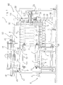
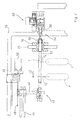
- a machine 2 for hanging products 4 comprises a product feeding line 6 which ends at a first conveying means 8, consecutive to which there is arranged a second conveying means 10; the first conveying means 8 and the second conveying means 10 are arranged transversally relative to the line 6 and the products 4 can be transported whilst they are positioned transversally on them.
- the first conveying means 8 defines a horizontal conveying surface for products 4 along the direction shown by the arrow F, while the second conveying means 10 defines an inclined conveying surface for the products 4, in such a way that a loop-shaped or eyelet-shaped portion 12 of each product 4 can engage in an intermediate rod-shaped supporting means 14, one end of which is fixed to a respective sliding block 16.
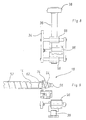
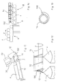
- a further end of the intermediate supporting means 14 is advantageously associated with an appendix 100 ( Figure 13), or with point means 18, capable of facilitating insertion of the loop-shaped portion 12 of each product 4 onto said intermediate supporting means.
- Rocking means 20 is supported in a rotating manner on a frame body 19 and serves as a guide for a pair of sliding blocks 16 engaged to move along the rocking means 20 by a suitable drive means 26 and a transmission means 28 comprising bow-shaped connecting rods 30.
- An intermediate portion of the rocking means 20 is engaged by a shaft 22 which is made to oscillate around its own longitudinal axis by a drive means 24 in such a way as to make the rocking means 20 perform angular movements with an amplitude of approximately 180° in one direction and in the opposite direction.
- the combined movement of the sliding blocks 16 on the rocking means 20 is such that the products 4 are raised according to a trajectory that comprises an initial substantially vertical section Z1 and a final curved section Z2. This limits the oscillations of the products 4 during transfer.
- the rod-shaped intermediate supporting means 14 if associated with the point means 18, is divested of said means 18 by the action of gripper means 32 provided with jaws 34 capable of grasping the point means 18 and moving it from the position in which it is inserted on the rod-shaped intermediate supporting means 14 to a neutral waiting position C in which the point means 18 is not engaged on the rod-shaped intermediate supporting means 14.
- the gripper means 32 is coupled with an angular positioning rod 36 hinged at one end to a pin 38 and capable of being moved in an angular direction by way of a pneumatic cylinder 40.
- the jaws 34 can be actuated by a pneumatic cylinder 35 to close and open on the external peripheral surface of the point means 18.
- the jaws 34 can be moved in a guided fashion by guide bushings 98 in a direction parallel to the axis of the intermediate supporting means 14 by way of a suitable pneumatic cylinder 96.
- the gripper means 32 is not necessary.
- the rod-shaped intermediate supporting means 14 is advantageously tubular, after its end has been freed from the point means 18, it is possible to introduce into it a rod-shaped further supporting means, or supporting means, 14a making it enter axially through the free end of the intermediate supporting means 14 in the direction shown by the arrow F1 under the action of a further gripper means 42 supported by an arm 46 on a crossbeam 44 of the frame 19 extending along direction F1.
- a belt 48 interconnected with the arm 46 and closed on end pulleys 49 to form a ring and driven by a geared motor means 50, permits alternating linear sliding of the further gripper means 42 along the crossbeam 44 so as to move the rod-shaped further supporting means 14a from an external position D, in which it is completely outside of and aligned with the intermediate supporting means 14, to an internal position E, in which the further supporting means 14a is inserted inside the intermediate tubular supporting means 14, and vice versa.
- the intermediate supporting means 14 is made to rotate around its longitudinal axis so that the products 4 are moved along the intermediate supporting means in the direction F2 opposite to direction F1.
- a sensor which is not shown, acts on the rotational drive means 60 in order to interrupt the command for rotation of the intermediate supporting means 14, and actuates a command to move the further gripper means 42 which extracts the further supporting means 14a from the intermediate supporting means 14 by an amount corresponding to the desired linear step of the products 4 on the further supporting means 14a.
- An analogous rotational drive means which is not shown, may also be provided in the row-forming station A to facilitate insertion of the loop-shaped portions 12 on the intermediate supporting means 14.
- the point means 18 has a tang 62 inserted inside the intermediate supporting means 14, and is externally provided with a helicoidal channel 64 to facilitate insertion of the loop-shaped portions 12 on the intermediate supporting means 14. Furthermore, the point means 18 is provided at its free end opposite tang 62 with an annular projection 66 capable of preventing the loop-shaped portions 12 from coming disengaged from the point means 18 in the row-forming station when they are inserted on the intermediate supporting means 14.
- the intermediate supporting means 14 is provided, at its further end, with the appendix 100 which projects laterally from the profile of the intermediate supporting means 14 with a shape that advantageously constitutes an extension of the helicoidal groove 52.
- the shape of the helicoidal shaped appendix 100 is such as not to obstruct transfer of the products 4 from the intermediate supporting means 14 to the further supporting means 14a in the transfer station B.
- the further supporting means 14a is moved to the transfer station B from a feeding means 68 comprising a pair of chains 70 wound to form a ring and driven by a drive means 69 and arranged in such a way as to support both ends of the further supporting means 14a and to make it advance towards the row-transfer station B in the direction shown by arrow F3.
- the pair of chains 70 defines a conveying surface for the further supporting means 14a arranged almost at the same height as the row-transfer station B.
- a pick-up and transfer means 72 comprising oscillating arms 74 which can be moved in an angular direction by a pneumatic cylinder 75 on a slide means 76 between a pick-up position in which it engages end zones of the further supporting means 14a from below one at a time, and a delivery position in which it leaves the further supporting means 14a available for the action of the further gripper means 42.
- the oscillating arms 74 position themselves below the further supporting means 14a and receive the products and then transfer them to the outfeed means 78 below. This occurs by way of vertical sliding of the slide means 76 along a respective upright means 80 due to the action of a belt drive 82 driven by a geared motor 83 and wound onto respective pulleys to form a ring.
- the outfeed means 78 of the further supporting means 14a with the products 4 hanging from it is positioned almost at the same height as the row-forming station A.
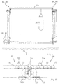
- the outfeed means 78 comprises a first pair of chains 84 and a second pair of chains 86 arranged consecutively relative to the first pair of chains 82 driven by separate drive means 88, 90 coupled respectively to the pairs of chains 84, 86 by way of respective flexible transmission units 89, 91.
- the further supporting means 14a are progressively unloaded onto the outfeed means 78 as they are picked up from row-transfer station B by the oscillating arms 74.
- the further supporting means 14a is deposited on the first pair of chains 84 and is moved in steps towards the outfeed in the direction shown by the arrow F4 until there is formed a loading layer of products 4 of a storage means, which is not shown, according to the characteristics of the production plant.
- a layer of products 4 has been formed on the first pair of chains 84, it is transferred integrally to the second pair of chains 86 where it remains waiting to be picked up by a conveying means towards the storage means, while the oscillating arms 74 can transfer the further supporting means 14a which in the meantime has become free at the row-transfer station B.
- the pairs of chains 84, 86 are provided externally with formations of teeth 92 defining spaces capable of receiving end zones of the further supporting means 14a.
Landscapes
- Life Sciences & Earth Sciences (AREA)
- Engineering & Computer Science (AREA)
- Wood Science & Technology (AREA)
- Zoology (AREA)
- Food Science & Technology (AREA)
- Specific Conveyance Elements (AREA)
- Attitude Control For Articles On Conveyors (AREA)
- Chain Conveyers (AREA)
- Intermediate Stations On Conveyors (AREA)
Claims (9)
- Stützeinrichtung (14), geeignet zur Aufnahme von schlingenförmigen Bereichen (12) von Produkten (4), die gehalten werden sollen, umfassend einen Anhang (100), der von einem Ende der Stützeinrichtung (14) hervorsteht und dazu ausgebildet ist, die Einführung jedes der schlingenförmigen Abschnitte (12) auf das Aufnahmemittel zu erleichtern, sowie schraubenförmige Rillen (52), die dazu ausgebildet sind, die schlingenförmigen Bereiche (12) aufzunehmen, dadurch gekennzeichnet, dass das eine Ende ein freies Ende der Stützeinrichtung (14) ist.
- Stützeinrichtung (14) nach Anspruch 1, bei der der Ansatz (100) die Form eines Hakens hat.
- Stützeinrichtung (14) nach Anspruch 1 oder 2, bei der der Ansatz (100) eine Form hat, die eine Verlängerung der schraubenförmigen Rillen (52) bildet.
- Stützeinrichtung gemäß irgendeinem der Ansprüche 1 bis 3, bei der die schraubenförmigen Rillen schraubenförmige Nuten (52) umfassen.
- Stützeinrichtung (14) nach Anspruch 4, bei der der Fortsatz (100) einen Bereich umfasst, der mit der Stützeinrichtung verbunden ist und parallel zu den schraubenförmigen Nuten (52) angeordnet ist.
- Stützeinrichtung (14) nach irgendeinem der vorhergehenden Ansprüche, bei der der Fortsatz (100) ein freies Ende aufweist, das von der Stützeinrichtung (14) hervorsteht.
- Stützeinrichtung (14) nach irgendeinem der vorhergehenden Ansprüche, die ferner einen stangenförmigen Körper aufweist.
- Stützeinrichtung (14) nach Anspruch 5, bei der der stangenförmige Körper ein rohrförmiger Körper ist.
- Stützeinrichtung (14) nach irgendeinem der vorhergehenden Ansprüche, bei der der Fortsatz (100) derart geformt ist, dass er eine Ausgabe der Produkte (4) von der Stützeinrichtung (14) nicht behindert.
Priority Applications (1)
| Application Number | Priority Date | Filing Date | Title |
|---|---|---|---|
| EP04015459A EP1464225A3 (de) | 1998-02-23 | 1999-02-23 | Mittel zum Aufhängen von Objekten |
Applications Claiming Priority (4)
| Application Number | Priority Date | Filing Date | Title |
|---|---|---|---|
| ITMO980037 IT1306334B1 (it) | 1998-02-23 | 1998-02-23 | Mezzi per appendere oggetti. |
| ITMO980037 | 1998-02-23 | ||
| ITMO980083 | 1998-04-14 | ||
| ITMO980083 IT1306335B1 (it) | 1998-04-14 | 1998-04-14 | Mezzi per appendere oggetti. |
Related Child Applications (1)
| Application Number | Title | Priority Date | Filing Date |
|---|---|---|---|
| EP04015459A Division EP1464225A3 (de) | 1998-02-23 | 1999-02-23 | Mittel zum Aufhängen von Objekten |
Publications (3)
| Publication Number | Publication Date |
|---|---|
| EP0941664A2 EP0941664A2 (de) | 1999-09-15 |
| EP0941664A3 EP0941664A3 (de) | 2000-11-29 |
| EP0941664B1 true EP0941664B1 (de) | 2004-07-07 |
Family
ID=26331739
Family Applications (2)
| Application Number | Title | Priority Date | Filing Date |
|---|---|---|---|
| EP19990103419 Expired - Lifetime EP0941664B1 (de) | 1998-02-23 | 1999-02-23 | Mittel zum Aufhängen von Nahrungsmitteln |
| EP04015459A Withdrawn EP1464225A3 (de) | 1998-02-23 | 1999-02-23 | Mittel zum Aufhängen von Objekten |
Family Applications After (1)
| Application Number | Title | Priority Date | Filing Date |
|---|---|---|---|
| EP04015459A Withdrawn EP1464225A3 (de) | 1998-02-23 | 1999-02-23 | Mittel zum Aufhängen von Objekten |
Country Status (3)
| Country | Link |
|---|---|
| EP (2) | EP0941664B1 (de) |
| DE (1) | DE69918477T2 (de) |
| ES (1) | ES2222628T3 (de) |
Cited By (1)
| Publication number | Priority date | Publication date | Assignee | Title |
|---|---|---|---|---|
| CN108323556A (zh) * | 2018-01-22 | 2018-07-27 | 徐士忠 | 一种肉类食品加工用悬挂装置 |
Families Citing this family (6)
| Publication number | Priority date | Publication date | Assignee | Title |
|---|---|---|---|---|
| NL1015470C2 (nl) * | 2000-06-19 | 2001-12-28 | Wal Metaalbewerking Van De | Werkwijze en inrichting voor het naar een behandelkamer brengen van stukken worst. |
| DE10046417C1 (de) * | 2000-09-18 | 2002-03-07 | Grose Waechter Thomas | Einlegevorrichtung für an Fadenschlaufen an Spießen hängende Waren |
| ITMO20030128A1 (it) * | 2003-05-06 | 2004-11-07 | Ve Ma C Societa A Responsabilita Limitata | Apparato e metodo per trasferire oggetti |
| EP2008522A1 (de) * | 2007-06-28 | 2008-12-31 | Albert Handtmann Maschinenfabrik GmbH & Co. KG | Verfahren und Vorrichtung zum Aufnehmen von Portionen mit Schlaufe |
| EP2305044B1 (de) | 2009-10-02 | 2013-02-13 | Poly-clip System GmbH & Co. KG | Handhabungssystem zum Transportieren, Entfernen oder Einfügen von stabförmigen Elementen |
| DE102015116821B4 (de) | 2015-10-04 | 2019-01-17 | Wilhelm Unger | Auf- und Abspießvorrichtung für an Hakenspießen hängenden Waren und Arbeitsverfahren der Vorrichtung |
Family Cites Families (7)
| Publication number | Priority date | Publication date | Assignee | Title |
|---|---|---|---|---|
| US1350632A (en) * | 1919-07-02 | 1920-08-24 | Hermen E Albrecht | Gambrel |
| US4004770A (en) * | 1973-04-23 | 1977-01-25 | Karass Thomas J | Hook and hook assembly using a sling of band material |
| DE3238023A1 (de) * | 1982-10-13 | 1984-04-19 | Albert Handtmann Maschinenfabrik GmbH & Co KG, 7950 Biberach | Vorrichtung zur uebergabe von wurstschleifen auf einen rauchstock |
| DK166859B1 (da) * | 1988-10-03 | 1993-07-26 | Thorsted Maskiner As | Fremgangsmaade og baereindretning saasom en stok eller skinne af snorbaarne genstande saasom poelseemner |
| DE3935746A1 (de) * | 1989-10-27 | 1991-05-02 | Guenter Kollross | Verfahren und vorrichtung zum mechanisierten aufhaengen von wuersten |
| GB9208402D0 (en) * | 1992-04-16 | 1992-06-03 | Devro Ltd | Rotatable linking and hanging device |
| IT1279360B1 (it) * | 1995-02-17 | 1997-12-09 | Tecnomec Srl | Apparecchiatura per appendere ordinatamente oggetti, in particolare insaccati, su supporti trasferibili |
-
1999
- 1999-02-23 DE DE69918477T patent/DE69918477T2/de not_active Expired - Lifetime
- 1999-02-23 EP EP19990103419 patent/EP0941664B1/de not_active Expired - Lifetime
- 1999-02-23 EP EP04015459A patent/EP1464225A3/de not_active Withdrawn
- 1999-02-23 ES ES99103419T patent/ES2222628T3/es not_active Expired - Lifetime
Cited By (1)
| Publication number | Priority date | Publication date | Assignee | Title |
|---|---|---|---|---|
| CN108323556A (zh) * | 2018-01-22 | 2018-07-27 | 徐士忠 | 一种肉类食品加工用悬挂装置 |
Also Published As
| Publication number | Publication date |
|---|---|
| DE69918477D1 (de) | 2004-08-12 |
| EP1464225A3 (de) | 2005-08-17 |
| ES2222628T3 (es) | 2005-02-01 |
| EP0941664A2 (de) | 1999-09-15 |
| EP0941664A3 (de) | 2000-11-29 |
| DE69918477T2 (de) | 2005-08-18 |
| EP1464225A2 (de) | 2004-10-06 |
Similar Documents
| Publication | Publication Date | Title |
|---|---|---|
| US8151973B2 (en) | Suspension device for linked products | |
| US7735630B2 (en) | Suspension device for linked products | |
| US5277650A (en) | Apparatus for removing the entrails from the abdominal cavity of poultry | |
| US3533495A (en) | Apparatus for handling wieners and the like | |
| US5102368A (en) | Apparatus and method for conveying sausages | |
| EP1985189B1 (de) | Einfüllen eines Lebensmittels in einen Behälter auf einem Lamellenförderband | |
| US4478024A (en) | Stack handling method and apparatus | |
| CA2447014A1 (en) | Independent conveyor system for conveying linked food products | |
| EP0941664B1 (de) | Mittel zum Aufhängen von Nahrungsmitteln | |
| US4974391A (en) | Automatic package loading system for bakery goods and the like | |
| US4648237A (en) | Stack handling method and apparatus | |
| US4392803A (en) | Stick confection extraction apparatus | |
| EP1417128B1 (de) | Vorrichtung zum wenden von objekten | |
| US7464806B2 (en) | Suspension device for linked products | |
| EP1518461A2 (de) | Vorrichtung und Verfahren zur Übertragung von Gegenständen | |
| US5772000A (en) | Hop vine transfer system | |
| US3747821A (en) | Loader mechanism for strands of linked products | |
| JP3644634B2 (ja) | ループ状ソーセージの自動移載・搬送装置 | |
| AU4887899A (en) | Method to produce printed articles by inserting at least one part-product into a main product and device to carry out the method | |
| JPH01113016A (ja) | 容器内の食品片を洗浄するための装置 | |
| ITMO980037A1 (it) | Mezzi per appendere oggetti | |
| JP2595440B2 (ja) | 自動製麺機 | |
| US4702061A (en) | Automatic basket bail opening machine | |
| ITMO980083A1 (it) | Mezzi per appendere oggetti | |
| ITMI20011674A1 (it) | Impianto per il trattamento ed il riempimento di fusti per bevande ingenere |
Legal Events
| Date | Code | Title | Description |
|---|---|---|---|
| PUAI | Public reference made under article 153(3) epc to a published international application that has entered the european phase |
Free format text: ORIGINAL CODE: 0009012 |
|
| AK | Designated contracting states |
Kind code of ref document: A2 Designated state(s): DE ES FR IT |
|
| AX | Request for extension of the european patent |
Free format text: AL;LT;LV;MK;RO;SI |
|
| PUAL | Search report despatched |
Free format text: ORIGINAL CODE: 0009013 |
|
| AK | Designated contracting states |
Kind code of ref document: A3 Designated state(s): AT BE CH CY DE DK ES FI FR GB GR IE IT LI LU MC NL PT SE |
|
| AX | Request for extension of the european patent |
Free format text: AL;LT;LV;MK;RO;SI |
|
| 17P | Request for examination filed |
Effective date: 20010523 |
|
| AKX | Designation fees paid |
Free format text: DE ES FR IT |
|
| 17Q | First examination report despatched |
Effective date: 20030107 |
|
| GRAP | Despatch of communication of intention to grant a patent |
Free format text: ORIGINAL CODE: EPIDOSNIGR1 |
|
| GRAS | Grant fee paid |
Free format text: ORIGINAL CODE: EPIDOSNIGR3 |
|
| GRAA | (expected) grant |
Free format text: ORIGINAL CODE: 0009210 |
|
| AK | Designated contracting states |
Kind code of ref document: B1 Designated state(s): DE ES FR IT |
|
| REF | Corresponds to: |
Ref document number: 69918477 Country of ref document: DE Date of ref document: 20040812 Kind code of ref document: P |
|
| REG | Reference to a national code |
Ref country code: ES Ref legal event code: FG2A Ref document number: 2222628 Country of ref document: ES Kind code of ref document: T3 |
|
| ET | Fr: translation filed | ||
| PLBE | No opposition filed within time limit |
Free format text: ORIGINAL CODE: 0009261 |
|
| STAA | Information on the status of an ep patent application or granted ep patent |
Free format text: STATUS: NO OPPOSITION FILED WITHIN TIME LIMIT |
|
| 26N | No opposition filed |
Effective date: 20050408 |
|
| PG25 | Lapsed in a contracting state [announced via postgrant information from national office to epo] |
Ref country code: IT Free format text: LAPSE BECAUSE OF NON-PAYMENT OF DUE FEES Effective date: 20080223 |
|
| PGRI | Patent reinstated in contracting state [announced from national office to epo] |
Ref country code: IT Effective date: 20110616 |
|
| PGFP | Annual fee paid to national office [announced via postgrant information from national office to epo] |
Ref country code: FR Payment date: 20120316 Year of fee payment: 14 |
|
| PGFP | Annual fee paid to national office [announced via postgrant information from national office to epo] |
Ref country code: DE Payment date: 20120123 Year of fee payment: 14 |
|
| PGFP | Annual fee paid to national office [announced via postgrant information from national office to epo] |
Ref country code: IT Payment date: 20120223 Year of fee payment: 14 |
|
| PGFP | Annual fee paid to national office [announced via postgrant information from national office to epo] |
Ref country code: ES Payment date: 20120207 Year of fee payment: 14 |
|
| REG | Reference to a national code |
Ref country code: FR Ref legal event code: ST Effective date: 20131031 |
|
| REG | Reference to a national code |
Ref country code: DE Ref legal event code: R119 Ref document number: 69918477 Country of ref document: DE Effective date: 20130903 |
|
| PG25 | Lapsed in a contracting state [announced via postgrant information from national office to epo] |
Ref country code: FR Free format text: LAPSE BECAUSE OF NON-PAYMENT OF DUE FEES Effective date: 20130228 Ref country code: DE Free format text: LAPSE BECAUSE OF NON-PAYMENT OF DUE FEES Effective date: 20130903 |
|
| REG | Reference to a national code |
Ref country code: ES Ref legal event code: FD2A Effective date: 20140408 |
|
| PG25 | Lapsed in a contracting state [announced via postgrant information from national office to epo] |
Ref country code: ES Free format text: LAPSE BECAUSE OF NON-PAYMENT OF DUE FEES Effective date: 20130224 |
|
| PG25 | Lapsed in a contracting state [announced via postgrant information from national office to epo] |
Ref country code: IT Free format text: LAPSE BECAUSE OF NON-PAYMENT OF DUE FEES Effective date: 20140223 |