EP0941707A2 - Méthode et dispositif pour contrÔler la température lors d'un traitement dentaire au laser - Google Patents
Méthode et dispositif pour contrÔler la température lors d'un traitement dentaire au laser Download PDFInfo
- Publication number
- EP0941707A2 EP0941707A2 EP99830134A EP99830134A EP0941707A2 EP 0941707 A2 EP0941707 A2 EP 0941707A2 EP 99830134 A EP99830134 A EP 99830134A EP 99830134 A EP99830134 A EP 99830134A EP 0941707 A2 EP0941707 A2 EP 0941707A2
- Authority
- EP
- European Patent Office
- Prior art keywords
- tooth
- type
- laser
- temperature
- treatment
- Prior art date
- Legal status (The legal status is an assumption and is not a legal conclusion. Google has not performed a legal analysis and makes no representation as to the accuracy of the status listed.)
- Granted
Links
- 238000000034 method Methods 0.000 title claims abstract description 35
- 238000013532 laser treatment Methods 0.000 title claims description 7
- 238000011282 treatment Methods 0.000 claims abstract description 37
- 230000001419 dependent effect Effects 0.000 claims description 5
- 241000282465 Canis Species 0.000 claims description 4
- 210000004283 incisor Anatomy 0.000 claims description 4
- 230000003287 optical effect Effects 0.000 claims description 3
- 230000007423 decrease Effects 0.000 claims 2
- 238000010586 diagram Methods 0.000 description 11
- 230000003247 decreasing effect Effects 0.000 description 3
- 210000003298 dental enamel Anatomy 0.000 description 3
- 210000004268 dentin Anatomy 0.000 description 3
- 239000000463 material Substances 0.000 description 3
- 230000000875 corresponding effect Effects 0.000 description 2
- 238000012544 monitoring process Methods 0.000 description 2
- 238000013021 overheating Methods 0.000 description 2
- 206010061218 Inflammation Diseases 0.000 description 1
- 230000004913 activation Effects 0.000 description 1
- 239000012620 biological material Substances 0.000 description 1
- 239000008280 blood Substances 0.000 description 1
- 210000004369 blood Anatomy 0.000 description 1
- 230000001276 controlling effect Effects 0.000 description 1
- 238000001816 cooling Methods 0.000 description 1
- 230000002596 correlated effect Effects 0.000 description 1
- 125000004122 cyclic group Chemical group 0.000 description 1
- 230000000694 effects Effects 0.000 description 1
- 231100001261 hazardous Toxicity 0.000 description 1
- 230000017525 heat dissipation Effects 0.000 description 1
- 230000004054 inflammatory process Effects 0.000 description 1
- 230000003993 interaction Effects 0.000 description 1
- 238000005259 measurement Methods 0.000 description 1
- 239000013307 optical fiber Substances 0.000 description 1
- 230000000630 rising effect Effects 0.000 description 1
- 239000000126 substance Substances 0.000 description 1
Images



Classifications
-
- A—HUMAN NECESSITIES
- A61—MEDICAL OR VETERINARY SCIENCE; HYGIENE
- A61B—DIAGNOSIS; SURGERY; IDENTIFICATION
- A61B18/00—Surgical instruments, devices or methods for transferring non-mechanical forms of energy to or from the body
- A61B18/18—Surgical instruments, devices or methods for transferring non-mechanical forms of energy to or from the body by applying electromagnetic radiation, e.g. microwaves
- A61B18/20—Surgical instruments, devices or methods for transferring non-mechanical forms of energy to or from the body by applying electromagnetic radiation, e.g. microwaves using laser
-
- A—HUMAN NECESSITIES
- A61—MEDICAL OR VETERINARY SCIENCE; HYGIENE
- A61C—DENTISTRY; APPARATUS OR METHODS FOR ORAL OR DENTAL HYGIENE
- A61C1/00—Dental machines for boring or cutting ; General features of dental machines or apparatus, e.g. hand-piece design
- A61C1/0046—Dental lasers
-
- A—HUMAN NECESSITIES
- A61—MEDICAL OR VETERINARY SCIENCE; HYGIENE
- A61B—DIAGNOSIS; SURGERY; IDENTIFICATION
- A61B17/00—Surgical instruments, devices or methods
- A61B2017/00017—Electrical control of surgical instruments
- A61B2017/00115—Electrical control of surgical instruments with audible or visual output
- A61B2017/00119—Electrical control of surgical instruments with audible or visual output alarm; indicating an abnormal situation
-
- A—HUMAN NECESSITIES
- A61—MEDICAL OR VETERINARY SCIENCE; HYGIENE
- A61B—DIAGNOSIS; SURGERY; IDENTIFICATION
- A61B18/00—Surgical instruments, devices or methods for transferring non-mechanical forms of energy to or from the body
- A61B2018/00636—Sensing and controlling the application of energy
Definitions
- the present invention relates to a device for laser treatment in dentistry and a control method for this treatment, capable of making the use of the device safer and easier when used on hard tissues such as enamel and dentine.
- lasers are also used to treat the hard tissues, namely enamel and dentine.
- a dentist using a laser does not have access to means for directly measuring the temperature of the tooth. This makes the use of lasers in these applications difficult and slow. This is because the dentist is obliged to apply the laser according to his judgment, in other words for sufficiently short periods and with a sufficiently long interval between one application and the next to prevent hazardous rises in the temperature of the tooth.
- the object of the present invention is to provide a laser device for the treatment of tissues, and in particular a device for orthodontic use, which can be used to overcome the prior art problems described above.
- the object of the present invention is to provide a device which enables the operator to apply the laser without the need to intervene in an empirical and uncertain way with successive interruptions to prevent the risk of overheating of the treated tissues.
- a further object of the present invention is to provide a control method for laser treatment in dentistry which enables overheating of the treated tissue to be prevented.
- Yet another object of the present invention is to provide a method capable of making the use of a laser device for orthodontic applications simpler and safer, particularly in the treatment of hard tissues such as enamel and dentine.
- the alarm situation may be indicated to the operator by means of an acoustic or optical signal or by a combination of the two, or by another suitable method. There is no reason why automatic interruption of the treatment in case of alarm should not be provided.
- the estimated temperature is also determined as a function of the emission power of the laser. It is also possible to provide for the characteristics of the tooth, such as the type of tooth (incisor, canine, molar, premolar), its size and its age, in other words the patient's age, to be considered in the determination of the estimated temperature. The way in which these variables may affect the calculation of the estimated temperature will be described with reference to an example of embodiment.
- the estimated temperature is made to be shown on a graph as a function of the treatment. The operator can thus also determine (in a qualitative way at least) the time available before the limit temperature is reached. This may be useful in some circumstances.
- the device to which the invention is applied consists, in outline (see Fig. 1), of a laser source 1 connected to a treatment set 3, for example by means of an optical fiber 5, an optical path with deflecting mirrors and beam guide tubes, or other.
- the laser source is connected to a programmable central control unit 7, with a keyboard 9 and a monitor 11.
- the laser source 1 is activated by the operator by means of a suitable control, in this example a control pedal 13. Devices of this type are known and do not require further description.
- the central unit 7 is programmable in such a way as to calculate the estimated value of the temperature of the tooth D during the laser treatment, as a function of a set of parameters of the tooth and of the patient undergoing the treatment, and of operating parameters of the device.
- the time constant ⁇ expressed in tenths of a second, is used to determine the estimated variation of the temperature inside the tooth when the tooth is struck by the laser beam for the treatment.
- the equation (1) and the values of the parameters appearing in it, by means of which the time constant ⁇ is calculated, are determined experimentally. They are therefore only provided by way of example, and may be modified to provide more precise values by a longer experimental phase of data acquisition.
- the variation of the temperature inside the tooth depends not only on the characteristics of the tooth, according to which the time constant ⁇ has been determined, but also on the operating conditions, and more particularly on the power of the laser beam, the laser beam emission time, and the initial temperature of the tooth.
- the temperature T max may be considered to depend only on the power W emitted by the laser, the effect of other parameters, such as the tooth size, being disregarded. It has been found by experimental measurement that the temperature T max can be correlated with the power W of the laser, as shown in Table I below: Power (W) (kW) T max (°C) 0 32 1 40 2 42 3 47 4 53 5 58 6 63 7 68 8 72 9 78
- the internal temperature of the tooth is determined by the thermodynamic characteristics of the tooth material, particularly the calorific capacity, and by the balance between the power supplied by the laser and the power dissipated into the environment by the heat dissipation which takes place on the walls of the tooth (in addition to the power removed by the circulation of blood around the tooth and within the tooth, when the tooth is not dead).
- the dissipation of heat into the environment in particular, depends on the size of the tooth. This factor may be disregarded as a first approximation, for the reasons which will be made clear subsequently, but it can be taken into consideration by means of an appropriate trial which can be carried out to find the correlation between the temperature of the tooth, the power of the incident laser beam, and the size of the tooth.
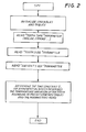
- the operator Before starting the treatment, the operator enters, through the keyboard 9, the data required by the central unit 7 for the determination of the value of the time constant ⁇ . The device then remains in the waiting state until the treatment starts.
- the central unit 7 When the laser emission is started, by activation by means of the pedal 13 after the treatment set 3 has been brought to the point where treatment is required, the central unit 7 reads the parameter "f", in other words the emission frequency, in addition to the parameter "E”, in other words the energy of the laser pulse, and from these it determines the emission power W (Equation 4).
- the central unit 7 calculates the value of T max according to Table I, which is made available to the central unit by a suitable storage system, and enables the plotting of a graph on the monitor 11, which represents the variation with time of the function (3), with the time t on the horizontal axis. Before the plotting of the graph is started, the variable T start is given the actual value (for example the base temperature of the tooth, typically assumed to be 32°C), and the emission time t is reset to zero.
- the time variable t is then gradually incremented in steps, and at each step the central unit 7 determines the estimated value T of the temperature by the equation (3).
- the estimated temperature T is compared with a threshold alarm value T alarm , set, for example, at 40°C. If the value of the estimated temperature T exceeds the value T alarm , the central unit emits an alarm signal, for example an acoustic signal, which indicates to the operator the necessity of suspending the treatment to enable the tooth to cool and to prevent the reaching of temperatures which might damage the pulp tissue.
- the central unit does not emit any alarm. In all cases, it represents the calculated temperature T in graphic form on the monitor 11 and executes the next step of the calculation, after incrementing the time variable (t).
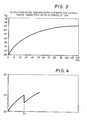
- the power of the laser is 3 W.
- the estimated temperature T is shown on the vertical axis and the time t is shown on the horizontal axis.
- the estimated temperature reaches the alarm value at approximately 26 seconds after the start of the emission. If the emission is not interrupted, the (estimated) internal temperature of the tooth increases up to an asymptotic value of approximately 47°C, which is represented by the parameter T max .
- This asymptotic value varies by approximately +/- 20% if the size of the tooth is also taken into consideration in the calculation of the estimated temperature.
- the profile of the lower region of the curve changes to a negligible extent, and therefore the time taken to reach the alarm temperature is substantially independent of the size of the tooth. For this reason, it was specified initially that the temperature T max (which represents the asymptotic value to which the curve of estimated temperature tends) does not have to allow for the size of the tooth.
- the power W falls to zero and therefore the parameter T max falls to the value of 32°C (base temperature of the tooth).
- equation (3) shows that the temperature T has an exponential variation decreasing asymptotically to the value of 32°C. This variation continues until the next start of the laser emission.
- the central unit 7 then proceeds (with the new values assigned to the parameters T max and T start ) to determine the variation of the temperature with time (decreasing) and to represent this variation on the graph on the monitor 11.
- the movement along the time axis is interrupted for the whole of the time in which the laser emission is equal to zero and the curve representing the estimated temperature T is decreasing. In this way, it is possible to reduce the size of the monitor, or to represent the variation of the temperature T on the monitor for a longer time interval.
- the graph on the monitor therefore shows a straight line parallel to the vertical axis, as shown in Fig. 4, where it is assumed that the laser emission is interrupted at the time t 1 .
- the central unit 7 When the operator considers that the value of the temperature T has fallen sufficiently below the alarm value T alarm , or in any case when the treatment is recommenced, the central unit 7 will again start to detect an exponential increase of the estimated temperature from the value T reached at the instant of starting the second stage of emission.
- the form of the curve representing T will be rising again, since the parameter T start will take the last estimated value of T at the end of the cooling stage in the absence of emission, and the parameter T max will take the value (Table I) corresponding to the emission power, which will now be different from zero.
- the procedure described above is summarized in the general flow chart in Fig. 5 and in the detailed flow charts in Figs. 6 and 7.
- the number 101 indicates the block representing the initialization stage, represented in detail in the diagram in Fig. 2 and described previously.
- the central unit 7 makes cyclic checks to see whether the state of the laser emission controller has been changed, in other words (if the emission has not yet been started) if the laser is still in the non-emitting condition (block 103). If the last monitoring cycle does not find that the laser controller 13 has been activated, the central unit checks whether the plotting of the temperature graph has been enabled (block 106). If the outcome is negative (in other words, if the intervention has not yet been started) the system returns to block 103 and recommences the monitoring cycle.
- the checking process moves to block 107 which checks whether more than one second has elapsed since the preceding check. If the outcome is negative, it returns to block 103; if positive, it proceeds to plot the graph (block 108) to show the estimate of the temperature T for the next step, the graph being plotted in steps of 1 second.
- block 104 If it is found in block 104 that the controller 13 has been activated, this means that the laser has been started or stopped, and that the values of the parameters for the calculation of the estimated temperature T must therefore be changed. If the laser has been started for the first time, the calculation of the function T must be commenced; if the laser has been stopped or restarted after a first stop, the values of the parameters T start and T max must be changed, as described above.
- the parameter E energy of the pulse
- the frequency parameter "f" is read and the emission power W is calculated (blocks 112, 113) and the value T max is determined from the power W (block 114).
- the plotting of the graph on the monitor 11 is then enabled (block 115) and the value of the present temperature (for example 32°C, in other words the base temperature of the tooth) is assigned to the variable T start , while the time variable t is reset to zero (block 116).
- the system then returns to the diagram in Fig. 5, at block 106.
- the central unit finds an interruption of the laser emission instead of a start of the laser emission in block 110, it assigns the last calculated value of the temperature T, in other words the actual temperature, to the variable T start .
- the central unit also assigns the initial value, in other words the value corresponding to a zero emission power, to the variable T max , and resets the time variable t to zero (block 117).
- the control process then returns to the diagram in Fig. 5, at block 106.
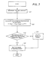
- Fig. 7 shows in detail the procedure for plotting the temperature graph (block 108).
- the time variable (t) is incremented (block 121).
- the temperature T is then estimated (block 122) and the estimated value is compared with the value of T alarm (block 123). If the alarm threshold is not exceeded (T ⁇ T alarm ) the central unit shows the newly calculated value of T on the graph displayed on the monitor 11 (block 125) and returns to block 103 (Fig. 5). If the check at block 123 reveals that the estimated temperature T is equal to or greater than the alarm value (T ⁇ T alarm ), the system emits an alarm (block 126) and then follows the previously described procedure, passing in all cases to block 125 and from there to block 103 in Fig. 5.
Landscapes
- Health & Medical Sciences (AREA)
- Physics & Mathematics (AREA)
- Life Sciences & Earth Sciences (AREA)
- Animal Behavior & Ethology (AREA)
- Optics & Photonics (AREA)
- Veterinary Medicine (AREA)
- Public Health (AREA)
- Surgery (AREA)
- General Health & Medical Sciences (AREA)
- Otolaryngology (AREA)
- Heart & Thoracic Surgery (AREA)
- Medical Informatics (AREA)
- Molecular Biology (AREA)
- Biomedical Technology (AREA)
- Engineering & Computer Science (AREA)
- Nuclear Medicine, Radiotherapy & Molecular Imaging (AREA)
- Electromagnetism (AREA)
- Oral & Maxillofacial Surgery (AREA)
- Dentistry (AREA)
- Epidemiology (AREA)
- Dental Tools And Instruments Or Auxiliary Dental Instruments (AREA)
- Laser Surgery Devices (AREA)
Applications Claiming Priority (2)
| Application Number | Priority Date | Filing Date | Title |
|---|---|---|---|
| IT98FI000059A ITFI980059A1 (it) | 1998-03-13 | 1998-03-13 | Metodo e dispositivo per il controllo della temperatura nel trattamento laser in odontoiatria |
| ITFI980059 | 1998-03-13 |
Publications (3)
| Publication Number | Publication Date |
|---|---|
| EP0941707A2 true EP0941707A2 (fr) | 1999-09-15 |
| EP0941707A3 EP0941707A3 (fr) | 2002-07-31 |
| EP0941707B1 EP0941707B1 (fr) | 2005-05-04 |
Family
ID=11352440
Family Applications (1)
| Application Number | Title | Priority Date | Filing Date |
|---|---|---|---|
| EP99830134A Expired - Lifetime EP0941707B1 (fr) | 1998-03-13 | 1999-03-12 | Méthode et dispositif pour contrôler la température lors d'un traitement dentaire au laser |
Country Status (4)
| Country | Link |
|---|---|
| EP (1) | EP0941707B1 (fr) |
| AT (1) | ATE294541T1 (fr) |
| DE (1) | DE69925060T2 (fr) |
| IT (1) | ITFI980059A1 (fr) |
Cited By (1)
| Publication number | Priority date | Publication date | Assignee | Title |
|---|---|---|---|---|
| EP1591076A2 (fr) | 2004-04-28 | 2005-11-02 | W & H Dentalwerk Bürmoos GmbH | Dispositif laser de traitement dentaire |
Families Citing this family (1)
| Publication number | Priority date | Publication date | Assignee | Title |
|---|---|---|---|---|
| CA3011873A1 (fr) * | 2018-02-19 | 2019-08-19 | Millennium Healthcare Technologies, Inc. | Appareil de laser dentaire, systeme et methode |
Family Cites Families (3)
| Publication number | Priority date | Publication date | Assignee | Title |
|---|---|---|---|---|
| US5735846A (en) * | 1994-06-27 | 1998-04-07 | Ep Technologies, Inc. | Systems and methods for ablating body tissue using predicted maximum tissue temperature |
| US5662643A (en) * | 1994-09-28 | 1997-09-02 | Abiomed R & D, Inc. | Laser welding system |
| JPH1033548A (ja) * | 1996-07-29 | 1998-02-10 | Matsushita Electric Ind Co Ltd | レーザ手術装置 |
-
1998
- 1998-03-13 IT IT98FI000059A patent/ITFI980059A1/it unknown
-
1999
- 1999-03-12 AT AT99830134T patent/ATE294541T1/de not_active IP Right Cessation
- 1999-03-12 EP EP99830134A patent/EP0941707B1/fr not_active Expired - Lifetime
- 1999-03-12 DE DE69925060T patent/DE69925060T2/de not_active Expired - Lifetime
Non-Patent Citations (1)
| Title |
|---|
| None |
Cited By (2)
| Publication number | Priority date | Publication date | Assignee | Title |
|---|---|---|---|---|
| EP1591076A2 (fr) | 2004-04-28 | 2005-11-02 | W & H Dentalwerk Bürmoos GmbH | Dispositif laser de traitement dentaire |
| US7931645B2 (en) | 2004-04-28 | 2011-04-26 | W&H Dentalwerk Bürmoos GmbH | Dental laser treatment device |
Also Published As
| Publication number | Publication date |
|---|---|
| DE69925060D1 (de) | 2005-06-09 |
| EP0941707B1 (fr) | 2005-05-04 |
| EP0941707A3 (fr) | 2002-07-31 |
| ITFI980059A0 (it) | 1998-03-13 |
| ATE294541T1 (de) | 2005-05-15 |
| DE69925060T2 (de) | 2005-09-22 |
| ITFI980059A1 (it) | 1999-09-13 |
Similar Documents
| Publication | Publication Date | Title |
|---|---|---|
| CN103403982B (zh) | 用于具有高密集前子脉冲的医疗激光器的斜升脉冲功率的启始序列 | |
| US20210069756A1 (en) | Laser system and method for operating the laser system | |
| KR102566861B1 (ko) | 레이저를 이용한 예방적 치아 경조직 치료 시스템 | |
| EP3708111B1 (fr) | Procédé et dispositif pour le nettoyage d'un canal | |
| US20100167226A1 (en) | System and method for dental applications without optical connectors in console, and handpiece assembly therefor | |
| JP6645736B2 (ja) | 多機能治療レーザによる温度制御された複合レーザ治療方法及び装置 | |
| US5330517A (en) | Device for treating tissue by pulse sequence group | |
| US5820627A (en) | Real-time optical feedback control of laser lithotripsy | |
| EP0830851B1 (fr) | Dispositif endodontique à fibre optique | |
| JPH06254104A (ja) | 歯科処置方法及び装置 | |
| Sarp et al. | Ceramic bracket debonding with ytterbium fiber laser | |
| KR20260003668A (ko) | 고효율 경조직 및 연조직 삭마 디바이스 및 방법 | |
| CN111343943A (zh) | 用于清洁通道的方法和布置 | |
| EP0941707B1 (fr) | Méthode et dispositif pour contrôler la température lors d'un traitement dentaire au laser | |
| Fahlstedt et al. | Dental implant surface temperatures following double wavelength (2780/940 nm) laser irradiation in vitro | |
| Franzen et al. | Intrapulpal temperature changes during root surface irradiation with dual-wavelength laser (2780 and 940 nm): in vitro study | |
| CN113545843B (zh) | 激光消融系统和方法 | |
| US20260022973A1 (en) | Systems for real-time laser power monitoring | |
| Yang | Optimising laser lithotripsy | |
| Hibst et al. | Measurement and modeling of temperature distribution for Er: YAG laser root canal sterilization | |
| Dostalova et al. | Laser radiation propagation in the hard and soft dental tissues | |
| JPH0299077A (ja) | レーザ光照射装置 | |
| JP2000060869A (ja) | レーザ装置 |
Legal Events
| Date | Code | Title | Description |
|---|---|---|---|
| PUAI | Public reference made under article 153(3) epc to a published international application that has entered the european phase |
Free format text: ORIGINAL CODE: 0009012 |
|
| AK | Designated contracting states |
Kind code of ref document: A2 Designated state(s): AT BE CH CY DE DK ES FI FR GB GR IE IT LI LU MC NL PT SE |
|
| AX | Request for extension of the european patent |
Free format text: AL;LT;LV;MK;RO;SI |
|
| PUAL | Search report despatched |
Free format text: ORIGINAL CODE: 0009013 |
|
| RIC1 | Information provided on ipc code assigned before grant |
Free format text: 7A 61C 1/00 A, 7A 61B 18/20 B |
|
| AK | Designated contracting states |
Kind code of ref document: A3 Designated state(s): AT BE CH CY DE DK ES FI FR GB GR IE IT LI LU MC NL PT SE |
|
| AX | Request for extension of the european patent |
Free format text: AL;LT;LV;MK;RO;SI |
|
| 17P | Request for examination filed |
Effective date: 20021127 |
|
| AKX | Designation fees paid |
Designated state(s): AT BE CH DE DK ES FI FR GB GR IE IT LI LU MC NL PT SE |
|
| GRAP | Despatch of communication of intention to grant a patent |
Free format text: ORIGINAL CODE: EPIDOSNIGR1 |
|
| GRAS | Grant fee paid |
Free format text: ORIGINAL CODE: EPIDOSNIGR3 |
|
| GRAA | (expected) grant |
Free format text: ORIGINAL CODE: 0009210 |
|
| AK | Designated contracting states |
Kind code of ref document: B1 Designated state(s): AT BE CH DE DK ES FI FR GB GR IE IT LI LU MC NL PT SE |
|
| PG25 | Lapsed in a contracting state [announced via postgrant information from national office to epo] |
Ref country code: NL Free format text: LAPSE BECAUSE OF FAILURE TO SUBMIT A TRANSLATION OF THE DESCRIPTION OR TO PAY THE FEE WITHIN THE PRESCRIBED TIME-LIMIT Effective date: 20050504 Ref country code: LI Free format text: LAPSE BECAUSE OF FAILURE TO SUBMIT A TRANSLATION OF THE DESCRIPTION OR TO PAY THE FEE WITHIN THE PRESCRIBED TIME-LIMIT Effective date: 20050504 Ref country code: IT Free format text: LAPSE BECAUSE OF FAILURE TO SUBMIT A TRANSLATION OF THE DESCRIPTION OR TO PAY THE FEE WITHIN THE PRESCRIBED TIME-LIMIT;WARNING: LAPSES OF ITALIAN PATENTS WITH EFFECTIVE DATE BEFORE 2007 MAY HAVE OCCURRED AT ANY TIME BEFORE 2007. THE CORRECT EFFECTIVE DATE MAY BE DIFFERENT FROM THE ONE RECORDED. Effective date: 20050504 Ref country code: FI Free format text: LAPSE BECAUSE OF FAILURE TO SUBMIT A TRANSLATION OF THE DESCRIPTION OR TO PAY THE FEE WITHIN THE PRESCRIBED TIME-LIMIT Effective date: 20050504 Ref country code: CH Free format text: LAPSE BECAUSE OF FAILURE TO SUBMIT A TRANSLATION OF THE DESCRIPTION OR TO PAY THE FEE WITHIN THE PRESCRIBED TIME-LIMIT Effective date: 20050504 Ref country code: BE Free format text: LAPSE BECAUSE OF FAILURE TO SUBMIT A TRANSLATION OF THE DESCRIPTION OR TO PAY THE FEE WITHIN THE PRESCRIBED TIME-LIMIT Effective date: 20050504 Ref country code: AT Free format text: LAPSE BECAUSE OF FAILURE TO SUBMIT A TRANSLATION OF THE DESCRIPTION OR TO PAY THE FEE WITHIN THE PRESCRIBED TIME-LIMIT Effective date: 20050504 |
|
| REG | Reference to a national code |
Ref country code: GB Ref legal event code: FG4D |
|
| REG | Reference to a national code |
Ref country code: CH Ref legal event code: EP |
|
| REG | Reference to a national code |
Ref country code: IE Ref legal event code: FG4D |
|
| REF | Corresponds to: |
Ref document number: 69925060 Country of ref document: DE Date of ref document: 20050609 Kind code of ref document: P |
|
| PG25 | Lapsed in a contracting state [announced via postgrant information from national office to epo] |
Ref country code: SE Free format text: LAPSE BECAUSE OF FAILURE TO SUBMIT A TRANSLATION OF THE DESCRIPTION OR TO PAY THE FEE WITHIN THE PRESCRIBED TIME-LIMIT Effective date: 20050804 Ref country code: GR Free format text: LAPSE BECAUSE OF FAILURE TO SUBMIT A TRANSLATION OF THE DESCRIPTION OR TO PAY THE FEE WITHIN THE PRESCRIBED TIME-LIMIT Effective date: 20050804 Ref country code: DK Free format text: LAPSE BECAUSE OF FAILURE TO SUBMIT A TRANSLATION OF THE DESCRIPTION OR TO PAY THE FEE WITHIN THE PRESCRIBED TIME-LIMIT Effective date: 20050804 |
|
| PG25 | Lapsed in a contracting state [announced via postgrant information from national office to epo] |
Ref country code: PT Free format text: LAPSE BECAUSE OF FAILURE TO SUBMIT A TRANSLATION OF THE DESCRIPTION OR TO PAY THE FEE WITHIN THE PRESCRIBED TIME-LIMIT Effective date: 20051017 |
|
| NLV1 | Nl: lapsed or annulled due to failure to fulfill the requirements of art. 29p and 29m of the patents act | ||
| REG | Reference to a national code |
Ref country code: CH Ref legal event code: PL |
|
| PLBE | No opposition filed within time limit |
Free format text: ORIGINAL CODE: 0009261 |
|
| STAA | Information on the status of an ep patent application or granted ep patent |
Free format text: STATUS: NO OPPOSITION FILED WITHIN TIME LIMIT |
|
| PG25 | Lapsed in a contracting state [announced via postgrant information from national office to epo] |
Ref country code: GB Free format text: LAPSE BECAUSE OF NON-PAYMENT OF DUE FEES Effective date: 20060312 |
|
| PG25 | Lapsed in a contracting state [announced via postgrant information from national office to epo] |
Ref country code: IE Free format text: LAPSE BECAUSE OF NON-PAYMENT OF DUE FEES Effective date: 20060313 |
|
| ET | Fr: translation filed | ||
| PG25 | Lapsed in a contracting state [announced via postgrant information from national office to epo] |
Ref country code: MC Free format text: LAPSE BECAUSE OF NON-PAYMENT OF DUE FEES Effective date: 20060331 Ref country code: LU Free format text: LAPSE BECAUSE OF NON-PAYMENT OF DUE FEES Effective date: 20060331 |
|
| 26N | No opposition filed |
Effective date: 20060207 |
|
| GBPC | Gb: european patent ceased through non-payment of renewal fee |
Effective date: 20060312 |
|
| REG | Reference to a national code |
Ref country code: IE Ref legal event code: MM4A |
|
| PG25 | Lapsed in a contracting state [announced via postgrant information from national office to epo] |
Ref country code: ES Free format text: LAPSE BECAUSE OF NON-PAYMENT OF DUE FEES Effective date: 20060331 |
|
| PGFP | Annual fee paid to national office [announced via postgrant information from national office to epo] |
Ref country code: FR Payment date: 20140227 Year of fee payment: 16 |
|
| PGFP | Annual fee paid to national office [announced via postgrant information from national office to epo] |
Ref country code: DE Payment date: 20140415 Year of fee payment: 16 |
|
| REG | Reference to a national code |
Ref country code: DE Ref legal event code: R119 Ref document number: 69925060 Country of ref document: DE |
|
| REG | Reference to a national code |
Ref country code: FR Ref legal event code: ST Effective date: 20151130 |
|
| PG25 | Lapsed in a contracting state [announced via postgrant information from national office to epo] |
Ref country code: DE Free format text: LAPSE BECAUSE OF NON-PAYMENT OF DUE FEES Effective date: 20151001 |
|
| PG25 | Lapsed in a contracting state [announced via postgrant information from national office to epo] |
Ref country code: FR Free format text: LAPSE BECAUSE OF NON-PAYMENT OF DUE FEES Effective date: 20150331 |