EP0941771A2 - Segment de mur pour la construction d'une cabine - Google Patents
Segment de mur pour la construction d'une cabine Download PDFInfo
- Publication number
- EP0941771A2 EP0941771A2 EP99104505A EP99104505A EP0941771A2 EP 0941771 A2 EP0941771 A2 EP 0941771A2 EP 99104505 A EP99104505 A EP 99104505A EP 99104505 A EP99104505 A EP 99104505A EP 0941771 A2 EP0941771 A2 EP 0941771A2
- Authority
- EP
- European Patent Office
- Prior art keywords
- infill
- frame
- mounting frame
- wall segment
- segment according
- Prior art date
- Legal status (The legal status is an assumption and is not a legal conclusion. Google has not performed a legal analysis and makes no representation as to the accuracy of the status listed.)
- Withdrawn
Links
Images


Classifications
-
- B—PERFORMING OPERATIONS; TRANSPORTING
- B05—SPRAYING OR ATOMISING IN GENERAL; APPLYING FLUENT MATERIALS TO SURFACES, IN GENERAL
- B05B—SPRAYING APPARATUS; ATOMISING APPARATUS; NOZZLES
- B05B16/00—Spray booths
- B05B16/40—Construction elements specially adapted therefor, e.g. floors, walls or ceilings
-
- B—PERFORMING OPERATIONS; TRANSPORTING
- B05—SPRAYING OR ATOMISING IN GENERAL; APPLYING FLUENT MATERIALS TO SURFACES, IN GENERAL
- B05B—SPRAYING APPARATUS; ATOMISING APPARATUS; NOZZLES
- B05B13/00—Machines or plants for applying liquids or other fluent materials to surfaces of objects or other work by spraying, not covered by groups B05B1/00 - B05B11/00
- B05B13/02—Means for supporting work; Arrangement or mounting of spray heads; Adaptation or arrangement of means for feeding work
- B05B13/04—Means for supporting work; Arrangement or mounting of spray heads; Adaptation or arrangement of means for feeding work the spray heads being moved during spraying operation
- B05B13/0447—Installation or apparatus for applying liquid or other fluent material to conveyed separate articles
- B05B13/0452—Installation or apparatus for applying liquid or other fluent material to conveyed separate articles the objects being vehicle components, e.g. vehicle bodies
Definitions
- the present invention relates to a wall segment for a Cabin construction, in particular for a painting installation, comprising a infill frame and one assembled in one Condition of the infill held on the infill frame, which comprises a infill element.
- the respective Infill element When assembling the known wall segments, the respective Infill element directly in the infill frame glued in. In the case of these wall segments, it comprises the one on the infill frame infill held only that Infill element.
- the present invention is therefore based on the object a wall segment of the type mentioned at the beginning create a replacement of the infill faster can take place and with a lower risk of injury connected is.
- the infill comprises a mounting frame that connected to the infill element and in the assembled Condition is releasably held on the infill frame.
- the concept of the invention has the advantage that infill element connected to the mounting frame in simple Way be removed from the infill frame can, since the infill element is not directly on the infill frame is glued, but by means of the mounting frame is releasably held on the infill frame. Thereby there is no need to remove adhesive residues on the infill frame what the substitution reduces the time required and the risk of injury when changing the infill elements.
- the removal and reinstallation of infill elements on wall segments of a cabin construction in operation can therefore with a much lower and precisely calculated time expenditure in advance become.
- the downtime of the Cabin construction can last for the duration of removal and installation of the mounting frame can be shortened, which is significantly lower is a direct than the usual curing times Adhesive connection between the infill element and the Infill frame.
- the mounting frame molded onto the infill element or in one piece with the infill element is formed.
- a one-piece design of the mounting frame with the infill element is particularly useful in cases where which the infill element consists of a material that in the manufacture of the infill or a suitable one Post processing into a complex geometric Can be shaped, such as a metal, especially steel or aluminum, or a plastic.
- the mounting frame and Infill element two separately manufactured Elements are used to form the infill with each other get connected.
- the mounting frame and the infill element can from the same material or from different ones Materials are made.
- connection of the mounting frame with the infill element preferably takes place in that the infill element is glued to the mounting frame.
- the infill element Since the infill element is glued to the mounting frame even before the infill is installed in the infill frame separately from the infill framework the replacement required for the infill Downtime of the cabin construction by the for the Hardening of the adhesive connection between the infill element and does not extend the time required for the mounting frame, since the curing of this adhesive connection is already in advance of the service activities outside the cabin construction he follows.
- the curing-related interim storage time is also eliminated outside the cabin construction and will also simplify the gluing of the infill element achieved on the mounting frame.
- the mounting frame by means of a clamp connection held on the infill frame is.
- the infill frame comprises a frame element and a clamping profile, between which the mounting frame is clamped in the assembled state is.
- the clamping profile has a T-slot.
- the mounting frame preferably comprises a connection area, with the mounting frame in the assembled state the infill frame is held, and a receiving area, on which the infill element is held.
- connection area of the mounting frame has a thickness that in essentially the expansion of one on the infill frame the intended receptacle corresponds to the connection area the mounting frame engages in the assembled state, so this allows different infills with different trained infill elements and different trained mounting areas of the mounting frame to be releasably arranged on the same infill frame.
- the infill and the Infill frame of the wall segment according to the invention their facing the interior of the cabin construction Front are flush with each other.
- the receiving area of the mounting frame preferably one less thickness than the connection area.
- the recording area is comparatively thin infill elements preferably a greater thickness on as the connection area.
- the thickness of the infill element, the receiving area preferably has the same Thickness like the connection area.
- the recording area of the mounting frame advantageously such a thickness on that a front of the infill element in the assembled Condition flush with one adjacent to it Is the front of the infill frame.
- Sealing the interior of the cabin structure compared to the outside space is made possible in that assembled state, preferably from a sealant after installing the infill on the infill frame formed, sealing element between the infill element and the infill frame is arranged.
- the sealant does not have any additional function a mass can be used come that has a good sealing effect without after a Expansion of the infill to remove residues that are difficult to remove to leave the infill frame.
- the separating film is an elastic element includes. In this way, a balance of dimensions, shape and Positional tolerances of the components used on the clamping the infill can be achieved.
- the elastic element is a particularly favorable one-sided adhesive tape includes. This can create a flush Assembly of the elastic element on the infill frame be relieved.
- a simple and inexpensive manufacture of the mounting frame is achieved when the mounting frame, preferably mitred, mounting frame profiles included.
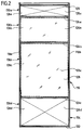
- Fig. 1 One shown in detail in Fig. 1, as a whole with 100 designated cabin construction of a paint shop has self-supporting cabin walls 102 which are made up of individual composed essentially of tabular wall segments 104 are, which are from a cabin floor 106 to extend to a cabin ceiling 108.
- the cabin floor 106 is formed by a grid, below which is the usual circulation and cleaning equipment in spray booths are located.
- the cabin ceiling 108 is composed of individual, essentially panel-shaped ceiling elements 112 assembled together form a filter mat arrangement, which in turn forms a floor of the so-called plenum 114, which is arranged above the spray booth.
- each includes tabular wall segments 104 a circumferential, closed, rectangular profile frame 116, which in the assembled state vertically running side profiles 118a and 118b as well an upper one running horizontally when assembled Cross profile 120 and one horizontally when assembled extending lower cross profile 122.
- the profile frame 116 of the wall segment 104 is by others Intermediate cross sections 124a, 124b and 124c, which are between the upper cross section 120 and the lower cross section 122 in in the assembled state horizontal direction from one Extend side profile 118a to the other side profile 118b, divided into individual compartments 126a, 126b, 126c and 126d, in which to be described in more detail one infill 128 is detachably held.
- the upper cross section 120 forms the uppermost intermediate cross section 124a and that between the upper cross section 120 and the uppermost intermediate cross section 124a Portions of the side profiles 118a and 118b together form one Infill frame 130a for infill 128a of the compartment 126a.
- the top intermediate cross section 124a, the middle intermediate cross section 124b and those lying between these profiles Form sections of the side profiles 118a and 118b together a infill frame 130b for the infill 128b of compartment 126b.
- the middle intermediate cross section 124b, the lowest intermediate cross section 124c and those lying between these profiles Form sections of the side profiles 118a and 118b together a infill frame 130c for the infill 128c of compartment 126c.
- each of the infills 128 includes one infill element having the shape of a rectangular plate 132 and one along the edges of the infill element 132 arranged rectangular mounting frame 134, consisting of four miter-cut mounting frame profiles 136 is composed.
- Inner side 150 of inner region 140 runs underneath at an acute angle to the front face 148 of the interior 140, so that the inner region 140 of the mounting frame profile 136 from the front 148 to the back 144 tapered.
- the outer areas 138 of the four mounting frame profiles 136 together form a connection area 152 of the mounting frame 134.
- the interior areas 140 of the four mounting frame profiles 136 together form a receiving area 154 of the mounting frame 134.
- the infill 132 On the front 148 of the inner areas 140 of the Mounting frame profiles 136 formed front 156 of the Receiving area 154 of the mounting frame 134 is one Back 158 of the infill 132, which for example made of glass, plastic, metal, in particular Stainless steel or aluminum, or a composite material can and in the case of infill 128c consists of glass.
- the infill element 132 and the receiving area 154 of the Mounting frame 134 are interposed pasty, as a thin film on the receiving area 154 of the Mounting frame 134 applied adhesive layer 160 permanently elastic connected with each other.
- a double-sided adhesive can also be used Contact adhesive tape for connecting the infill element 132 with the receiving area 154 of the mounting frame 134 is provided be.
- the Ausfachungselements 132 on the mounting frame 134 to Curing of the pasty adhesive layer required intermediate storage time; furthermore the gluing of the infill element 132 simplified on the mounting frame 134 and the Handling of the infill 132 and the mounting frame 134 comprehensive adhesive group, d. H. the infill 128, simplified.
- the infill element 132 has a height and a width that are slightly less than the height or width of the receiving area 154 of the mounting frame 134, so that between upper, lower and side outer surfaces 162 the infill 132 on the one hand and over the front 156 of the receiving area 154 protruding inner sides 164 of the connection area 152 of the mounting frame 134 on the other hand a gap 165 remains.
- the infill 128 When assembled, the infill 128 is four-sided releasably on the respectively assigned infill frame 130 held.
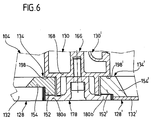
- FIG. 1 a cross section is shown in FIG the junction between a infill 128 and one a component of the infill 128 Folding frame 130 forming frame element 166 shown, which is in the assembled state along an edge the infill 128 extends.
- the frame element 166 a front wall 168, of the front 170 two spaced apart, each in the longitudinal direction of the Frame element 166 extending clamping profile channel side walls Project 172a and 172b forward.
- the side walls 172a and 172b form one between them Clamping profile channel 174, in the assembled state Holding area 176 in the longitudinal direction of the frame element 166 extending clamping profile 178, which has a substantially rectangular cross section and on which on both sides of the longitudinal axis of the clamping profile 178 in each case one overlapping one of the side walls 172a, 172b Terminal strip 180a, 180b of the clamping profile 178 is formed.
- each terminal block 180a, 180b each have a shoulder 181a, 181b on which the respectively assigned side wall 172a, 172b in the assembled Condition is present.
- the holding area 176 of the clamping profile 178 At its front is the holding area 176 of the clamping profile 178 with a parallel to the longitudinal axis of the clamping profile 178 extending groove 182 provided in the holding area 176 through holes penetrating from the rear 184 flow out.
- the through holes 184 are each by a fastening screw 188 interspersed, the one with an external thread provided shaft 190 in one of the threaded blind holes 186 is screwed in and its screw head 192 on the bottom of the Groove 182 abuts so that the clamping profile 178 between the Screw head 192 and the front 170 of the front wall 168 of the frame element 166 is clamped.
- the groove 182 is towards the front of the clamping profile 178 by means of a clip profile 194 which is snapped into the same, which extends parallel to the longitudinal direction of the groove 182 and on its front with the front of the Terminal strips 180a and 180b of the clamping profile 178 is flush, locked.
- connection area 152 of the mounting frame 134 lies above an interposed release film 204 on the back the terminal block 180a so that the connection area 152 of the mounting frame 134 between the front wall 168 of the frame element 166 on the one hand and the terminal strip 180a of the clamping profile 178 is clamped on the other hand.
- the gap 165 is between the infill 132 on the one hand and the mounting frame 134 and the clamping profile 178 on the other hand with one filled with a sealing compound 208, the sealing of the to the front of the infill element 132 adjacent interior of the cabin construction serves against the outside space of the same.
- connection area 152 of the mounting frame 134 and the terminal strip 180a arranged separating film 204 is prevented that the filler in the joint between the connection area 152 and the terminal block 180a creeps and after it has hardened to a stick of the mounting frame 134 with the clamping profile 178.
- the separating film 204 are formed by an elastic band.
- the elastic Tape be designed adhesive on one side.
- the infill element 132 is made using a Glue or a double-sided tape on the recording area 154 of the mounting frame 134 glued on.
- the infill 128 is then in the associated infill frame 130 arranged that the back 200 of the Connection area 152 of the mounting frame 134 on the contact surfaces 198 of the frame elements 166 of the infill frame 130 is present.
- clamping profiles 178 are attached to the respective one Frame element 166 arranged that the terminal strips 180a via the separating film 204 at the connection area 152 of the mounting frame 134 and the back of the holding areas 176 on the front sides 170 of the front walls 168 of the respective Frame elements 166 abut, and the clamping profiles 178 are in this position using the mounting screws 188, which are screwed into the threaded blind holes 186, secured.
- gap 165 is filled with filler, to form the sealing element 208.
- the infill is 128 fully assembled in the infill frame 130.
- a frame element 166 Be part of several infill frames 130, 130 '.
- Terminal strip 180b the connection area 152 'of the mounting frame 134 'of a second infill 128' is.
- the first infill 128 corresponds in terms of its structure and their dimensions of those already related above with the infill described in Figures 4 and 5 128 and includes a glass infill 132.
- the recording area 154 'of the mounting frame 134' of the second infill 128 ', to which the infill element 132 'is glued one correspondingly greater thickness than the receiving area 154 of the Mounting frame 134 of the first infill 128 so that the sum of the thicknesses of the receiving area 134 'and the infill element 132 'of the second infill 128' of the sum the thicknesses of the receiving area 154 and the infill element 132 corresponds to the first infill 128.
- connection area 152 'of the mounting frame 134' of second infill 128 ' has the same thickness as the connection area 152 of the mounting frame 134 of the first infill 128 to free play between the contact surface 198 'and the clamping bar 180b are clamped which have the same distance from each other as the contact surface 198 and the terminal block 180a.
- the receiving area 154 'of the mounting frame 134' of the second infill 128 ' a greater thickness than the connection area 152 '; of the Recording area 154 'is thus opposite the connection area 152 'to the front of the infill 128' over.
- the receiving area 154 and the connection portion 152 of the mounting frame 134 one Infill 128 have essentially the same thickness, namely when the thickness of the infill 132 in essentially the sum of the thicknesses of a terminal strip 180a, 180b and the separating film 204 arranged thereon.
- a second embodiment of a shown in FIG Wall segments 104 for a cabin construction 100 differs from the embodiment described above in that the mounting frame profiles 136 of the mounting frame 134, 134 'of the infills 128, 128' used not massive, as in the first embodiment, but are hollow.
- the mounting frames 134, 134 ' must have sufficient strength to withstand the the infill elements 132, 132 'mechanical To withstand loads.
- the second embodiment of a wall segment is correct 104 for a cabin construction 100 regarding Structure and function with the first described above Embodiment match, reference to the description becomes.
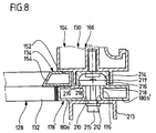
- a third embodiment of a shown in FIG Wall segments 104 for a cabin construction 100 differs different from the embodiments described above with regard to the formation of the clamping profile.
- the stop section 214 has a larger width on as the insertion portion 212 so that the stop portion 214 the crossbar of the substantially T-shaped Cross section of the T-groove 210 forms.
- the T-slot 210 makes it easy and time-saving Way an accessory shown schematically in Fig. 8 213 on the front of the clamping profile 178 '.
- T-nut 217 is substantially in the shape of a elongated cuboids on, two diagonally Opposite rectangular edges are chamfered to stop surfaces to form the T-nut.
- To go through the insertion section 212 to fit the T-slot 210 becomes the T-slot nut 217 inserted into the T-slot 210 so that its longitudinal axis coincides with the longitudinal axis of the T-slot 210.
- the clamping strips 180a 'and 180b' of the clamping profile 178 ' have a greater thickness than the terminal strips 180a or 180b of the clamping profile 178 of the first two embodiments.
- the terminal strips 180a 'and 180b' are hollow educated.
- the third embodiment of a wall segment is correct 104 for a cabin construction 100 regarding Structure and function with the first described above Embodiment, to the description of which reference is made.
Landscapes
- Load-Bearing And Curtain Walls (AREA)
- Details Or Accessories Of Spraying Plant Or Apparatus (AREA)
Applications Claiming Priority (2)
| Application Number | Priority Date | Filing Date | Title |
|---|---|---|---|
| DE19811036A DE19811036B4 (de) | 1998-03-13 | 1998-03-13 | Wandsegment für eine Kabinenkonstruktion |
| DE19811036 | 1998-03-13 |
Publications (2)
| Publication Number | Publication Date |
|---|---|
| EP0941771A2 true EP0941771A2 (fr) | 1999-09-15 |
| EP0941771A3 EP0941771A3 (fr) | 2000-06-07 |
Family
ID=7860854
Family Applications (1)
| Application Number | Title | Priority Date | Filing Date |
|---|---|---|---|
| EP99104505A Withdrawn EP0941771A3 (fr) | 1998-03-13 | 1999-03-06 | Segment de mur pour la construction d'une cabine |
Country Status (2)
| Country | Link |
|---|---|
| EP (1) | EP0941771A3 (fr) |
| DE (1) | DE19811036B4 (fr) |
Cited By (2)
| Publication number | Priority date | Publication date | Assignee | Title |
|---|---|---|---|---|
| EP1110620A1 (fr) * | 1999-12-22 | 2001-06-27 | Dürr Systems GmbH | Segments de parois pour parois de cabine |
| CN106622822A (zh) * | 2015-10-30 | 2017-05-10 | 江苏同和智能装备有限公司 | 一种新型喷漆侧壁模块化集成装置 |
Family Cites Families (7)
| Publication number | Priority date | Publication date | Assignee | Title |
|---|---|---|---|---|
| DE1960264A1 (de) * | 1969-12-01 | 1971-06-03 | Portable Parking Structures In | Bewegliche Parkkonstruktion |
| NL7908365A (nl) * | 1979-11-15 | 1981-06-16 | Redland Braas Nv | Dak- of wandkonstruktie voorzien van warmte- en/of geluidsisolatiepanelen. |
| FR2531472A1 (fr) * | 1982-08-06 | 1984-02-10 | Lebranchu Et Fils Ets R | Kiosque demontable de construction modulaire |
| US4502410A (en) * | 1983-11-07 | 1985-03-05 | Haden Schweitzer Corporation | Enclosure for treatment tank |
| US4860778A (en) * | 1988-03-04 | 1989-08-29 | Venderbush Industrial Corporation | Contaminant shield and method of constructing same |
| DE9013830U1 (de) * | 1990-10-04 | 1990-12-06 | Zabel GmbH, 4836 Herzebrock-Clarholz | Tragwerk aus teilweise wärmegedämmten Profilelementen, insbesondere für Solarveranden und Wintergärten |
| US5181354A (en) * | 1991-03-05 | 1993-01-26 | Tri-Mark Metal Corporation | Barrier panel |
-
1998
- 1998-03-13 DE DE19811036A patent/DE19811036B4/de not_active Expired - Fee Related
-
1999
- 1999-03-06 EP EP99104505A patent/EP0941771A3/fr not_active Withdrawn
Non-Patent Citations (1)
| Title |
|---|
| None |
Cited By (2)
| Publication number | Priority date | Publication date | Assignee | Title |
|---|---|---|---|---|
| EP1110620A1 (fr) * | 1999-12-22 | 2001-06-27 | Dürr Systems GmbH | Segments de parois pour parois de cabine |
| CN106622822A (zh) * | 2015-10-30 | 2017-05-10 | 江苏同和智能装备有限公司 | 一种新型喷漆侧壁模块化集成装置 |
Also Published As
| Publication number | Publication date |
|---|---|
| DE19811036B4 (de) | 2006-11-23 |
| EP0941771A3 (fr) | 2000-06-07 |
| DE19811036A1 (de) | 1999-10-14 |
Similar Documents
| Publication | Publication Date | Title |
|---|---|---|
| DE102007029500B4 (de) | Verfahren zum Koppeln von Versteifungsprofilelementen sowie Strukturbauteil | |
| DE9116213U1 (de) | Profilverbindung, insbesondere für Aluminium-Leichtbau | |
| DE69503711T2 (de) | Strassen- oder Schienenfahrzeug und dessen Montageverfahren | |
| DE69616388T2 (de) | Aufzugskabinenraum | |
| EP3625100B1 (fr) | Cadre auxiliaire destiné à être inséré dans un cadre de fenêtre relié à demeure à une paroi extérieure, véhicule ferroviaire equipé d'un systeme de fenêtre | |
| DE19606536C1 (de) | Kastenaufbau für ein Nutzfahrzeug, insbesondere ein Einsatzfahrzeug, wie ein Feuerwehrfahrzeug | |
| EP0001836A1 (fr) | Structure composée de différents éléments de paroi | |
| DE19811036B4 (de) | Wandsegment für eine Kabinenkonstruktion | |
| DE3510860A1 (de) | Kabinenkonstruktion | |
| EP0806338B1 (fr) | Liaison pour profilés | |
| EP1798186B1 (fr) | Cabine d'ascenseur et méthode de montage de panneaux d'une parroi de cabine | |
| EP0647476A1 (fr) | Construction de parois pour une cabine d'une installation de peinture | |
| DE69407014T2 (de) | Aluminium-Aufbauten für Nutzfahrzeuge | |
| DE9206646U1 (de) | Schraubverbindung von Kunststoff-Hohlprofilen | |
| EP3453807A1 (fr) | Dispositif de fixation pour éléments structurels en forme de plaque, en particulier éléments de façade | |
| EP1640621A1 (fr) | Pièce de barre ou d'armature avec la coupe transversale rectangulaire pour un système à la construction des dispositifs fixent des objets | |
| EP0313672A1 (fr) | Listeau de bord pour une vitre, en particulier pour un battant fait entièrement en verre | |
| EP0253312A2 (fr) | Construction de cabine | |
| EP0898534A1 (fr) | Systeme de raccordement entre deux elements constitutifs et element constitutif modulaire | |
| DE9320706U1 (de) | Wandkonstruktion für eine Kabine einer Lackieranlage | |
| DE19636298C1 (de) | Spülkasten | |
| DE10011011C2 (de) | Anordnung zum lösbaren Verbinden von Profilabschnitten und Baukastensystem | |
| DE8500198U1 (de) | Gitterwerkdecke, insbesondere Reinraumgitterwerkdecke | |
| DE102024126080A1 (de) | Befestigungsvorrichtung zum kraftschlüssigen und formschlüssigen Verbinden mit einer Halteeinrichtung, Befestigungssystem für eine Stützstruktur eines Transportmittels, insbesondere für ein Versteifungsprofil eines Luftfahrzeugs, sowie Luftfahrzeug | |
| DE4300714A1 (de) | Innendeckenbefestigung in einem Schienenfahrzeug zur Personenbeförderung |
Legal Events
| Date | Code | Title | Description |
|---|---|---|---|
| PUAI | Public reference made under article 153(3) epc to a published international application that has entered the european phase |
Free format text: ORIGINAL CODE: 0009012 |
|
| AK | Designated contracting states |
Kind code of ref document: A2 Designated state(s): DE ES GB |
|
| AX | Request for extension of the european patent |
Free format text: AL;LT;LV;MK;RO;SI |
|
| PUAL | Search report despatched |
Free format text: ORIGINAL CODE: 0009013 |
|
| AK | Designated contracting states |
Kind code of ref document: A3 Designated state(s): AT BE CH CY DE DK ES FI FR GB GR IE IT LI LU MC NL PT SE |
|
| AX | Request for extension of the european patent |
Free format text: AL;LT;LV;MK;RO;SI |
|
| 17P | Request for examination filed |
Effective date: 20001115 |
|
| AKX | Designation fees paid |
Free format text: DE ES GB |
|
| 17Q | First examination report despatched |
Effective date: 20030521 |
|
| STAA | Information on the status of an ep patent application or granted ep patent |
Free format text: STATUS: THE APPLICATION IS DEEMED TO BE WITHDRAWN |
|
| 18D | Application deemed to be withdrawn |
Effective date: 20031001 |