EP0941864A2 - Seriendrucker mit Wagenbeschleunigungssteuerung - Google Patents
Seriendrucker mit Wagenbeschleunigungssteuerung Download PDFInfo
- Publication number
- EP0941864A2 EP0941864A2 EP99104464A EP99104464A EP0941864A2 EP 0941864 A2 EP0941864 A2 EP 0941864A2 EP 99104464 A EP99104464 A EP 99104464A EP 99104464 A EP99104464 A EP 99104464A EP 0941864 A2 EP0941864 A2 EP 0941864A2
- Authority
- EP
- European Patent Office
- Prior art keywords
- carrier
- speed
- carrier means
- control
- acceleration
- Prior art date
- Legal status (The legal status is an assumption and is not a legal conclusion. Google has not performed a legal analysis and makes no representation as to the accuracy of the status listed.)
- Granted
Links
Images







Classifications
-
- B—PERFORMING OPERATIONS; TRANSPORTING
- B41—PRINTING; LINING MACHINES; TYPEWRITERS; STAMPS
- B41J—TYPEWRITERS; SELECTIVE PRINTING MECHANISMS, i.e. MECHANISMS PRINTING OTHERWISE THAN FROM A FORME; CORRECTION OF TYPOGRAPHICAL ERRORS
- B41J29/00—Details of, or accessories for, typewriters or selective printing mechanisms not otherwise provided for
- B41J29/38—Drives, motors, controls or automatic cut-off devices for the entire printing mechanism
-
- B—PERFORMING OPERATIONS; TRANSPORTING
- B41—PRINTING; LINING MACHINES; TYPEWRITERS; STAMPS
- B41J—TYPEWRITERS; SELECTIVE PRINTING MECHANISMS, i.e. MECHANISMS PRINTING OTHERWISE THAN FROM A FORME; CORRECTION OF TYPOGRAPHICAL ERRORS
- B41J19/00—Character- or line-spacing mechanisms
- B41J19/18—Character-spacing or back-spacing mechanisms; Carriage return or release devices therefor
- B41J19/20—Positive-feed character-spacing mechanisms
- B41J19/202—Drive control means for carriage movement
Definitions
- This invention relates to a serial printer which prints while moving a carrier provided with a print head.
- serial printer In this type of serial printer, a print head facing a platen is mounted on a carrier.
- the serial printer includes a carrier motor composed of a direct-current (DC) motor for driving the carrier and provides acceleration and deceleration control of the carrier motor and moves the carrier along the platen in the direction of main scanning, thereby printing line by line.
- DC direct-current
- the carrier is accelerated by controlling the carrier motor on the basis of the acceleration data preset so that the carrier may reach a specific constant speed V0 by the time it has arrived at the print start position as shown in FIG. 14.
- the print head starts to print.
- the carrier is decelerated by controlling the carrier motor on the basis of the preset deceleration data and is stopped at a specific position. In this way, printing is done line by line repeatedly until one page of print has been completed.
- the distance required for acceleration (the acceleration distance) and the distance required for deceleration (the deceleration distance) must be made longer.
- acceleration control must be completed and constant-speed control be in operation by the time the carrier has reached the print start position. Therefore, the moving range W of the carrier must be made so much longer, leading to the problem of making the printer larger.
- An attempt to accelerate and decelerate at a stretch in a short distance would cause damping and permit the speed of the carrier to fluctuate as shown in FIG. 15. As a result, the movement of the carrier would be slow in becoming stable and have an adverse effect on the result of printing, leading to, for example, the corruption of the printed image.
- printing may be done during acceleration or deceleration control of the carrier
- variations in the speed of the carrier caused by the occurrence of damping during acceleration or deceleration control can have an adverse effect on the result of printing, leading to, for example, the corruption of the printed image.
- the object of the present invention is to provide a serial printer capable of printing at high speed without lengthening the moving range of the carrier or degrading the quality of the result of printing, by suppressing the variation of the speed of the carrier during acceleration or deceleration control and enabling printing even during the suppression.
- a serial printer apparatus comprising: a print head for printing on a medium according to a received character signal; carrier means on which the print head is provided and which runs the print head over an unprintable region and a printable region; and control means for monitoring the running speed of the carrier means and controlling the speed of the carrier means by accelerating or decelerating while suppressing the amount of fluctuation of the speed at least in the printable region.
- the unprintable region can be set narrower because the print head is accelerated even in the printable region instead of accelerating the print head to a constant speed in the unprintable region and then printing at the constant speed in the printable region as in the prior art.
- deceleration of the print head are performed in the printable region too, it is possible to make the unprintable region more narrow.
- the acceleration and deceleration of the print head are controlled so as to suppress it at least in the printable region, which prevents the quality of print from deteriorating due to extreme acceleration or deceleration. This makes it possible to provide a compact serial printer that ensures a constant quality of print.
- FIG. 1 shows the configuration of a platen and its vicinities in the first embodiment.
- a platen 1 is pivotally supported at both its ends.
- a carrier shaft 2 is provided along the platen 1.
- a carrier 3 is provided on the carrier shaft in such a manner that it can move along the shaft in the direction of main scanning.
- the carrier 3 is provided with a print head 4 and an ink ribbon cassette 5.
- In the print head 4 holes through which the tips of wires can go in and out have been made.
- An ink ribbon in the ink ribbon cassette 5 is stretched in such a manner that it intervenes between the print head 4 and platen 1.
- the carrier 3 is provided on a carrier belt (not shown) stretched along the carrier shaft 2.
- a carrier motor 6 functioning as carrier driving means is provided on one end of the carrier shaft 2.
- the carrier motor 6 moves the carrier 3 by means of the carrier belt along the carrier axis 2.
- the carrier motor 6 is composed of a direct-current (DC) servo motor.
- the carrier motor 6 is provided with an encoder 7 that generates pulses according to the rotation of the motor.
- a CPU explained later, monitors the output pulse of the encoder 7, thereby sensing the position and varying speed of the carrier 3.
- the encoder 7 is not necessarily provided on the carrier motor 6 and may be provided on an idle pulley. Instead, a linear encoder may be used which is provided in the direction in which the carrier 3 moves.
- the carrier 3 is designed to be movable in the carrier moving range W from one end of the carrier shaft, the home position, to the other end in FIG. 1. Accordingly, in the carrier moving range, it is necessary to set a range where the print head 4 can print, that is, a printable range V (the range from the print start position to the print end position in FIG. 1). What position in the printable range printing output (dot output) is started at differs according to the printing data.
- FIG. 2 is a block diagram illustrating the configuration of the wire dot printer in the first embodiment.
- the wire dot printer includes a CPU (central processing unit) 11 constituting the main part of the control section, a ROM (read-only memory) 12 in which programs and data required for the CPU 11 to control each section have been stored, a RAM (random access memory) 13 in which various memory areas for temporarily storing the data processed by the CPU 11 are to be stored, an I/O port 14, an interface (I/F) 15, and a mechanical controller 16.
- the CPU 11, ROM 12, RAM 13, I/O port 14, I/F 15, and mechanical controller 16 are connected to each other by means of bus lines 17 including an address bus, a data bus, and a control bus.
- a head driver 18 for driving the print head 4 Connected to the mechanical controller 16 are a head driver 18 for driving the print head 4, a motor driver 19 for driving the carrier motor 6 that moves the carrier 3 along the carrier shaft 2, a motor driver 22 for driving a feed motor 21 that drives the platen 1 for feed, various sensors 23 including a sensor that senses the leading edge of a sheet of paper, and the encoder 7.
- a host computer 24 is connected to the I/F 15 via a communication cable.
- An operation panel 25 is connected to the I/O port 14. With the operation panel 25, the operator performs various operations.
- the CPU 11 performs printing control as shown in FIGS. 3A and 3B.
- the CPU 11 first sets a print start position and a print end position at step 1 (ST1). As a result, the printable range V shown in FIG. 1 is determined.
- step 2 the CPU 11 sets a constant speed of V0 at which constant-speed control is performed and a carrier stop position. This determines the carrier moving range W shown in FIG. 1.
- step 3 the CPU 11 starts to drive the carrier motor 6 and judges on the basis of the output of the encoder 7 at step 4 (ST4) whether the carrier 3 has reached the print start position. If having judged at ST4 that the carrier 3 has not reached the print start position, the CPU 11 will perform acceleration control of the carrier motor 6 involving acceleration suppression at step 5 (ST5).
- the carrier motor 6 is accelerated at step 21 (ST21) by controlling the carrier motor 6 on the basis of the preset acceleration data.
- step 22 (ST22) it is judged whether the waveform of the output pulse from the encoder 7 is normal (or changes smoothly with no damping). Specifically, it is judged whether the waveform is corrupted.
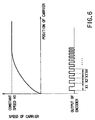
- the width of the output pulse from the encoder 7 will change gradually. If damping has occurred, the waveform of the output pulse from the encoder 7 will be corrupted in such a manner that, for example, the width of the pulse will become shorter or longer as shown in FIG. 15. Sensing the corruption of the pulse width determines whether the acceleration is stable or whether the speed of the carrier has fluctuated or damping has occurred. Specifically, in FIG. 6, if expression X1 > X2 > X3 > X4 ...> Xn is fulfilled, it will be judged that the waveform of the output pulse from the encoder 7 is normal (or that the speed of the carrier has not fluctuated). If the expression is not fulfilled, it will be judged that the waveform of the output pulse from the encoder 7 is not normal (or that the speed of the carrier has fluctuated).
- step 23 If it has been judged at ST22 that the waveform of the output pulse is not normal or that the speed of the carrier has fluctuated, the amount of acceleration of the carrier motor 6 will be decreased at step 23 (ST23) and control be returned to ST22. By doing this, stable acceleration control can be achieved as shown in FIG. 6 where the width of the output pulse from the encoder 7 becomes shorter gradually.
- control will be returned to ST4 in FIGS. 3A and 3B.
- print output control will be started at ST6. Namely, one line of output will be printed on the basis of the printing data received from the host computer 24.
- control will be returned to ST9. If it has been judged at ST10 that the carrier 3 has reached a position an X number of characters ahead of the print end position, deceleration control of the carrier motor 6 involving deceleration suppression will be performed at ST11.
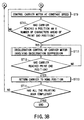
- the carrier motor 6 is decelerated by controlling the carrier motor 6 on the basis of the preset deceleration data at step 31 (ST31). As in acceleration control of the carrier motor 6, it is judged at step 32 (ST32) whether the waveform of the output pulse from the encoder 7 is normal (or the waveform changes smoothly with no damping). This determines whether the speed of the carrier has fluctuated or damping has occurred.
- step 33 the amount of deceleration of the carrier motor 6 will be decreased at step 33 (ST33) and control be returned to ST32. By doing this, deceleration control is achieved stably while suppressing the fluctuation of the speed of the carrier. If it has been judged at ST32 that the waveform of the output pulse from the encoder 7 is normal or that the speed of the carrier has not fluctuated, control will be returned to ST12 in FIGS. 3A and 3B.
- step 14 it is judged at step 14 (ST14) whether all the printing has been done. If it has been judged at ST14 that all the printing has not been completed, control will be returned to ST3. If it has been judged at ST14 that all the printing has been completed, the printing control will be ended.
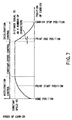
- the waveform of the output pulse from the encoder 7 is monitored in acceleration control of the carrier motor 6. If a fluctuation in the speed of the carrier, such as the corruption of the waveform, has been sensed, the smooth acceleration of the carrier 3 will be maintained by reducing the amount of acceleration. At the same time, the carrier will be controlled so that it may reach a specific print start position in the direction of main scanning before the speed of the carrier reaches the constant speed V0 as shown in FIG. 7.
- the carrier can be brought into a print output enable state before the speed of the carrier has reached the constant speed V0, or in the course of acceleration control.
- This makes it possible to secure a sufficient distance needed for acceleration of the carrier 3 without lengthening the moving range of the carrier, even when printing is done at high speed. Because stable speed control is performed during acceleration control, even when printing is done during acceleration control, the printing can be effected at high speed without degrading the quality of the result of printing.
- the waveform of the output pulse from the encoder 7 is monitored. If a fluctuation in the speed of the carrier, such as the corruption of the waveform, has been sensed, the amount of the deceleration will be decreased. This secures the smooth deceleration of the carrier 3 and brings the carrier into deceleration control before the carrier has reached the print end position (or when the carrier has reached a place an X number of characters ahead of the print end position) as shown in FIG. 7.
- the carrier 3 can be brought into the print output enable state even in the course of deceleration control. This makes it possible to secure a sufficient distance needed for deceleration of the carrier 3 without lengthening the moving range of the carrier, even when printing is done at high speed.
- the moving range of the carrier 3 can be made shorter while securing the quality of printing, the entire size of the printer can be made smaller and its cost be reduced.
- the present invention has been applied to one-side printing control.
- printing is done when the carrier moves forward, whereas printing is not effected when the carrier returns to the home position.
- the invention may be applied to two-way printing control in which printing is done not only when the carrier moves forward but also when it returns to the home position.
- the present invention may be applied to not only a wire dot printer but also other general printers that print while moving the print head in the direction of main scanning, such as a thermal printer or an ink-jet printer.
- FIGS. 8A to 11 A diagram illustrating the configuration of the wire dot printer of the second embodiment and its vicinities and a block diagram of the wire dot printer are the same as those in FIGS. 1 and 2, so a detailed explanation of them will not be given.
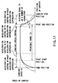
- the second embodiment differs from the first embodiment in that acceleration suppression of the carrier 3 is performed during the time from when the carrier has entered the printable range V until it has reached the constant speed V0 as shown in FIG. 11.
- acceleration control of the carrier 3 is performed during the time from when acceleration control of the carrier 3 has been started until the carrier has reached the constant speed V0.
- the CPU 11 of the second embodiment is designed to perform printing control as shown in FIGS. 8A and 8B.
- the processes at steps 51 (ST51) to 54 (ST54) of FIGS. 8A and 8B are the same as those at ST1 to ST4 of FIGS. 3A and 3B.
- acceleration control of the carrier motor 6 without acceleration suppression will be performed at ST55. That is, only acceleration control of the carrier motor 6 will be performed without monitoring a fluctuation in the speed of the carrier as shown in FIG. 9.
- the carrier 3 has not entered the printable range V yet at this time, the presence or absence of a fluctuation in the speed of the carrier need not be considered. This makes it possible to set the acceleration data so that acceleration control may be performed in a shorter distance than in the first embodiment.
- steps 56 (ST56) to 60 (ST60) are the same as those at ST6 to ST10 of FIGS. 3A and 3B.
- step 58 performs acceleration control of the carrier motor 6 with suppressing acceleration. That is the processes shown in FIG. 4 are performed.
- step 61 If it has been judged at ST60 that the carrier 3 has reached a position an X number of characters ahead of the print start position, deceleration control of the carrier motor 6 involving deceleration suppression will be performed at step 61 (ST61). That is, the processes shown in FIG. 5 will be performed.
- step 62 it is judged at step 62 (ST62) whether the carrier 3 has reached the print end position. If it has been judged at ST62 that the carrier 3 has not reached the print end position, control will be returned to ST61. If it has been judged at ST63 that the carrier 3 has reached the print end position, deceleration control of the carrier motor 6 without deceleration suppression will be performed at step 63 (ST63). That is, only deceleration control of the carrier motor 6 will be performed without monitoring a fluctuation in the speed of the carrier as shown in FIG. 10.
- the carrier 3 has passed the printable range V, the presence or absence of a fluctuation in the speed of the carrier need not be considered. This makes it possible to set the deceleration data so that the carrier may be decelerated in a shorter distance than in the first embodiment.
- step 64 it is judged at step 64 (ST64) whether the carrier 3 has reached the print stop position. If it has been judged at ST64 that the carrier 3 has not reached the print stop position, control will be returned to the process at ST63. If it has been judged at ST64 that the carrier 3 has reached the print stop position, reverse control of the carrier motor 6 will be performed at step 65 (ST65) to return the carrier 3 to the home position.
- acceleration control of the carrier 3 during the time from when the carrier 3 has started to be driven until the carrier 3 has entered the printable range V, acceleration control without acceleration suppression is performed. During the time from when the carrier has entered the printable range V until the carrier has reached the constant speed V0, acceleration control involving acceleration suppression is performed.
- the acceleration data can be set so that acceleration control may be performed in a shorter distance than in the first embodiment (shown by a dot-dash line in FIG. 11). This makes it possible to print at higher speed without degrading the quality of the result of printing and shorten the moving range W of the carrier.
- deceleration control of the carrier 3 In deceleration control of the carrier 3, too, deceleration with deceleration suppression is performed until the carrier 3 has passed the printable range V. After the carrier 3 has passed the printable range V, deceleration control without deceleration control is performed.
- the deceleration data can be set so that deceleration control may be performed in a shorter distance than in the first embodiment. This makes it possible to print at higher speed without degrading the quality of the result of printing and shorten the moving range W of the carrier.
- FIGS. 12 and 13 A diagram illustrating the configuration of the wire dot printer of the third embodiment and its vicinities and a block diagram of the wire dot printer are the same as those in FIGS. 1 and 2, so a detailed explanation of them will not be given.
- the flowchart for printing control performed by the CPU 11 of the third embodiment is the same as that of FIGS. 8A and 8B in the second embodiment.
- the third embodiment differs in printing control from the second embodiment in that at ST55, the carrier is accelerated at a stretch to a preset specific speed V1 lower than the constant speed V0 in acceleration control of the carrier motor 6 without acceleration suppression performed until the carrier has entered the printable range.
- the carrier is accelerated at a stretch to a preset specific speed V1 lower than the constant speed V0 in acceleration control of the carrier motor 6 without acceleration suppression performed until the carrier has entered the printable range.
- only acceleration control of the carrier 3 is performed in acceleration control of the carrier motor 6 without acceleration control performed until the carrier has entered the printable range.
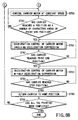
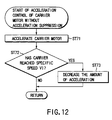
- the CPU 11 if the CPU 11 has judged at ST54 in FIGS. 8A and 8B that the carrier 3 has not reached the print start position, it will perform acceleration control of the carrier motor 6 without acceleration suppression at ST54 as shown in FIG. 12. Namely, the carrier motor 6 is accelerated on the basis of the preset acceleration data at ST71. In this case, the acceleration data has only to be set so that the speed of the carrier may reach a specific speed V1 before the carrier reaches the print start position.
- step 72 it is judged at step 72 (ST72) whether the speed of the carrier has reached the specific speed V1. If it has been judged at ST72 that the speed of the carrier has not reached the specific speed V1, control will be returned to ST54. If it has been judged at ST72 that the speed of the carrier has reached the specific speed V1, the amount of acceleration will be reduced at step 73 (ST73) so that the acceleration of the carrier 3 may enter the printable range V more stably and control will be returned to ST54 in FIGS. 8A and 8B.
- the speed of the carrier is accelerated at a stretch to the specific speed V1 preset lower than the constant speed V0, which brings the carrier 3 to the speed V1 faster than in the second embodiment before it has reached the print start position, when the presence or absence of a fluctuation in the speed of the carrier need not be considered. Therefore, the acceleration data can be set so that acceleration control may be performed in a shorter distance than in the second embodiment. This makes it possible to print at much higher speed without degrading the quality of the result of printing and make the carrier moving range W still shorter.
- the speed of the carrier can be brought to the constant speed V0 faster than in the second embodiment by bringing the carrier 3 to the still faster speed V1 before the carrier has reached the print start position, when the presence or absence of a fluctuation in the speed of the carrier need not be considered. This makes it possible to shorten the distance required for acceleration control without acceleration suppression in FIG. 11 and prevent the distance for constant-speed control to keep the constant speed V0 from becoming shorter.
- acceleration control with acceleration suppression is performed during the time from when the carrier has entered the printable range V until the speed of the carrier has reached the constant speed V0. Therefore, the acceleration data can be set so that acceleration control may be performed in a shorter distance before the carrier has reached the print start position, when the presence or absence of a fluctuation in the speed of the carrier need not be considered. This makes it possible to print at still higher speed without degrading the quality of the result of printing and shorten the carrier moving range W.
- deceleration control of the carrier deceleration control with deceleration suppression is performed until the carrier has passed the printable range V. Therefore, the deceleration data can be set so that deceleration control may be performed in a shorter distance after the carrier has passed the print end position, when the presence or absence of a fluctuation in the speed of the carrier need not be considered. This makes it possible to print at still higher speed without degrading the quality of the result of printing and shorten the carrier moving range W.
- the speed of the carrier can be brought to a constant speed still faster by bringing the carrier to a still faster speed before the carrier has reached the print start position, when the presence or absence of a fluctuation in the speed of the carrier need not be considered. This prevents the distance needed for constant-speed control to keep the constant speed from becoming shorter.
Landscapes
- Character Spaces And Line Spaces In Printers (AREA)
- Dot-Matrix Printers And Others (AREA)
- Impact Printers (AREA)
Applications Claiming Priority (4)
| Application Number | Priority Date | Filing Date | Title |
|---|---|---|---|
| JP5645898 | 1998-03-09 | ||
| JP5645898 | 1998-03-09 | ||
| JP35903898A JP3579274B2 (ja) | 1998-03-09 | 1998-12-17 | シリアルプリンタ |
| JP35903898 | 1998-12-17 |
Publications (3)
| Publication Number | Publication Date |
|---|---|
| EP0941864A2 true EP0941864A2 (de) | 1999-09-15 |
| EP0941864A3 EP0941864A3 (de) | 2000-12-20 |
| EP0941864B1 EP0941864B1 (de) | 2002-10-16 |
Family
ID=26397402
Family Applications (1)
| Application Number | Title | Priority Date | Filing Date |
|---|---|---|---|
| EP99104464A Expired - Lifetime EP0941864B1 (de) | 1998-03-09 | 1999-03-05 | Seriendrucker mit Wagenbeschleunigungssteuerung |
Country Status (7)
| Country | Link |
|---|---|
| US (1) | US6139205A (de) |
| EP (1) | EP0941864B1 (de) |
| JP (1) | JP3579274B2 (de) |
| KR (1) | KR100312059B1 (de) |
| CN (1) | CN1105651C (de) |
| DE (1) | DE69903488T2 (de) |
| SG (1) | SG68094A1 (de) |
Cited By (3)
| Publication number | Priority date | Publication date | Assignee | Title |
|---|---|---|---|---|
| WO2009016328A1 (en) * | 2007-07-27 | 2009-02-05 | Quill Coding Solutions Limited | Marking system with integrated linearity synchronisation |
| US7585123B2 (en) | 2001-08-22 | 2009-09-08 | Brother Kogyo Kabushiki Kaisha | Image forming apparatus |
| US7591518B2 (en) | 2001-08-22 | 2009-09-22 | Brother Kogyo Kabushiki Kaisha | Image forming apparatus |
Families Citing this family (13)
| Publication number | Priority date | Publication date | Assignee | Title |
|---|---|---|---|---|
| JP3715850B2 (ja) * | 1999-11-08 | 2005-11-16 | キヤノン株式会社 | モータ制御装置及び該装置を用いたプリンタ |
| DE60000962T2 (de) * | 2000-01-20 | 2003-08-28 | Hewlett-Packard Co. (N.D.Ges.D.Staates Delaware), Palo Alto | Drucker mit Druckmodus zum nur in einer Richtung drucken |
| JP4174972B2 (ja) * | 2001-02-09 | 2008-11-05 | 三菱電機株式会社 | 位置決め制御方法 |
| JP3814509B2 (ja) * | 2001-10-01 | 2006-08-30 | キヤノン株式会社 | モータの制御のための方法及び装置 |
| US6935795B1 (en) | 2004-03-17 | 2005-08-30 | Lexmark International, Inc. | Method for reducing the effects of printhead carrier disturbance during printing with an imaging apparatus |
| JP4572558B2 (ja) * | 2004-03-30 | 2010-11-04 | ブラザー工業株式会社 | 印刷装置 |
| US20050225626A1 (en) * | 2004-03-31 | 2005-10-13 | Seiko Epson Corporation | Printing method, medium detection method, computer-readable storage medium, and printing apparatus |
| US8287063B2 (en) * | 2006-12-15 | 2012-10-16 | Dandong Unik Textile., Ltd | Intelligent waterless printing and dyeing control equipment and control method thereof |
| JP2010052417A (ja) * | 2008-07-29 | 2010-03-11 | Ricoh Co Ltd | 画像形成装置 |
| JP5779896B2 (ja) * | 2011-02-08 | 2015-09-16 | セイコーエプソン株式会社 | 記録装置、および、記録装置の制御方法 |
| JP6003156B2 (ja) * | 2012-03-30 | 2016-10-05 | ブラザー工業株式会社 | 画像形成装置 |
| JP6458689B2 (ja) * | 2015-09-10 | 2019-01-30 | 株式会社デンソー | モータ制御装置 |
| EP3582390A4 (de) * | 2017-02-09 | 2020-01-01 | Fuji Corporation | Motorsteuerungsvorrichtung und speiser |
Family Cites Families (16)
| Publication number | Priority date | Publication date | Assignee | Title |
|---|---|---|---|---|
| JPS5859876A (ja) * | 1981-10-07 | 1983-04-09 | Seiko Epson Corp | プリンタのキャリッジ制御装置 |
| US4469460A (en) * | 1982-09-30 | 1984-09-04 | International Business Machines Corporation | Matrix printer with optimum printing velocity |
| JPS62173262A (ja) * | 1986-01-27 | 1987-07-30 | Oki Electric Ind Co Ltd | シリアルドツトプリンタの印字制御方法 |
| JP2563788B2 (ja) * | 1986-03-07 | 1996-12-18 | セイコーエプソン株式会社 | プリンタのキヤリツジ制御方法 |
| JPH0780330B2 (ja) * | 1988-01-06 | 1995-08-30 | 日本電気株式会社 | プリンタの印字ヘッド移動制御装置 |
| US4827282A (en) * | 1988-09-01 | 1989-05-02 | Eastman Kodak Company | Print head assembly acceleration control method |
| US5207520A (en) * | 1989-10-03 | 1993-05-04 | Seiko Epson Corp. | Printer carriage acceleration control device |
| DE4107036A1 (de) * | 1990-03-19 | 1991-09-26 | Mannesmann Ag | Verfahren zum schwingungsarmen anfahren des wagenantriebsmotors in druckeinrichtungen |
| JPH0557982A (ja) * | 1991-09-02 | 1993-03-09 | Canon Inc | キヤリツジ駆動方法 |
| JPH05338306A (ja) * | 1992-06-11 | 1993-12-21 | Fuji Xerox Co Ltd | シリアルプリンタ |
| JPH06335275A (ja) * | 1993-05-24 | 1994-12-02 | Nec Corp | 印字ヘッドキャリジ速度制御方式 |
| JPH0725103A (ja) * | 1993-07-15 | 1995-01-27 | Canon Inc | プリンタ装置及びプリント方法 |
| US5627947A (en) * | 1993-10-29 | 1997-05-06 | Hewlett-Packard Company | Variable-duration printer carriage motor acceleration method and apparatus |
| JPH07329388A (ja) * | 1994-06-03 | 1995-12-19 | Canon Inc | 記録装置および情報処理システム |
| JP3048110B2 (ja) * | 1994-07-15 | 2000-06-05 | セイコーエプソン株式会社 | シリアル・プリンタのキャリッジ制御装置 |
| US5563591A (en) * | 1994-10-14 | 1996-10-08 | Xerox Corporation | Programmable encoder using an addressable display |
-
1998
- 1998-12-17 JP JP35903898A patent/JP3579274B2/ja not_active Expired - Fee Related
-
1999
- 1999-03-03 US US09/261,332 patent/US6139205A/en not_active Expired - Fee Related
- 1999-03-05 KR KR1019990007244A patent/KR100312059B1/ko not_active Expired - Fee Related
- 1999-03-05 DE DE69903488T patent/DE69903488T2/de not_active Expired - Fee Related
- 1999-03-05 EP EP99104464A patent/EP0941864B1/de not_active Expired - Lifetime
- 1999-03-08 SG SG1999001069A patent/SG68094A1/en unknown
- 1999-03-09 CN CN99103935A patent/CN1105651C/zh not_active Expired - Fee Related
Cited By (8)
| Publication number | Priority date | Publication date | Assignee | Title |
|---|---|---|---|---|
| US7585123B2 (en) | 2001-08-22 | 2009-09-08 | Brother Kogyo Kabushiki Kaisha | Image forming apparatus |
| US7591518B2 (en) | 2001-08-22 | 2009-09-22 | Brother Kogyo Kabushiki Kaisha | Image forming apparatus |
| EP1970207A3 (de) * | 2001-08-22 | 2009-10-07 | Brother Kogyo Kabushiki Kaisha | Bilderzeugungsvorrichtung |
| EP2266806A1 (de) * | 2001-08-22 | 2010-12-29 | Brother Kogyo Kabushiki Kaisha | Bilderzeugungsvorrichtung |
| EP2269831A1 (de) * | 2001-08-22 | 2011-01-05 | Brother Kogyo Kabushiki Kaisha | Bilderzeugungsvorrichtung |
| US8348403B2 (en) | 2001-08-22 | 2013-01-08 | Brother Kogyo Kabushiki Kaisha | Image forming apparatus |
| WO2009016328A1 (en) * | 2007-07-27 | 2009-02-05 | Quill Coding Solutions Limited | Marking system with integrated linearity synchronisation |
| GB2463847A (en) * | 2007-07-27 | 2010-03-31 | Quill Coding Solutions Ltd | Marking system with integrated linearity sychronisation |
Also Published As
| Publication number | Publication date |
|---|---|
| EP0941864A3 (de) | 2000-12-20 |
| KR100312059B1 (ko) | 2001-11-03 |
| JP3579274B2 (ja) | 2004-10-20 |
| CN1105651C (zh) | 2003-04-16 |
| US6139205A (en) | 2000-10-31 |
| DE69903488D1 (de) | 2002-11-21 |
| DE69903488T2 (de) | 2003-03-20 |
| KR19990077615A (ko) | 1999-10-25 |
| CN1236706A (zh) | 1999-12-01 |
| EP0941864B1 (de) | 2002-10-16 |
| JPH11321005A (ja) | 1999-11-24 |
| SG68094A1 (en) | 1999-10-19 |
Similar Documents
| Publication | Publication Date | Title |
|---|---|---|
| EP0941864B1 (de) | Seriendrucker mit Wagenbeschleunigungssteuerung | |
| US6315471B1 (en) | Apparatus for controlling ribbon tension in a thermal printer | |
| US5189436A (en) | Recording method that selects a movement velocity in conformity with a recognized recording width to accomplish recording and recording apparatus using the same method | |
| US6969141B2 (en) | Ink jet recording apparatus and ink jet recording method | |
| US6618159B1 (en) | Method of switching print modes of printing device | |
| JP3674220B2 (ja) | プリンタ及びその記録紙ジャム処理方法 | |
| JPH11138872A (ja) | サーマル式プリンタ | |
| US6196661B1 (en) | Serial recording apparatus | |
| EP0390125B1 (de) | Verfahren und Apparat zur Aufzeichung | |
| JPH0867045A (ja) | プリンタ | |
| JPH02158367A (ja) | プリンタ制御方法 | |
| JP3624685B2 (ja) | プリンタ | |
| US5382104A (en) | Printing apparatus | |
| JP4591646B2 (ja) | 印字装置の制御装置 | |
| JPH1191089A (ja) | インクジェット式記録装置 | |
| JP2001219612A (ja) | シリアルプリンタ | |
| JPH03231869A (ja) | サーマルプリンタ | |
| JPH0899443A (ja) | シリアル記録装置 | |
| JP2007044947A (ja) | 記録装置 | |
| JP3383062B2 (ja) | 印字装置とその改行方法 | |
| JPH01290464A (ja) | 液体噴射記録装置 | |
| JP3642932B2 (ja) | プリンタのカッタ機構及びカッタ機構付きプリンタ | |
| JPH10109452A (ja) | シリアルプリンタ | |
| JP2979512B2 (ja) | ヘッドギャップ調整方法及びヘッドギャップ調整制御装置 | |
| JP2002192787A (ja) | シリアルプリンタ |
Legal Events
| Date | Code | Title | Description |
|---|---|---|---|
| PUAI | Public reference made under article 153(3) epc to a published international application that has entered the european phase |
Free format text: ORIGINAL CODE: 0009012 |
|
| 17P | Request for examination filed |
Effective date: 19990326 |
|
| AK | Designated contracting states |
Kind code of ref document: A2 Designated state(s): DE FR GB IT |
|
| AX | Request for extension of the european patent |
Free format text: AL;LT;LV;MK;RO;SI |
|
| PUAL | Search report despatched |
Free format text: ORIGINAL CODE: 0009013 |
|
| AK | Designated contracting states |
Kind code of ref document: A3 Designated state(s): AT BE CH CY DE DK ES FI FR GB GR IE IT LI LU MC NL PT SE |
|
| AX | Request for extension of the european patent |
Free format text: AL;LT;LV;MK;RO;SI |
|
| AKX | Designation fees paid |
Free format text: DE FR GB IT |
|
| GRAG | Despatch of communication of intention to grant |
Free format text: ORIGINAL CODE: EPIDOS AGRA |
|
| 17Q | First examination report despatched |
Effective date: 20020109 |
|
| GRAG | Despatch of communication of intention to grant |
Free format text: ORIGINAL CODE: EPIDOS AGRA |
|
| GRAH | Despatch of communication of intention to grant a patent |
Free format text: ORIGINAL CODE: EPIDOS IGRA |
|
| GRAH | Despatch of communication of intention to grant a patent |
Free format text: ORIGINAL CODE: EPIDOS IGRA |
|
| GRAA | (expected) grant |
Free format text: ORIGINAL CODE: 0009210 |
|
| AK | Designated contracting states |
Kind code of ref document: B1 Designated state(s): DE FR GB IT |
|
| REG | Reference to a national code |
Ref country code: GB Ref legal event code: FG4D |
|
| REF | Corresponds to: |
Ref document number: 69903488 Country of ref document: DE Date of ref document: 20021121 |
|
| ET | Fr: translation filed | ||
| PLBI | Opposition filed |
Free format text: ORIGINAL CODE: 0009260 |
|
| PLAX | Notice of opposition and request to file observation + time limit sent |
Free format text: ORIGINAL CODE: EPIDOSNOBS2 |
|
| 26 | Opposition filed |
Opponent name: DREWES BERNHARD Effective date: 20030715 |
|
| PLAX | Notice of opposition and request to file observation + time limit sent |
Free format text: ORIGINAL CODE: EPIDOSNOBS2 |
|
| PLBB | Reply of patent proprietor to notice(s) of opposition received |
Free format text: ORIGINAL CODE: EPIDOSNOBS3 |
|
| PLBD | Termination of opposition procedure: decision despatched |
Free format text: ORIGINAL CODE: EPIDOSNOPC1 |
|
| PLBP | Opposition withdrawn |
Free format text: ORIGINAL CODE: 0009264 |
|
| PLBM | Termination of opposition procedure: date of legal effect published |
Free format text: ORIGINAL CODE: 0009276 |
|
| STAA | Information on the status of an ep patent application or granted ep patent |
Free format text: STATUS: OPPOSITION PROCEDURE CLOSED |
|
| 27C | Opposition proceedings terminated |
Effective date: 20070906 |
|
| PGFP | Annual fee paid to national office [announced via postgrant information from national office to epo] |
Ref country code: GB Payment date: 20090304 Year of fee payment: 11 |
|
| PGFP | Annual fee paid to national office [announced via postgrant information from national office to epo] |
Ref country code: IT Payment date: 20090319 Year of fee payment: 11 Ref country code: DE Payment date: 20090226 Year of fee payment: 11 |
|
| PGFP | Annual fee paid to national office [announced via postgrant information from national office to epo] |
Ref country code: FR Payment date: 20090316 Year of fee payment: 11 |
|
| GBPC | Gb: european patent ceased through non-payment of renewal fee |
Effective date: 20100305 |
|
| REG | Reference to a national code |
Ref country code: FR Ref legal event code: ST Effective date: 20101130 |
|
| PG25 | Lapsed in a contracting state [announced via postgrant information from national office to epo] |
Ref country code: FR Free format text: LAPSE BECAUSE OF NON-PAYMENT OF DUE FEES Effective date: 20100331 |
|
| PG25 | Lapsed in a contracting state [announced via postgrant information from national office to epo] |
Ref country code: DE Free format text: LAPSE BECAUSE OF NON-PAYMENT OF DUE FEES Effective date: 20101001 |
|
| PG25 | Lapsed in a contracting state [announced via postgrant information from national office to epo] |
Ref country code: GB Free format text: LAPSE BECAUSE OF NON-PAYMENT OF DUE FEES Effective date: 20100305 Ref country code: IT Free format text: LAPSE BECAUSE OF NON-PAYMENT OF DUE FEES Effective date: 20100305 |