EP0942119A2 - Dispositif pour rehausser un pylÔne haute tension - Google Patents
Dispositif pour rehausser un pylÔne haute tension Download PDFInfo
- Publication number
- EP0942119A2 EP0942119A2 EP99104465A EP99104465A EP0942119A2 EP 0942119 A2 EP0942119 A2 EP 0942119A2 EP 99104465 A EP99104465 A EP 99104465A EP 99104465 A EP99104465 A EP 99104465A EP 0942119 A2 EP0942119 A2 EP 0942119A2
- Authority
- EP
- European Patent Office
- Prior art keywords
- mast
- lifting
- tower
- lifting frame
- rope
- Prior art date
- Legal status (The legal status is an assumption and is not a legal conclusion. Google has not performed a legal analysis and makes no representation as to the accuracy of the status listed.)
- Granted
Links
- 238000009434 installation Methods 0.000 abstract 1
- XEEYBQQBJWHFJM-UHFFFAOYSA-N Iron Chemical compound [Fe] XEEYBQQBJWHFJM-UHFFFAOYSA-N 0.000 description 4
- 238000000034 method Methods 0.000 description 4
- 238000010276 construction Methods 0.000 description 2
- 229910052742 iron Inorganic materials 0.000 description 2
- 230000005540 biological transmission Effects 0.000 description 1
- 239000000969 carrier Substances 0.000 description 1
- 238000006073 displacement reaction Methods 0.000 description 1
- 230000000694 effects Effects 0.000 description 1
- 230000005611 electricity Effects 0.000 description 1
- 238000005259 measurement Methods 0.000 description 1
- 230000006641 stabilisation Effects 0.000 description 1
- 238000011105 stabilization Methods 0.000 description 1
Images


Classifications
-
- E—FIXED CONSTRUCTIONS
- E04—BUILDING
- E04H—BUILDINGS OR LIKE STRUCTURES FOR PARTICULAR PURPOSES; SWIMMING OR SPLASH BATHS OR POOLS; MASTS; FENCING; TENTS OR CANOPIES, IN GENERAL
- E04H12/00—Towers; Masts or poles; Chimney stacks; Water-towers; Methods of erecting such structures
- E04H12/34—Arrangements for erecting or lowering towers, masts, poles, chimney stacks, or the like
Definitions
- the invention relates to a device for raising an overhead line mast according to the preamble of claim 1.
- DE 4301467 A1 describes a method and a device for lengthening an operating overhead line mast known.
- This is a lifting device placed on the transmission tower to be extended and in at least two to each other spaced planes connected to the mast. Subsequently the mast is separated from its mast base and then the mast follows using the connected to the lifting device until it reaches the desired height Has.
- a prepared mast part is inserted into the gap and also with the raised mast and connected to the mast base. After loosening the connection the lifting device is removed with the mast.
- the lifting device has Supports that are evenly distributed around the mast and with each other as well are connected to the mast. Lifting devices interact with the supports and serve to raise the mast so far from the mast base that the prepared extension part can be inserted between mast and mast base.
- the invention has for its object a device for increasing a Specify overhead line masts of the type mentioned, the universal for different Voltage levels is suitable and relatively low investment costs required.
- the advantages which can be achieved with the invention consist in particular in that the proposed universal for different voltage levels (110 kV, 220 kV, 380 kV) suitable master elevation device in comparison to the known master elevation device has smaller dimensions and a lower weight and consists of fewer components. For example, this has advantageous positive ones Effects of transporting the master elevation facility. Furthermore the necessary investment costs are lower, especially if the assembly tower composed of commercially available, technically mature tower pieces is how they are tested and used for construction cranes.
- the time required for uncomplicated assembly and disassembly and the The size of the required assembly column is reduced because, for example, the ones used Components due to reduced weight and reduced dimensions are easy to use.
- For setting up and dismantling the master elevation device little space is required. There is only minimal damage to the land. All in all this results in an increased efficiency of the master elevation facility.
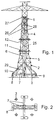
- Fig. 1 is a side view of a mast elevation device connected to an overhead line mast shown. It is an electricity pylon with a four outer one Masteckstiele 4 mast part 1, one connected to mast foundations 3 Lower mast part 2 and an interchangeable mast intermediate section 5 detect.
- the master elevation device basically consists of a lifting device and lifting equipment.
- the lifting device consists of one several tower pieces assembled assembly tower 6, a foundation cross 7 with foundation plates 8 and threaded spindles 9, support bars 10 for stabilization the one placed on the foundation cross and connected to it Assembly tower 6, a lower lifting frame 11 and an upper lifting frame 12. If necessary, more than two lifting frames can also be provided.
- Assembly tower 6 can use commercial building components as they are offered for construction cranes. The same goes for that Foundation cross 7, the foundation plates 8 and the support bars 10.
- Essentials Characteristic of the embodiment according to FIG. 1 is that the assembly tower 6 completely is set up free-standing.
- the lifting means consist of one or more lifting ropes 25, if necessary lower and upper tension compensation ropes 26, pulley pulleys 27, if necessary lower and upper rope compensation rollers 28 and at least one traction device 29 (Gripping hoist, chain hoist or winch).
- FIGS. 4 to 6 are plan views of a foundation cross of the master elevation device shown.
- the foundation cross 7 is based on the between the mast foundations 3 arranged foundation plates 8 on the ground.
- one runs first rope connection of the lifting means between the only one on the foundation cross 7 anchored towing device 29 via a running in the center of the assembly tower 6 Lifting rope 25 to the lower rope compensation roller 28.
- a second rope connection of the lifting means runs over the lower tension compensation cable 26 between the lower and upper Rope leveling rollers 28.
- a third rope connection of the lifting means runs over the upper one Tension compensation ropes 26 between upper rope compensation rollers 28 and rope deflection rollers 27.
- Fig. 12 for details. This embodiment of the lifting means is only exemplary and other design variants can be used, 10 and 11 show.
- the symmetrical lifting frame consists of eight Connecting beams of the same length, namely four outer connecting beams 13 and four inner connecting beams 14 assembled, four corner post clamps 16 for connecting the outer connection carrier 13 to one another and serve with the Masteckstielen 4.
- the connection between inner and outer Connection carriers 13, 14 are made via a plurality of connection terminals 30.
- the inner connection carrier 14 delimit an inner one for pushing through the Assembly tower 6 suitable square, being in each corner area of this square in each case two guide rollers 15 are fastened to the inner connecting supports 14. These guide rollers 15 slide along the outer surfaces of the four corner posts Assembly tower 6. This results in a horizontal plane through the assembly tower 6 limited, but vertically free mobility of the lifting frame and thus that connected to the lifting frame 11, 12 via the corner post clamps 16 Mast top 1.
- the lifting frames 11, 12 described above have the advantage that they are made of consist of a few, partly identical parts, continuously over a wide range are adjustable to adapt the lifting frame to the dimensions of the top part of the mast, and can be quickly and safely mounted on the mast corner stems 4.
- the Corner handle clamp 16 consists of a bracket 17 for receiving the two outer, Connection carrier 13 arranged at right angles to one another, on bracket 17 mounting clamp 18, one mounted on bracket 17, preferably welded Angle plate 19 for receiving a mast post 4 and one at the Angle plate 19 clamps to be mounted 20.
- a bracing supported on the clamp 20 Clamping screw 21 is used to press the mast handle 4 against the Angle plate 19 and thus for securely fixing the lifting frame to the mast handle.
- FIG. 6 shows a top view of an assembled corner handle clamp 16. There are the two outer connecting beams pressed together by means of the clamping iron 18 13 of the lifting frame and the angle plate 19 / clamping arm via the configuration 20 / Clamping screw 21 on mast frame handle 4 fixed.
- FIG. 7 shows a side view of an assembled connecting clamp 30.
- the connecting terminal 30 consists of a bracket 23 for receiving an outer Connection carrier 13 and an inner arranged at right angles thereto Connection carrier 14 and a clamping iron 24 to be attached to the bracket 23 for jamming the two connecting beams.
- FIG. 8 shows a top view of an assembled connecting clamp 30, wherein the two connecting beams 13, 14 clamp arms 24 pressing against each other can be seen.
- the assembly tower in the middle of the mast can be set up quickly and easily. Auxiliary roles are attached to the mast top 1, with their help and using of auxiliary ropes brought the individual within the mast base 2 Tower sections raised and into those required for connection to other tower sections Position.
- the connection between the individual tower sections takes place via quickly screwable butt joints, whereby it it is essential that continuous guide surfaces for the Form guide rollers 15.
- the actuation of the threaded spindles 9 is required.
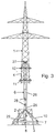
- FIG. 3 is a side view of the master elevation device with the raised Mast top part shown and shows the process step in which a prepared, Intermediate mast intercept, not shown, with electrical lines in operation can be mounted between the upper mast part 1 and lower mast part 2.
- This The process step is preceded by the dismantling of the intermediate mast section shown in FIG. 1 5 and the subsequent vertical displacement of the with the lifting frame 11, 12 connected mast part 1 along the assembly tower 6 upwards.
- the lifting rope 25 is retracted by the traction device 29, whereby the rope compensation rollers 28 move vertically downwards.
- the rope balancing rollers 28 result from the upper tension balancing ropes 26 and the cable pulleys 27 a vertical upward movement of the lifting frame 11, 12 with the mast top 1.
- the lifting equipment and the Disassembled lifting device Since the assembly tower 6, as already mentioned, according to the The modular principle is composed of several individual tower sections the disassembly as well as the assembly with the help of the mast upper part Auxiliary rollers and auxiliary ropes are relatively simple.
- FIG. 9 shows an alternative with regard to the support of the lifting device.
- the assembly tower 6 is supported on the ground rather, via a central foundation plate 31.
- the lower tower section or also several lower tower sections are with numerous lateral supports 32 with the Lower mast part 2 connected, which is itself anchored via the mast foundations 3.
- the attachment of the mast corner stems 4 of the mast top part 1 by means of guide rollers 15 along the assembly tower 6 movable lifting frame 11, 12 is as under the described above figures.
- the first variant according to FIG. 10 requires four lifting ropes 25, which are connected by four gripping cables 29 starting with a total of at least four rope pulleys 27 with the four Corners of the upper lifting frame 12 are connected. In the embodiment according to 10, a total of twelve cable pulleys 27 are provided.
- the connection of the lifting frame 12 on the mast posts 4 and along the corner posts of the Assembly tower 6 sliding guide rollers 15 of the lifting frame can be seen.
- the variant according to FIG. 11 has the advantage over the variant according to FIG. 10 that that only two grips 29 are required.
- the two reachings are over two lifting ropes 25 connected to two rope compensation rollers 28.
- the rope compensation rollers 28 lead two tension compensation cables 26, the ends of which are not shown, at the top Tower section of the assembly tower 6 attached rope pulleys with the four corners of the lifting frame are connected.
- the variant according to FIG. 12 has the advantage over the variant according to FIG. 11 that that only a single pulling device 29 is required (see also FIG. 1).
- This Traction device is connected to a lower rope compensation roller 28 via a lifting rope 25.
- This lower rope compensation roller 28 guides a lower tension compensation cable 26, the ends of which are connected to two upper rope compensation rollers 28.
- These top rope balancing rollers 28 in turn lead two upper tension compensation cables 26, the ends of which Not shown, attached to the upper tower section of the assembly tower 6 rope pulleys are connected to the four corners of the lifting frame.
- the variant according to Fig. 12 has the further advantage that an even pull on all automatically four Masteckstiele sets 4, without doing a tensile force measurement on each Masteckstiel This would require tilting of the upper mast part 1 during excluded from the lifting process.
- the lifting rope 25 and the traction device 29 are loaded less, the lifting rope be arranged in multiple strands over pulleys according to the pulley principle.
Landscapes
- Engineering & Computer Science (AREA)
- Architecture (AREA)
- Civil Engineering (AREA)
- Structural Engineering (AREA)
- Types And Forms Of Lifts (AREA)
- Electric Cable Installation (AREA)
- Refuge Islands, Traffic Blockers, Or Guard Fence (AREA)
- Current-Collector Devices For Electrically Propelled Vehicles (AREA)
Applications Claiming Priority (2)
| Application Number | Priority Date | Filing Date | Title |
|---|---|---|---|
| DE19810521 | 1998-03-11 | ||
| DE19810521A DE19810521A1 (de) | 1998-03-11 | 1998-03-11 | Vorrichtung zum Erhöhen eines Freileitungsmastes |
Publications (3)
| Publication Number | Publication Date |
|---|---|
| EP0942119A2 true EP0942119A2 (fr) | 1999-09-15 |
| EP0942119A3 EP0942119A3 (fr) | 2000-07-05 |
| EP0942119B1 EP0942119B1 (fr) | 2004-03-24 |
Family
ID=7860506
Family Applications (1)
| Application Number | Title | Priority Date | Filing Date |
|---|---|---|---|
| EP99104465A Expired - Lifetime EP0942119B1 (fr) | 1998-03-11 | 1999-03-05 | Dispositif pour rehausser un pylône haute tension |
Country Status (3)
| Country | Link |
|---|---|
| EP (1) | EP0942119B1 (fr) |
| AT (1) | ATE262634T1 (fr) |
| DE (2) | DE19810521A1 (fr) |
Cited By (2)
| Publication number | Priority date | Publication date | Assignee | Title |
|---|---|---|---|---|
| EP1247925A3 (fr) * | 2001-04-06 | 2003-11-12 | ABB PATENT GmbH | Dispositif pour rehausser des pylones de lignes à haute tension |
| GB2519722B (en) * | 2013-09-06 | 2016-09-14 | Brian Mirfin | Construction of mobile amusement rides having a tower |
Families Citing this family (2)
| Publication number | Priority date | Publication date | Assignee | Title |
|---|---|---|---|---|
| DE10164514C1 (de) * | 2001-12-19 | 2003-05-08 | Fbg Freileitungsbau Gmbh | Hebevorrichtung zur Erhöhung von Freileitungsmasten |
| DE102016110698A1 (de) | 2016-06-10 | 2017-12-14 | Ltb Leitungsbau Gmbh | Montagehilfskonstruktion und Verfahren zum Auswechseln eines Tragkonstruktionselements |
Citations (1)
| Publication number | Priority date | Publication date | Assignee | Title |
|---|---|---|---|---|
| DE4301467A1 (de) | 1993-01-21 | 1994-07-28 | Abb Patent Gmbh | Verfahren und Vorrichtung zum Verlängern eines im Betrieb befindlichen Freileitungsmastes |
Family Cites Families (8)
| Publication number | Priority date | Publication date | Assignee | Title |
|---|---|---|---|---|
| FR806727A (fr) * | 1936-05-25 | 1936-12-23 | Procédé de montage des constructions par tronçons successifs verticalement superposés, assemblés au sol | |
| FR1475767A (fr) * | 1966-01-31 | 1967-04-07 | Grue à mât télescopique | |
| DE2522158C2 (de) * | 1975-05-17 | 1986-01-23 | Epítéstudományi Intézet | Verfahren und Vorrichtung zum Fertigen der Betondecken mehrgeschossiger Gebäude |
| JPH04247175A (ja) * | 1991-01-28 | 1992-09-03 | Aichi Kinzoku Kogyo Kk | 送電用鉄塔の嵩上げ工法 |
| JPH04247176A (ja) * | 1991-01-28 | 1992-09-03 | Aichi Kinzoku Kogyo Kk | 送電用鉄塔の嵩上げ工法 |
| JP3090525B2 (ja) * | 1992-02-06 | 2000-09-25 | 岳南建設株式会社 | 送電鉄塔の嵩上げ工法及びその装置 |
| DE4445165C2 (de) * | 1994-12-17 | 2000-02-17 | Abb Patent Gmbh | Verfahren und Stockbaum zum Errichten von Gittermasten |
| DE19803954B4 (de) * | 1998-02-02 | 2008-02-14 | Edi.Son Energietechnik Gmbh | Verfahren und Vorrichtung zum Erhöhen von Masten |
-
1998
- 1998-03-11 DE DE19810521A patent/DE19810521A1/de not_active Withdrawn
-
1999
- 1999-03-05 AT AT99104465T patent/ATE262634T1/de not_active IP Right Cessation
- 1999-03-05 DE DE59908926T patent/DE59908926D1/de not_active Expired - Fee Related
- 1999-03-05 EP EP99104465A patent/EP0942119B1/fr not_active Expired - Lifetime
Patent Citations (1)
| Publication number | Priority date | Publication date | Assignee | Title |
|---|---|---|---|---|
| DE4301467A1 (de) | 1993-01-21 | 1994-07-28 | Abb Patent Gmbh | Verfahren und Vorrichtung zum Verlängern eines im Betrieb befindlichen Freileitungsmastes |
Cited By (6)
| Publication number | Priority date | Publication date | Assignee | Title |
|---|---|---|---|---|
| EP1247925A3 (fr) * | 2001-04-06 | 2003-11-12 | ABB PATENT GmbH | Dispositif pour rehausser des pylones de lignes à haute tension |
| GB2519722B (en) * | 2013-09-06 | 2016-09-14 | Brian Mirfin | Construction of mobile amusement rides having a tower |
| GB2542235A (en) * | 2013-09-06 | 2017-03-15 | Pondorfer Walter | Tower construction |
| GB2542235B (en) * | 2013-09-06 | 2018-01-17 | Pondorfer Walter | Assembling and disassembling mobile amusement rides |
| AU2013399904B2 (en) * | 2013-09-06 | 2018-04-26 | Mirfin, Brian | Tower construction |
| RU2657890C2 (ru) * | 2013-09-06 | 2018-06-18 | Вальтер ПОНДОРФЕР | Монтаж и демонтаж передвижных аттракционов |
Also Published As
| Publication number | Publication date |
|---|---|
| ATE262634T1 (de) | 2004-04-15 |
| DE59908926D1 (de) | 2004-04-29 |
| EP0942119B1 (fr) | 2004-03-24 |
| EP0942119A3 (fr) | 2000-07-05 |
| DE19810521A1 (de) | 1999-09-16 |
Similar Documents
| Publication | Publication Date | Title |
|---|---|---|
| DE69812624T2 (de) | Verfahren zum aufrichten eines mastes und vorrichtung dafür | |
| DE597417C (de) | Anordnung zum Aufhaengen eines aus mehreren parallel geschalteten Teilleitern gebildeten Buendelleiters | |
| EP3873840A1 (fr) | Procédé pour l'installation d'un système d'ascenseur | |
| EP0607915B1 (fr) | Méthode et dispositif pour allonger un pylÔne de lignes aériennes en opération | |
| EP0942119B1 (fr) | Dispositif pour rehausser un pylône haute tension | |
| EP0463552B1 (fr) | Dispositif d'amortisseur pour une ligne aérienne à haute tension | |
| EP0626339A1 (fr) | Pont roulant comportant une construction pour plateforme de travail, en particulier pour la maintenance d'avions | |
| EP4575221A1 (fr) | Tour télescopique à mât en treillis et procédé de levage d'une tour télescopique à mât en treillis | |
| DE60118215T2 (de) | Leistungsmastträgerspitze für elektrische freileitungen | |
| DE3201067C2 (de) | Teleskopierbarer Tragmast | |
| DE4430761C2 (de) | Verfahren und Vorrichtung zum Auswechseln eines Mastkopfes eines Tragmastes einer Hochspannungsfreileitung | |
| EP1247925A2 (fr) | Dispositif pour rehausser des pylones de lignes à haute tension | |
| DE4430759C2 (de) | Verfahren und Vorrichtung zum Auswechseln eines Mastkopfes eines Winkeltragmastes einer Hochspannungsfreileitung | |
| DE3310229A1 (de) | Verfahren und vorrichtung zum fahren von haengseil mit abgefangenen oberseilen von ein- und mehrseiltreibscheiben-schachtfoerderanlagen | |
| EP3608488B1 (fr) | Agencement et procédé de positionnement de conteneurs | |
| DE102021206337B4 (de) | Installationsvorrichtung für einen Antennenturm und Verfahren | |
| DE4430760C2 (de) | Verfahren und Vorrichtung zum Auswechseln eines Mastkopfes eines Abspannmastes einer Hochspannungsfreileitung | |
| EP4001553B1 (fr) | Guidage de mât et procede de fonctionnement d'une construction provisoire avec un mât utilisant un tel guidage de mât | |
| DE19937003B4 (de) | Verfahren und Vorrichtung zur Demontage von Freileitungsseilen | |
| DE2103192A1 (de) | Verfahren und Vorrichtung zur Montage eines Kabels | |
| DE10164514C1 (de) | Hebevorrichtung zur Erhöhung von Freileitungsmasten | |
| DE102022108802A1 (de) | Arbeitssitz, Haltevorrichtung und Verfahren zum Montieren und/oder Demontieren von Leiterseilen | |
| AT339407B (de) | Verfahren und vorrichtung zum abspannen von hochspannungsfreileitungen | |
| DE2035588C3 (de) | Vorrichtung zum Heben eines aus einzelnen Schüssen zusammengesetzten, rohrförmigen Körpers | |
| DE19812705A1 (de) | Verfahren zum Auswechseln eines Mastkopfes eines Tragmastes einer Hochspannungsfreileitung mit erhöhter Sicherheit |
Legal Events
| Date | Code | Title | Description |
|---|---|---|---|
| PUAI | Public reference made under article 153(3) epc to a published international application that has entered the european phase |
Free format text: ORIGINAL CODE: 0009012 |
|
| AK | Designated contracting states |
Kind code of ref document: A2 Designated state(s): AT BE CH DE DK ES FI FR GB IT LI LU NL PT SE |
|
| AX | Request for extension of the european patent |
Free format text: AL;LT;LV;MK;RO;SI |
|
| PUAL | Search report despatched |
Free format text: ORIGINAL CODE: 0009013 |
|
| AK | Designated contracting states |
Kind code of ref document: A3 Designated state(s): AT BE CH CY DE DK ES FI FR GB GR IE IT LI LU MC NL PT SE |
|
| AX | Request for extension of the european patent |
Free format text: AL;LT;LV;MK;RO;SI |
|
| 17P | Request for examination filed |
Effective date: 20000729 |
|
| AKX | Designation fees paid |
Free format text: AT BE CH DE DK ES FI FR GB IT LI LU NL PT SE |
|
| RAP1 | Party data changed (applicant data changed or rights of an application transferred) |
Owner name: ABB PATENT GMBH |
|
| GRAP | Despatch of communication of intention to grant a patent |
Free format text: ORIGINAL CODE: EPIDOSNIGR1 |
|
| GRAS | Grant fee paid |
Free format text: ORIGINAL CODE: EPIDOSNIGR3 |
|
| GRAA | (expected) grant |
Free format text: ORIGINAL CODE: 0009210 |
|
| AK | Designated contracting states |
Kind code of ref document: B1 Designated state(s): AT BE CH DE DK ES FI FR GB IT LI LU NL PT SE |
|
| PG25 | Lapsed in a contracting state [announced via postgrant information from national office to epo] |
Ref country code: FI Free format text: LAPSE BECAUSE OF FAILURE TO SUBMIT A TRANSLATION OF THE DESCRIPTION OR TO PAY THE FEE WITHIN THE PRESCRIBED TIME-LIMIT Effective date: 20040324 |
|
| REG | Reference to a national code |
Ref country code: GB Ref legal event code: FG4D Free format text: NOT ENGLISH |
|
| REG | Reference to a national code |
Ref country code: CH Ref legal event code: EP |
|
| REF | Corresponds to: |
Ref document number: 59908926 Country of ref document: DE Date of ref document: 20040429 Kind code of ref document: P |
|
| GBT | Gb: translation of ep patent filed (gb section 77(6)(a)/1977) |
Effective date: 20040510 |
|
| PG25 | Lapsed in a contracting state [announced via postgrant information from national office to epo] |
Ref country code: SE Free format text: LAPSE BECAUSE OF FAILURE TO SUBMIT A TRANSLATION OF THE DESCRIPTION OR TO PAY THE FEE WITHIN THE PRESCRIBED TIME-LIMIT Effective date: 20040624 Ref country code: DK Free format text: LAPSE BECAUSE OF FAILURE TO SUBMIT A TRANSLATION OF THE DESCRIPTION OR TO PAY THE FEE WITHIN THE PRESCRIBED TIME-LIMIT Effective date: 20040624 |
|
| PG25 | Lapsed in a contracting state [announced via postgrant information from national office to epo] |
Ref country code: ES Free format text: LAPSE BECAUSE OF FAILURE TO SUBMIT A TRANSLATION OF THE DESCRIPTION OR TO PAY THE FEE WITHIN THE PRESCRIBED TIME-LIMIT Effective date: 20040705 |
|
| ET | Fr: translation filed | ||
| PLBE | No opposition filed within time limit |
Free format text: ORIGINAL CODE: 0009261 |
|
| STAA | Information on the status of an ep patent application or granted ep patent |
Free format text: STATUS: NO OPPOSITION FILED WITHIN TIME LIMIT |
|
| PGFP | Annual fee paid to national office [announced via postgrant information from national office to epo] |
Ref country code: GB Payment date: 20050221 Year of fee payment: 7 |
|
| PGFP | Annual fee paid to national office [announced via postgrant information from national office to epo] |
Ref country code: FR Payment date: 20050311 Year of fee payment: 7 Ref country code: AT Payment date: 20050311 Year of fee payment: 7 |
|
| 26N | No opposition filed |
Effective date: 20041228 |
|
| PGFP | Annual fee paid to national office [announced via postgrant information from national office to epo] |
Ref country code: LU Payment date: 20050316 Year of fee payment: 7 |
|
| PGFP | Annual fee paid to national office [announced via postgrant information from national office to epo] |
Ref country code: NL Payment date: 20050322 Year of fee payment: 7 |
|
| PGFP | Annual fee paid to national office [announced via postgrant information from national office to epo] |
Ref country code: BE Payment date: 20050422 Year of fee payment: 7 |
|
| PGFP | Annual fee paid to national office [announced via postgrant information from national office to epo] |
Ref country code: DE Payment date: 20050510 Year of fee payment: 7 |
|
| PGFP | Annual fee paid to national office [announced via postgrant information from national office to epo] |
Ref country code: CH Payment date: 20050512 Year of fee payment: 7 |
|
| REG | Reference to a national code |
Ref country code: CH Ref legal event code: PUE Owner name: ABB LEITUNGSBAU GMBH Free format text: ABB PATENT GMBH#WALLSTADTER STRASSE 59#68526 LADENBURG (DE) -TRANSFER TO- ABB LEITUNGSBAU GMBH#KALLSTADTER STRASSE 1#68309 MANNHEIM (DE) |
|
| PG25 | Lapsed in a contracting state [announced via postgrant information from national office to epo] |
Ref country code: GB Free format text: LAPSE BECAUSE OF NON-PAYMENT OF DUE FEES Effective date: 20060305 Ref country code: AT Free format text: LAPSE BECAUSE OF NON-PAYMENT OF DUE FEES Effective date: 20060305 |
|
| PG25 | Lapsed in a contracting state [announced via postgrant information from national office to epo] |
Ref country code: LU Free format text: LAPSE BECAUSE OF NON-PAYMENT OF DUE FEES Effective date: 20060331 Ref country code: LI Free format text: LAPSE BECAUSE OF NON-PAYMENT OF DUE FEES Effective date: 20060331 Ref country code: CH Free format text: LAPSE BECAUSE OF NON-PAYMENT OF DUE FEES Effective date: 20060331 Ref country code: BE Free format text: LAPSE BECAUSE OF NON-PAYMENT OF DUE FEES Effective date: 20060331 |
|
| PGFP | Annual fee paid to national office [announced via postgrant information from national office to epo] |
Ref country code: IT Payment date: 20060331 Year of fee payment: 8 |
|
| PG25 | Lapsed in a contracting state [announced via postgrant information from national office to epo] |
Ref country code: NL Free format text: LAPSE BECAUSE OF NON-PAYMENT OF DUE FEES Effective date: 20061001 |
|
| PG25 | Lapsed in a contracting state [announced via postgrant information from national office to epo] |
Ref country code: DE Free format text: LAPSE BECAUSE OF NON-PAYMENT OF DUE FEES Effective date: 20061003 |
|
| REG | Reference to a national code |
Ref country code: CH Ref legal event code: PL |
|
| GBPC | Gb: european patent ceased through non-payment of renewal fee |
Effective date: 20060305 |
|
| NLV4 | Nl: lapsed or anulled due to non-payment of the annual fee |
Effective date: 20061001 |
|
| REG | Reference to a national code |
Ref country code: FR Ref legal event code: ST Effective date: 20061130 |
|
| BERE | Be: lapsed |
Owner name: *ABB PATENT G.M.B.H. Effective date: 20060331 |
|
| PG25 | Lapsed in a contracting state [announced via postgrant information from national office to epo] |
Ref country code: PT Free format text: LAPSE BECAUSE OF NON-PAYMENT OF DUE FEES Effective date: 20040824 |
|
| PG25 | Lapsed in a contracting state [announced via postgrant information from national office to epo] |
Ref country code: FR Free format text: LAPSE BECAUSE OF NON-PAYMENT OF DUE FEES Effective date: 20060331 |
|
| PG25 | Lapsed in a contracting state [announced via postgrant information from national office to epo] |
Ref country code: IT Free format text: LAPSE BECAUSE OF NON-PAYMENT OF DUE FEES Effective date: 20070305 |