EP0942129A2 - Dispositif de verrouillage à carte-clé - Google Patents
Dispositif de verrouillage à carte-clé Download PDFInfo
- Publication number
- EP0942129A2 EP0942129A2 EP99104401A EP99104401A EP0942129A2 EP 0942129 A2 EP0942129 A2 EP 0942129A2 EP 99104401 A EP99104401 A EP 99104401A EP 99104401 A EP99104401 A EP 99104401A EP 0942129 A2 EP0942129 A2 EP 0942129A2
- Authority
- EP
- European Patent Office
- Prior art keywords
- actuator
- rotating shaft
- locking
- keeper
- card
- Prior art date
- Legal status (The legal status is an assumption and is not a legal conclusion. Google has not performed a legal analysis and makes no representation as to the accuracy of the status listed.)
- Withdrawn
Links
Images







Classifications
-
- E—FIXED CONSTRUCTIONS
- E05—LOCKS; KEYS; WINDOW OR DOOR FITTINGS; SAFES
- E05B—LOCKS; ACCESSORIES THEREFOR; HANDCUFFS
- E05B47/00—Operating or controlling locks or other fastening devices by electric or magnetic means
- E05B47/06—Controlling mechanically-operated bolts by electro-magnetically-operated detents
- E05B47/0676—Controlling mechanically-operated bolts by electro-magnetically-operated detents by disconnecting the handle
- E05B47/068—Controlling mechanically-operated bolts by electro-magnetically-operated detents by disconnecting the handle axially, i.e. with an axially disengaging coupling element
-
- E—FIXED CONSTRUCTIONS
- E05—LOCKS; KEYS; WINDOW OR DOOR FITTINGS; SAFES
- E05B—LOCKS; ACCESSORIES THEREFOR; HANDCUFFS
- E05B63/00—Locks or fastenings with special structural characteristics
-
- E—FIXED CONSTRUCTIONS
- E05—LOCKS; KEYS; WINDOW OR DOOR FITTINGS; SAFES
- E05B—LOCKS; ACCESSORIES THEREFOR; HANDCUFFS
- E05B47/00—Operating or controlling locks or other fastening devices by electric or magnetic means
- E05B47/0038—Operating or controlling locks or other fastening devices by electric or magnetic means using permanent magnets
- E05B47/0043—Mechanical locks operated by cards having permanent magnets
-
- Y—GENERAL TAGGING OF NEW TECHNOLOGICAL DEVELOPMENTS; GENERAL TAGGING OF CROSS-SECTIONAL TECHNOLOGIES SPANNING OVER SEVERAL SECTIONS OF THE IPC; TECHNICAL SUBJECTS COVERED BY FORMER USPC CROSS-REFERENCE ART COLLECTIONS [XRACs] AND DIGESTS
- Y10—TECHNICAL SUBJECTS COVERED BY FORMER USPC
- Y10T—TECHNICAL SUBJECTS COVERED BY FORMER US CLASSIFICATION
- Y10T70/00—Locks
- Y10T70/50—Special application
- Y10T70/5611—For control and machine elements
- Y10T70/5646—Rotary shaft
- Y10T70/5673—Freely movable when locked
- Y10T70/5677—Shaft-carried clutch
-
- Y—GENERAL TAGGING OF NEW TECHNOLOGICAL DEVELOPMENTS; GENERAL TAGGING OF CROSS-SECTIONAL TECHNOLOGIES SPANNING OVER SEVERAL SECTIONS OF THE IPC; TECHNICAL SUBJECTS COVERED BY FORMER USPC CROSS-REFERENCE ART COLLECTIONS [XRACs] AND DIGESTS
- Y10—TECHNICAL SUBJECTS COVERED BY FORMER USPC
- Y10T—TECHNICAL SUBJECTS COVERED BY FORMER US CLASSIFICATION
- Y10T70/00—Locks
- Y10T70/50—Special application
- Y10T70/5611—For control and machine elements
- Y10T70/5757—Handle, handwheel or knob
- Y10T70/5765—Rotary or swinging
- Y10T70/5805—Freely movable when locked
-
- Y—GENERAL TAGGING OF NEW TECHNOLOGICAL DEVELOPMENTS; GENERAL TAGGING OF CROSS-SECTIONAL TECHNOLOGIES SPANNING OVER SEVERAL SECTIONS OF THE IPC; TECHNICAL SUBJECTS COVERED BY FORMER USPC CROSS-REFERENCE ART COLLECTIONS [XRACs] AND DIGESTS
- Y10—TECHNICAL SUBJECTS COVERED BY FORMER USPC
- Y10T—TECHNICAL SUBJECTS COVERED BY FORMER US CLASSIFICATION
- Y10T70/00—Locks
- Y10T70/70—Operating mechanism
- Y10T70/7051—Using a powered device [e.g., motor]
- Y10T70/7057—Permanent magnet
-
- Y—GENERAL TAGGING OF NEW TECHNOLOGICAL DEVELOPMENTS; GENERAL TAGGING OF CROSS-SECTIONAL TECHNOLOGIES SPANNING OVER SEVERAL SECTIONS OF THE IPC; TECHNICAL SUBJECTS COVERED BY FORMER USPC CROSS-REFERENCE ART COLLECTIONS [XRACs] AND DIGESTS
- Y10—TECHNICAL SUBJECTS COVERED BY FORMER USPC
- Y10T—TECHNICAL SUBJECTS COVERED BY FORMER US CLASSIFICATION
- Y10T70/00—Locks
- Y10T70/70—Operating mechanism
- Y10T70/7441—Key
- Y10T70/7486—Single key
- Y10T70/7508—Tumbler type
- Y10T70/7559—Cylinder type
- Y10T70/7582—Sliding plug
-
- Y—GENERAL TAGGING OF NEW TECHNOLOGICAL DEVELOPMENTS; GENERAL TAGGING OF CROSS-SECTIONAL TECHNOLOGIES SPANNING OVER SEVERAL SECTIONS OF THE IPC; TECHNICAL SUBJECTS COVERED BY FORMER USPC CROSS-REFERENCE ART COLLECTIONS [XRACs] AND DIGESTS
- Y10—TECHNICAL SUBJECTS COVERED BY FORMER USPC
- Y10T—TECHNICAL SUBJECTS COVERED BY FORMER US CLASSIFICATION
- Y10T70/00—Locks
- Y10T70/70—Operating mechanism
- Y10T70/7441—Key
- Y10T70/7757—Push or pull key operation
Definitions
- the present invention relates to a card locking device, particularly, to a card key operated locking device which can be unlocked one time if a card key has inserted into a card slot, moved a actuator to an unlock position and the card key has removed form the card slot.
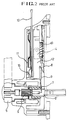
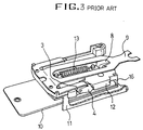
- a conventional card key locking devices (card key door lock), which have been currently commercialized, is constructed as shown in FIGS. 1 to 3.
- An actuator 12 which is installed to be movable by a predetermined distance relative to a fixed frame 11 if a card key 10 is inserted into a key slot and is then pushed. If the actuator 12 has been moved down, an impeller 8 which is formed as a unitary body with the actuator 12 pulls a coupling spring 9 in such a manner that a coupling shaft 7 couples two spline shafts 6 and 6', thus coupled with each other. At this time, if a handle grip 5 is turned, a keeper which is coupled with the spline shaft 6' operates to thereby lock or unlock a door.
- the conventional card locking device should turn the handle grip 5, without delay, to lock or unlock the door, after the card key 10 is inserted into the key slot and the force applied on the card key is in a card key insertion direction to thus move the actuator 12.
- the handle grip 5 can not be turned. Sometimes a user leave a card key in the card slot, and without extracting the key the user enters into a room.
- the present invention is directed to a card locking device that substantially obviates the problems due to limitations and disadvantages of the related arts.
- An object of the invention is to provide a card locking device where a card key removed form a key slot after the card key is inserted into a key slot and an actuator is thus moved to unlock position, the actuator is not restored to the original position without one time unlocking operation.
- Another object of the present invention is to provide a card key locking device which has a mechanism so that an unlocking coupling securely is decoupled to a locking position.
- a card locking device including: a flange provided on an end portion of the one side of the actuator; a keeper for locking the flange for preventing the actuator from returning to the original position thereof, when the actuator have been moved by insertion of a card key; and a releasing projection rotated with the rotating shaft and for pushing the keeper to a releasing position in order to return the actuator to the original position, whereby the card key moves the actuator for the rotating shaft to be coupled in operation condition, then the actuator is in the locked state by the keeper even though the card key is extracted from the card slot unless the rotating shaft finishes its rotation of a predetermined angle.
- a card locking device including: a plunger inserted in a plunger box installed on a lower end portion of the actuator and being supported by a spring; a locking protrusion formed on the fixed frame, for locking the plunger when the actuator is downward over a predetermined distance; a releasing projection rotated with the rotating shaft and for pushing the plunger to a releasing position in order to return the actuator to the original position, whereby the card key moves the actuator for the rotating shaft to be coupled in operation condition, then the actuator is in the locked state by the plunger even though the card key is extracted from the card slot unless the rotating shaft finishes its rotation of a predetermined angle.
- the present invention includes a feature that the keeper comprises a plate spring which is attached on the fixed frame, and having a locking protrusion for locking the flange of the actuator.
- the present invention includes a feature that the releasing projection is formed unitary on the rotating shaft or the releasing projection is a circular plate shape fixed to the rotating shaft, having the edge-inclined protruding and reentrant portions, the protruding portion of the releasing projection adapted to push the keeper or the plunger to be separated from the flange or the locking protrusion, and the reentrant portion thereof adapted to have the keeper or the plunger to the locking position, if the rotating shaft is rotated to the original position thereof.
- the present invention includes a further feature that a pushing portion formed on end of the actuator for pushing a coupling spring when the actuator is returning from the locked state by the keeper to the original position.
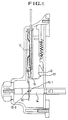
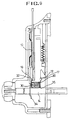
- FIGS. 4 to 6 are schematic sectional views of a card locking device constructed according to an embodiment of the present invention. An explanation of function of the components as mentioned in FIGS. 1 to 3 will be excluded in this detailed description and elements having the same function in the FIGS 1 to 3 are given the same reference numerals for the sake of brevity.
- the hook cam and restriction spring in the conventional art are not used in the present invention.
- a flange 16 is provided on the end portion of the one side of an actuator 12 and a keeper 18 is adapted to lock the flange 16 to thereby prevent the actuator 12 from returning to the original position thereof, when the actuator 12 is moved by the insertion of a card key and a rotating shaft is thus operated.
- the actuator 12 stores a cryptic code, and only when the card key inserted coincides with the cryptic code of the actuator, it can be moved by the force applied from the card key. This operation is the same as the conventional one.
- an impeller 8 is formed on the actuator 12 and is coupled with a coupling spring 9.
- the coupling spring 9 allows a coupling shaft 14-3 to be moved, thus to couple two spline shafts 14-2 and 14-4.
- the keeper 18 is fixed to the frame 11 and is made as a plate spring, as shown in FIG. 10.
- This plate spring has a locking protrusion 19 which is curved to correspond with the flange 16 formed in curved shape, so that the flange 16 of the actuator 12 is locked to the plate spring.
- the locking protrusion 19 may be formed flatly if the flange 16 is formed in flat shape contacting the locking protrusion 19.
- the keeper 18 may be used with a locking tool which presses a rotating plate having a locking protrusion by means of a spring.
- a releasing projection 20 is formed as a unitary body with the rotating shaft 14-2 as shown in FIGS. 4, 5, and 12d thereby push the keeper 18 in the opposite direction to the flange 16.
- the releasing projection 20 has a protruding portion 21 and a reentrant portion 23 on the edge portion thereof.
- the releasing projection 20' is formed in a circular plate shape as shown briefly in FIG. 6, and has a tooth-shaped hole 22 on the center portion thereof, through which it can be secured on the spline shaft 14.
- the shaft and the coupling spring, etc, are the same as those in the FIG. 4.
- the method of securing the releasing projection 20' on the spline shaft 14 is an interference fitting method or a position fixing pins 15-1 and 15-2 using method.
- FIG. 11A is a plan view of the releasing projection 20'
- FIG. 11B is a sectional view taken along the line B-B of FIG. 11A
- FIG. 11C is a sectional view taken along the line C-C of FIG. 11A.
- the releasing projection 20' forms a protruding portion 21' and a reentrant portion 23' on the edge portion thereof.
- the reentrant portion 23' is opposite to the keeper 18, the flange 16 is locked to the keeper 18, and contrarily, when the protruding portion 21' is opposite to the keeper 18, the keeper 18 is pushed and the flange 16 is then deviated from the keeper 18.
- a pushing portion 17 is formed on end of the actuator 12 for pushing a coupling spring 9 while the actuator 12 is returning from the locked state to the normal position.
- the rotating shaft 14 coupled to a handle grip 5 on one end portion thereof and on the other end portion of the rotating shaft 14 coupled to an locking shaft 14-5, which is adapted to be connected/disconnected with another locking device to lock or unlock the door.
- the rotating shaft 14 has a coupling shaft 14-3, a first spline shaft 14-2, and a second spline shaft 14-4. At the first spline shaft is formed the releasing projection 20 or 20'.
- the coupling shaft 14-3 has teeth inside thereof, and the first and second spline shaft 14-2, 14-4 have teeth outside thereof like gear.
- the impeller 8 formed on the actuator 12 has the coupling spring 9 to move the coupling shaft 14-3 to the first spline shaft 14-2 connected to the handle grip 5 through the connecting shaft 14-1, continuing coupling state with the second spline shaft 14-4 which is connected with another locking device.
- the rotating shaft 14 is provided with a rotating spring 14-6 for restoring an amount of rotation thereof. If a manual torque of the rotating shaft 14 disappears, the rotating shaft 14 can be returned to the original position by the rotating spring 14-6, after the locking or unlocking operation.
- the actuator 12 is returned to the previous position, the force of the coupling spring 9 pushing the coupling spline shaft 14-3 is lessen, so the coupling spline shaft 14-3 is returned to the previous position.
- the coupling spline shaft 14-3 is returned to normal position by forces of a pushing spring 14-7 and the coupling spring 9, the force of which is strengthened by the pushing portion 17, While the actuator returning the pushing portion pushes the coupling spring 9 back. So, the coupling spline shaft 14-3 could be returned certainly to decoupling state.
- FIGS. 7 to 9 are schematic sectional views of a card locking device constructed according to another embodiment of the present invention. An explanation of the components as mentioned in FIGS. 1 to 3 will be excluded in this detailed description for the sake of brevity.
- the coupling spline shaft, the coupling spring, etc are not drawn, but may be the same as those in the FIG. 4, or in the conventional art in FIG. 1 and FIG. 2.
- the conventional hook cam and restriction spring (as shown in FIG. 3) are not used. Instead, as shown in FIG. 7, a locking protrusion 32 are formed on the fixed frame to prevent the actuator 12 from being restored to the original position thereof. A plunger device is installed on end of the actuator 12.
- the plunger 30 is inserted in a plunger box 35, which is installed on a lower end portion of the actuator 12 and the plunger is supported by a spring 36.
- the spring 36 which is inserted into the interior of the plunger box 35, is adapted to support the force exerted to the direction of the locking protrusion 32.
- the locking protrusion 32 formed on the frame is for locking the plunger 30 when the actuator 12 is downward over a predetermined distance.
- the plunger 30 is engaged with the locking protrusion 32.
- the rotating shaft 14 comprising the coupling spline shaft, the first and second spline shaft is thus coupled and become in operation condition.
- a releasing projection 34 which is installed rotatably with the rotating shaft 14 in similar way explained in the previous embodiment. It pushes the plunger 30 to a locking releasing position to thereby restore the actuator 12 to the original position thereof.
- the releasing projection 34 has a protruding portion and a reentrant portion which respectively take the opposite shape to each other.
- the configurations of the remaining components of this embodiment are the same as the one embodiment of the present invention.
- the releasing projection 34 is adapted to push the plunger 30 to the original position thereof, if the rotating shaft 14 is rotated over a predetermined angle (for example, about 60 degrees).
- the releasing projection 34 is securely attached to the rotating shaft 14 and is in an edge-inclined circular plate shape, as shown in FIGS. 11A to 11C.
- the releasing projection 34 has a shaft hole 22 on the center portion thereof, through which it can be secured on the spline shaft.
- the releasing projection 34 forms a protruding portion 21 and a reentrant portion 23 on the edge portion thereof.
- the plunger 30 is locked to the locking protrusion 32, and contrarily, when the protruding portion 21 is opposite to the plunger 30, the plunger 30 is pushed and then deviated from the locking protrusion 32, to thereby restore the actuator 12 to the original position thereof by the restoring force of the spring.
- the card key 10 is firstly inserted and pushed in the insertion direction thereof, it is checked whether the card key coincides with the cryptic code recorded on the actuator 12. If coincides therewith, the actuator 12 is moved to lock the plunger 30 to the locking protrusion 32, such that even if the card key is extracted, the actuator 12 is kept in the locked state. In other words, the unlocked state of the actuator 12 as shown in FIG. 7 is changed to the locked state thereof as shown in FIG. 8.
- the impeller 8 formed on the actuator 12 allows the coupling spring 9 to press the coupling shaft 7 in such a manner that, as shown in FIG. 1 and 2, the spline shaft 6 having the handle grip is coupled with the spline shaft 6' connected with another locking device.
- the another locking device can be locked or unlocked.
- the handle grip is turned and the rotating shaft 14 is thus rotated over the predetermined angle (for example, about 60 degrees)
- the protruding portion 21 of the releasing projection 20 pushes the plunger 30, as shown in FIG. 9, and so, the plunger 30 is deviated from the locking protrusion 32, to thereby restore the actuator 12 to the original position thereof.
- the rotating shaft is provided with a spring for restoring an amount of rotation thereof, if the torque of the rotating shaft disappears. Thus, the rotating shaft can be restored to the original position thereof, after the locking or unlocking operation.
- the conventional card locking device should turn the handle grip, without delay, to lock or unlock the door, after a card key is inserted into a key slot and a force applied on the card key is in a card key insertion direction to thus move an actuator.
- the handle grip can not be turned.
- a card locking device can prevent, after a card key is inserted into a key slot and an actuator is moved, the actuator from being restored to an original position, even if the card key is extracted from the key slot, during a handle grip is turned and the door is thus locked or unlocked at one time, such that even under the state where the card key is extracted prior to the turning of the handle grip, the handle grip can be turned at one time, without re-insertion of the card key.
Landscapes
- Engineering & Computer Science (AREA)
- Mechanical Engineering (AREA)
- Structural Engineering (AREA)
- Lock And Its Accessories (AREA)
- Conveying Record Carriers (AREA)
Applications Claiming Priority (2)
| Application Number | Priority Date | Filing Date | Title |
|---|---|---|---|
| KR1019980008197A KR100454857B1 (ko) | 1998-03-12 | 1998-03-12 | 카드조작식쇄정장치 |
| KR9808197 | 1998-03-12 |
Publications (2)
| Publication Number | Publication Date |
|---|---|
| EP0942129A2 true EP0942129A2 (fr) | 1999-09-15 |
| EP0942129A3 EP0942129A3 (fr) | 2002-03-06 |
Family
ID=19534633
Family Applications (1)
| Application Number | Title | Priority Date | Filing Date |
|---|---|---|---|
| EP99104401A Withdrawn EP0942129A3 (fr) | 1998-03-12 | 1999-03-04 | Dispositif de verrouillage à carte-clé |
Country Status (5)
| Country | Link |
|---|---|
| US (1) | US6286345B1 (fr) |
| EP (1) | EP0942129A3 (fr) |
| KR (1) | KR100454857B1 (fr) |
| CN (1) | CN1154779C (fr) |
| TW (1) | TW425452B (fr) |
Cited By (1)
| Publication number | Priority date | Publication date | Assignee | Title |
|---|---|---|---|---|
| EP3351711A1 (fr) * | 2017-01-24 | 2018-07-25 | Tunstall Nordic AB | Dispositif de poignée de porte et porte comprenant un tel dispositif de poignée de porte |
Families Citing this family (5)
| Publication number | Priority date | Publication date | Assignee | Title |
|---|---|---|---|---|
| KR100756673B1 (ko) * | 2006-11-30 | 2007-09-07 | 주식회사 케이코하이텍 | 도어록킹장치 |
| US8210008B2 (en) * | 2008-08-08 | 2012-07-03 | Lear Corporation | Ignition module with multi-beam spring |
| JP2010095970A (ja) * | 2008-10-20 | 2010-04-30 | Elm International:Kk | 扉の解錠・施錠装置 |
| EP3927920A4 (fr) * | 2019-04-05 | 2022-12-21 | Dormakaba USA Inc. | Verrou électronique |
| CN112208769B (zh) * | 2020-09-25 | 2022-11-04 | 中国直升机设计研究所 | 一种直升机外吊挂货物挂钩收纳存放可调式锁闭机构 |
Family Cites Families (13)
| Publication number | Priority date | Publication date | Assignee | Title |
|---|---|---|---|---|
| US2732703A (en) * | 1956-01-31 | noregaard | ||
| US2593573A (en) * | 1948-01-22 | 1952-04-22 | Sargent & Co | Door latch |
| US2704934A (en) * | 1951-01-22 | 1955-03-29 | Nilsson Fabian | Key controlled tumbler lock |
| US3271983A (en) * | 1964-07-14 | 1966-09-13 | Schlage Lock Co | Magnetic locking device and method of combinating the same |
| GB1188747A (en) * | 1968-09-24 | 1970-04-22 | Walter Warren Barney | Magnet Controlled Lock. |
| DE2123850C3 (de) * | 1971-05-13 | 1981-01-08 | Noel Litvin | Flachschlüsselbetätigbares Türschloß |
| US4475364A (en) * | 1981-08-17 | 1984-10-09 | Claire D. Frank | Door-barring lock apparatus |
| US4676083A (en) * | 1986-03-07 | 1987-06-30 | Sedley Bruce S | Locking mechanism with actuator |
| WO1991002368A1 (fr) * | 1989-08-10 | 1991-02-21 | Nobuyo Sakai | Commutateur du type a carte magnetique |
| DE4001153A1 (de) * | 1990-01-17 | 1991-07-18 | Schulte Schlagbaum Ag | Magnetkartenschloss mit schluesselkarte |
| DE4002092A1 (de) * | 1990-01-25 | 1991-08-01 | Schulte Schlagbaum Ag | Schloss mit durch einschieben einer bereichsweise magnetisierten schluesselkarte freizugebender schliessfunktion |
| US5469723A (en) * | 1990-07-25 | 1995-11-28 | Litwin; Noel | Safety locks |
| KR0137881B1 (ko) * | 1994-11-17 | 1998-06-15 | 김경수 | 카드키를 이용한 시건장치 |
-
1998
- 1998-03-12 KR KR1019980008197A patent/KR100454857B1/ko not_active Expired - Fee Related
-
1999
- 1999-03-04 EP EP99104401A patent/EP0942129A3/fr not_active Withdrawn
- 1999-03-06 TW TW088103481A patent/TW425452B/zh not_active IP Right Cessation
- 1999-03-12 CN CNB991039742A patent/CN1154779C/zh not_active Expired - Fee Related
- 1999-03-12 US US09/266,946 patent/US6286345B1/en not_active Expired - Fee Related
Non-Patent Citations (1)
| Title |
|---|
| None |
Cited By (1)
| Publication number | Priority date | Publication date | Assignee | Title |
|---|---|---|---|---|
| EP3351711A1 (fr) * | 2017-01-24 | 2018-07-25 | Tunstall Nordic AB | Dispositif de poignée de porte et porte comprenant un tel dispositif de poignée de porte |
Also Published As
| Publication number | Publication date |
|---|---|
| EP0942129A3 (fr) | 2002-03-06 |
| KR100454857B1 (ko) | 2005-01-13 |
| US6286345B1 (en) | 2001-09-11 |
| KR19990074534A (ko) | 1999-10-05 |
| TW425452B (en) | 2001-03-11 |
| CN1154779C (zh) | 2004-06-23 |
| CN1238419A (zh) | 1999-12-15 |
Similar Documents
| Publication | Publication Date | Title |
|---|---|---|
| US5428978A (en) | Cylinder lock device resistible against unauthorized unlocking | |
| EP3734004B1 (fr) | Dispositif de verrouillage de porte de véhicule | |
| JPH01315569A (ja) | ロック | |
| US4389863A (en) | Combination locks | |
| US9945155B2 (en) | Cylinder lock device | |
| JPS5833679A (ja) | 自動車の防盗装置 | |
| JPS58204277A (ja) | ドアパネル用ロツクセツト | |
| GB2278874A (en) | A latch assembly for a luggage case. | |
| EP0942129A2 (fr) | Dispositif de verrouillage à carte-clé | |
| US6397646B1 (en) | Door lock | |
| US6505487B1 (en) | Locking device for use with a projection lock and method for securing an object with a projection lock | |
| US4754630A (en) | Locking device | |
| JP4411567B2 (ja) | シリンダ錠 | |
| US6269710B1 (en) | Locking device for a rotatable latching element of a selecting device | |
| JP7400513B2 (ja) | ロック装置 | |
| JPS6070283A (ja) | 金庫扉等の施錠装置 | |
| EP0162158A1 (fr) | Serrure cylindrique et clé | |
| JP3906602B2 (ja) | ラッチ機構 | |
| JPH09112108A (ja) | U字型盗難防止装置 | |
| JP3085878B2 (ja) | 両開き戸の施錠装置 | |
| JPH11141207A (ja) | ラッチ錠 | |
| JP3108633B2 (ja) | 補助錠 | |
| JPH08120982A (ja) | シリンダ錠 | |
| JP3055653B2 (ja) | 錠前装置 | |
| JP3241269B2 (ja) | ロック装置 |
Legal Events
| Date | Code | Title | Description |
|---|---|---|---|
| PUAI | Public reference made under article 153(3) epc to a published international application that has entered the european phase |
Free format text: ORIGINAL CODE: 0009012 |
|
| AK | Designated contracting states |
Kind code of ref document: A2 Designated state(s): AT BE CH CY DE DK ES FI FR GB GR IE IT LI LU MC NL PT SE |
|
| AX | Request for extension of the european patent |
Free format text: AL;LT;LV;MK;RO;SI |
|
| PUAL | Search report despatched |
Free format text: ORIGINAL CODE: 0009013 |
|
| STAA | Information on the status of an ep patent application or granted ep patent |
Free format text: STATUS: THE APPLICATION HAS BEEN WITHDRAWN |
|
| AK | Designated contracting states |
Kind code of ref document: A3 Designated state(s): AT BE CH CY DE DK ES FI FR GB GR IE IT LI LU MC NL PT SE |
|
| AX | Request for extension of the european patent |
Free format text: AL;LT;LV;MK;RO;SI |
|
| 18W | Application withdrawn |
Withdrawal date: 20020204 |