EP0942155B1 - Brennkraftmaschine mit Anti-Schaumvorrichtung - Google Patents
Brennkraftmaschine mit Anti-Schaumvorrichtung Download PDFInfo
- Publication number
- EP0942155B1 EP0942155B1 EP19990400616 EP99400616A EP0942155B1 EP 0942155 B1 EP0942155 B1 EP 0942155B1 EP 19990400616 EP19990400616 EP 19990400616 EP 99400616 A EP99400616 A EP 99400616A EP 0942155 B1 EP0942155 B1 EP 0942155B1
- Authority
- EP
- European Patent Office
- Prior art keywords
- screen
- internal combustion
- combustion engine
- oil
- forming means
- Prior art date
- Legal status (The legal status is an assumption and is not a legal conclusion. Google has not performed a legal analysis and makes no representation as to the accuracy of the status listed.)
- Expired - Lifetime
Links
Images
Classifications
-
- F—MECHANICAL ENGINEERING; LIGHTING; HEATING; WEAPONS; BLASTING
- F01—MACHINES OR ENGINES IN GENERAL; ENGINE PLANTS IN GENERAL; STEAM ENGINES
- F01M—LUBRICATING OF MACHINES OR ENGINES IN GENERAL; LUBRICATING INTERNAL COMBUSTION ENGINES; CRANKCASE VENTILATING
- F01M11/00—Component parts, details or accessories, not provided for in, or of interest apart from, groups F01M1/00 - F01M9/00
- F01M11/0004—Oilsumps
-
- F—MECHANICAL ENGINEERING; LIGHTING; HEATING; WEAPONS; BLASTING
- F01—MACHINES OR ENGINES IN GENERAL; ENGINE PLANTS IN GENERAL; STEAM ENGINES
- F01M—LUBRICATING OF MACHINES OR ENGINES IN GENERAL; LUBRICATING INTERNAL COMBUSTION ENGINES; CRANKCASE VENTILATING
- F01M11/00—Component parts, details or accessories, not provided for in, or of interest apart from, groups F01M1/00 - F01M9/00
- F01M11/06—Means for keeping lubricant level constant or for accommodating movement or position of machines or engines
- F01M11/062—Accommodating movement or position of machines or engines, e.g. dry sumps
- F01M11/064—Movement
-
- F—MECHANICAL ENGINEERING; LIGHTING; HEATING; WEAPONS; BLASTING
- F01—MACHINES OR ENGINES IN GENERAL; ENGINE PLANTS IN GENERAL; STEAM ENGINES
- F01M—LUBRICATING OF MACHINES OR ENGINES IN GENERAL; LUBRICATING INTERNAL COMBUSTION ENGINES; CRANKCASE VENTILATING
- F01M11/00—Component parts, details or accessories, not provided for in, or of interest apart from, groups F01M1/00 - F01M9/00
- F01M11/0004—Oilsumps
- F01M2011/005—Oilsumps with special anti-turbulence means, e.g. anti-foaming means or intermediate plates
-
- F—MECHANICAL ENGINEERING; LIGHTING; HEATING; WEAPONS; BLASTING
- F01—MACHINES OR ENGINES IN GENERAL; ENGINE PLANTS IN GENERAL; STEAM ENGINES
- F01M—LUBRICATING OF MACHINES OR ENGINES IN GENERAL; LUBRICATING INTERNAL COMBUSTION ENGINES; CRANKCASE VENTILATING
- F01M11/00—Component parts, details or accessories, not provided for in, or of interest apart from, groups F01M1/00 - F01M9/00
- F01M11/0004—Oilsumps
- F01M2011/0054—Fastening to the cylinder block
Definitions
- the present invention relates to the field anti-bubbling devices mounted in the oil sumps of internal combustion engines intended in particular to equip vehicles automobiles.
- An internal combustion engine includes, in general, a cylinder block receiving a cylinder head its upper end and an oil pan at its lower end.
- the lubrication circuit of such an engine conventionally comprises a pump driven by the crankshaft and which sucks the oil stored in the oil pan to send it, after filtration, through pipes suitable for moving engine parts, such as crankshaft bearings, connecting rods, pistons or camshaft, oil returns then by gravity in the oil pan.
- Document FR-A-2.650.033 discloses by example, a screen in the form of a plate in shaped sheet to protect crankshaft and crankshaft, oil contained in the crankcase oil and oil falling from the cylinder head.
- the splash screens are fixed by screws directly on the bearing caps of the crankshaft or even directly on corresponding bosses carried by the housing oil or the cylinder block.
- Such a provision has the disadvantage of complicating motor assembly and increase the cost of this last.
- the object of the present invention is to remedy this drawback by proposing an engine with an easy-to-splash prevention device mount and requiring no fixing means reported.
- the internal combustion engine according to the invention is of the type comprising a cylinder block inside which is housed a crankshaft connected to pistons by connecting rods, a oil pan and means forming an anti-splash screen to prevent the oil slick contained in the oil pan to come into contact with the crankshaft and connecting rods.
- the means forming a screen are immobilized in position simply by pinching of a plurality of holding tabs between the lower edge of the cylinder block and the corresponding edge of the oil pan.
- the legs support are housed in a groove corresponding seal interposed between the oil pan and the cylinder block.
- the positioning of the screen means is ensured by ribs extending under the legs of maintenance.
- the means forming a screen include housings intended for come to fit on bearing caps of the crankshaft to ensure prepositioning during their mounting on the cylinder block.
- the means forming a screen have fixing arms clip-on allowing their hanging on the cylinder block.
- the means forming a screen have boxes open towards the oil pan intended in particular to limit the displacement of the oil slick.
- the means forming a screen are formed by a monobloc shell obtained in molded plastic.
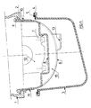
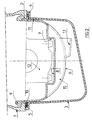
- the base of the cylinder block 1 has a peripheral edge or sidewalk 2 extending in projecting perpendicular to the side walls of the cylinder block 1 towards the inside of the latter, towards the crankshaft. against this edge peripheral 2 of cylinder block 1 comes to take press the corresponding peripheral edge 4 of the oil pan 3.
- the fixing of the oil sump 3 on the cylinder block 1 is secured by screws not figured cooperating with the peripheral edges above 2 and 4 forming a flange and counter flange.
- a type 5 seal elastomer housed in a groove formed on the edge device 4 of the oil pan 3. Dimensions of seal 5 are suitable for obtaining a rate predetermined compression when the edge device 4 comes into contact with edge 2.
- an anti-splash screen 6 is interposed between the cylinder block 1 and the oil pan 3 in order to prevent the oil in the oil pan does not come into contact with the crankshaft and crankshaft.
- This anti-splash screen 6 is produced in the form a one-piece molded plastic shell, such as a glass fiber filled polyamide. Screen 6 is shaped to wrap around the bottom of the crankshaft not shown and also the crankshaft not shown.
- the anti-splash screen 6 has a shape general semi-cylindrical corresponding substantially to the envelope curve of the trajectories crankshaft and crankshaft. The dimensions of screen 6 are adjusted to leave a clearance extremely reduced between screen and hitch mobile of the order of a few millimeters.
- Screen 6 has openings 13 arranged substantially under each of the connecting rods. These openings are oriented transversely in the direction of motor rotation, to evacuate oil splashes from the lower engine (piston, connecting rods, journals, crank pins, etc.) to the housing oil.
- Screen 6 following the shape of the hitch mobile has walls 8 facing crankshaft bearing caps. These walls 8 form transverse boxes 15 open at direction of the oil pan. The boxes 15 isolate the crankshaft peer to peer and the connecting rod of the oil slick and on the other hand they make it possible to stiffen the screen 6.
- the boxes 15 define on the other hand partitions on the underside of screen 6 which have the advantage of limiting the movement of the oil slick in the sump oil 3 and therefore planing. So the pump aspiration remains primed even in case of significant movements of the oil.
- Immobilization in position of the screen 6 is ensured by a plurality of lugs holding 10 projecting transversely relative to to the side edges of the screen 6 which come pinch between the edge 2 arranged at the base of the cylinder block 1 and the edge corresponds 4 to the housing oil 1 with interposition of the seal 5.
- the seal 5 presents a transversely opening groove suitable for receive the retaining tabs 10. It is thus possible to tighten the holding tabs 10 of the splash screen 6 without affecting the tightness of the oil pan assembly 3 on the cylinder block 1.
- cleats or ribs of positioning 11 are arranged under the legs of maintenance 10. These cleats are intended to come immobilize the side edges of the screen 6 against the corresponding side edges of the oil pan 3.
- the anti-splash screen 6 presents by elsewhere clipping arms 9 allowing the holding the screen on the cylinder block when disassembly of the oil pan 3 or during engine assembly operations on chains mounting.
- the arms 9 which are shaped for have some elasticity, whatever the material used, have at their end a protruding rim intended to come to rest on the edge 2 formed at the base of the cylinder block 1.
- the present invention applies also for engines with housing beams cap interposed between the cylinder block and the oil pan.
- the mounting of the screen is operated between the hat beam and the oil pan.
Landscapes
- Engineering & Computer Science (AREA)
- Mechanical Engineering (AREA)
- General Engineering & Computer Science (AREA)
- Lubrication Details And Ventilation Of Internal Combustion Engines (AREA)
- Cylinder Crankcases Of Internal Combustion Engines (AREA)
- Lubrication Of Internal Combustion Engines (AREA)
Claims (7)
- Verbrennungsmotor mit einem Zylinderblock (1), in dessen Inneren eine Kurbelwelle angeordnet ist, die über Pleuel mit Kolben verbunden ist, mit einer Ölwanne (3) und mit einer Anordnung (6), die eine Abschirmung bildet zur Verhinderung einer Berührung der in der Ölwanne vorhandenen Ölschicht mit der Kurbelwelle und den Pleueln, dadurch gekennzeichnet, dass die die Abschirmung bildende Anordnung (6) durch den Klemmsitz einer Vielzahl von Halteteilen (10) zwischen dem unteren Rand (2) des Zylinderblocks (1) und dem entsprechenden Rand (4) der Ölwanne (3) in ihrer Stellung gehalten wird.
- Verbrennungsmotor nach Anspruch 1, dadurch gekennzeichnet, dass die Halteteile (10) in eine entsprechende Nut in einer Dichtung (5) eingreifen, die zwischen der Ölwanne (3) und dem Zylinderblock (1) vorgesehen ist.
- Verbrennungsmotor nach einem der Ansprüche 1 bis 2, dadurch gekennzeichnet, dass die Positionierung der die Abschirmung bildenden Anordnung (6) durch Rippen (11) gewährleistet wird, die sich unterhalb der Halteteile (10) erstrecken.
- Verbrennungsmotor nach einem der Ansprüche 1 bis 3, dadurch gekennzeichnet, dass die die Abschirmung bildende Anordnung (6) Aussparungen (7) aufweist, die dazu dienen, die Lagerdeckel der Kurbelwelle zu umgeben um so eine Vorpositionierung der die Abschirmung bildenden Anordnung (6) während ihres Anbaus an den Zylinderblock zu gewährleisten.
- Verbrennungsmotor nach einem der Ansprüche 1 bis 4, dadurch gekennzeichnet, dass die die Abschirmung bildende Anordnung (6) aufsteckbare Klemmnocken (9) aufweist, die ihre Verankerung am Zylinderblock (1) ermöglichen.
- Verbrennungsmotor nach einem der Ansprüche 1 bis 5, dadurch gekennzeichnet, dass die die Abschirmung bildende Anordnung (6) zur Ölwanne (3) hin offene Fächer (15) aufweist, die insbesondere zur Begrenzung der Bewegungen der Ölschicht dienen.
- Verbrennungsmotor nach einem der Ansprüche 1 bis 6, dadurch gekennzeichnet, dass die die Abschirmung bildende Anordnung (6) aus einer Schale (6) aus gegossenem Kunststoff besteht.
Applications Claiming Priority (2)
| Application Number | Priority Date | Filing Date | Title |
|---|---|---|---|
| FR9803107 | 1998-03-13 | ||
| FR9803107A FR2776017B1 (fr) | 1998-03-13 | 1998-03-13 | Moteur a combustion interne comportant un dispositif anti-barbotage |
Publications (2)
| Publication Number | Publication Date |
|---|---|
| EP0942155A1 EP0942155A1 (de) | 1999-09-15 |
| EP0942155B1 true EP0942155B1 (de) | 2003-05-14 |
Family
ID=9524016
Family Applications (1)
| Application Number | Title | Priority Date | Filing Date |
|---|---|---|---|
| EP19990400616 Expired - Lifetime EP0942155B1 (de) | 1998-03-13 | 1999-03-12 | Brennkraftmaschine mit Anti-Schaumvorrichtung |
Country Status (4)
| Country | Link |
|---|---|
| EP (1) | EP0942155B1 (de) |
| DE (1) | DE69907786T2 (de) |
| ES (1) | ES2193669T3 (de) |
| FR (1) | FR2776017B1 (de) |
Cited By (3)
| Publication number | Priority date | Publication date | Assignee | Title |
|---|---|---|---|---|
| US6863039B2 (en) | 2001-08-24 | 2005-03-08 | Federal-Mogul Sealing Systems Bretten Gmbh & Co. Kg | Casing cover having a device for assuring sealing forces |
| DE102008060409A1 (de) * | 2008-11-28 | 2010-06-02 | Dr. Ing. H.C. F. Porsche Aktiengesellschaft | Verbrennungsmotor |
| DE102008060412B4 (de) | 2008-11-28 | 2023-03-30 | Dr. Ing. H.C. F. Porsche Aktiengesellschaft | Verbrennungsmotor |
Families Citing this family (13)
| Publication number | Priority date | Publication date | Assignee | Title |
|---|---|---|---|---|
| US6705270B1 (en) * | 2000-04-26 | 2004-03-16 | Basf Corporation | Oil pan module for internal combustion engines |
| DE10026113B4 (de) * | 2000-05-26 | 2013-07-04 | GM Global Technology Operations LLC (n. d. Ges. d. Staates Delaware) | Brennkraftmaschine mit einem zwischen Kurbelraum und Ölwanne angeordneten Ölabweisteil |
| ATE380932T1 (de) | 2001-04-10 | 2007-12-15 | Bayerische Motoren Werke Ag | Vorrichtung zur anordnung zweier einen einbauraum umschliessenden gehäuseteile einer brennkraftmaschine |
| DE10119937A1 (de) * | 2001-04-23 | 2002-11-14 | Joma Polytec Kunststofftechnik | Mehrteiliges Gehäuse sowie Ölwannenanordnung für eine Maschine |
| DE10141569B4 (de) * | 2001-08-24 | 2004-09-02 | Federal-Mogul Sealing Systems Bretten Gmbh & Co. Kg | Gehäusedeckel mit akustisch entkoppeltem Anschlag |
| FR2878893B1 (fr) * | 2004-12-07 | 2007-03-02 | Filtrauto Sa | Dispositif d'echange thermique destine a etre dispose dans un carter d'huile, carter d'huile et moteur a combustion interne comprenant un tel dispositif d'echange thermique |
| FR2878892B1 (fr) * | 2004-12-07 | 2007-03-02 | Filtrauto Sa | Carter d'huile pour moteur a combustion interne et moteur a combustion interne comprenant un tel carter d'huile |
| ATE509251T1 (de) * | 2004-12-07 | 2011-05-15 | Filtrauto | Ölwanne für brennkraftmaschine |
| JP4472569B2 (ja) * | 2005-03-29 | 2010-06-02 | 太平洋工業株式会社 | 二槽オイルパンの取付構造 |
| DE102008024265A1 (de) * | 2008-05-20 | 2009-11-26 | Ibs Filtran Kunststoff-/ Metallerzeugnisse Gmbh | Dichtung für Fluid gefüllte Behälter |
| DE102008060411B4 (de) * | 2008-11-28 | 2023-03-23 | Dr. Ing. H.C. F. Porsche Aktiengesellschaft | Verbrennungsmotor |
| FR2964146B1 (fr) * | 2010-08-27 | 2014-08-29 | Peugeot Citroen Automobiles Sa | Plaque anti emulsion permettant l'optimisation de la lubrification de liaisons mecaniques |
| CN116557105B (zh) * | 2023-05-05 | 2025-08-15 | 广西玉柴机器股份有限公司 | 一种发动机塑料油底壳机油过滤装置 |
Family Cites Families (4)
| Publication number | Priority date | Publication date | Assignee | Title |
|---|---|---|---|---|
| DE8124422U1 (de) * | 1981-08-21 | 1982-10-28 | Filterwerk Mann & Hummel Gmbh, 7140 Ludwigsburg | Vorrichtung zur sicherung des oelstandes in der oelwanne einer fahrzeug-reihenbrennkraftmaschine |
| DE3840792A1 (de) * | 1988-12-03 | 1990-06-07 | Daimler Benz Ag | Oelwanne fuer eine mehrzylindrige brennkraftmaschine |
| DE3923986C1 (de) | 1989-07-20 | 1990-01-11 | Mercedes-Benz Aktiengesellschaft, 7000 Stuttgart, De | |
| DE4204522C1 (en) * | 1992-02-15 | 1993-04-15 | Mercedes-Benz Aktiengesellschaft, 7000 Stuttgart, De | IC engine silencer with lower cover shell - has oil flow shell aperture opening into noise damping chamber |
-
1998
- 1998-03-13 FR FR9803107A patent/FR2776017B1/fr not_active Expired - Lifetime
-
1999
- 1999-03-12 EP EP19990400616 patent/EP0942155B1/de not_active Expired - Lifetime
- 1999-03-12 ES ES99400616T patent/ES2193669T3/es not_active Expired - Lifetime
- 1999-03-12 DE DE1999607786 patent/DE69907786T2/de not_active Expired - Fee Related
Cited By (4)
| Publication number | Priority date | Publication date | Assignee | Title |
|---|---|---|---|---|
| US6863039B2 (en) | 2001-08-24 | 2005-03-08 | Federal-Mogul Sealing Systems Bretten Gmbh & Co. Kg | Casing cover having a device for assuring sealing forces |
| DE102008060409A1 (de) * | 2008-11-28 | 2010-06-02 | Dr. Ing. H.C. F. Porsche Aktiengesellschaft | Verbrennungsmotor |
| DE102008060412B4 (de) | 2008-11-28 | 2023-03-30 | Dr. Ing. H.C. F. Porsche Aktiengesellschaft | Verbrennungsmotor |
| DE102008060409B4 (de) | 2008-11-28 | 2023-03-30 | Dr. Ing. H.C. F. Porsche Aktiengesellschaft | Verbrennungsmotor |
Also Published As
| Publication number | Publication date |
|---|---|
| FR2776017A1 (fr) | 1999-09-17 |
| DE69907786D1 (de) | 2003-06-18 |
| EP0942155A1 (de) | 1999-09-15 |
| DE69907786T2 (de) | 2004-03-18 |
| FR2776017B1 (fr) | 2000-05-05 |
| ES2193669T3 (es) | 2003-11-01 |
Similar Documents
| Publication | Publication Date | Title |
|---|---|---|
| EP0942155B1 (de) | Brennkraftmaschine mit Anti-Schaumvorrichtung | |
| EP0840035B1 (de) | Hydraulisches, schwingungsdämpfendes Lager | |
| EP1176336A1 (de) | Hydraulisches, schwingungsdämpfendes Lager und Kraftfahrzeug, welches mit einem solchen Lager ausgerüstet ist | |
| EP2113676B1 (de) | Schwingungsdämpfungsvorrichtung, System mit einer solchen Vorrichtung und Herstellungsverfahren | |
| FR2712042A1 (fr) | Moteur oscillant hydraulique. | |
| FR3147844A1 (fr) | Dispositif de butée de suspension à joint d’étanchéité | |
| FR2969695A1 (fr) | Carter d'huile pour moteur thermique | |
| EP0569271B1 (de) | Hydroelastisches Lager, insbesondere zur Lagerung eines Kraftfahrzeugmotors | |
| FR2923193A1 (fr) | Caisson d'auvent avec element d'etancheite | |
| EP0305246B1 (de) | Hydraulisch gedämpfte Lager | |
| EP0124433A2 (de) | Abnehmbares Gehäuse für den Nockenwellenantrieb einer Brennkraftmaschine | |
| EP0697077B1 (de) | Hydrodynamischer momentwandler, insbesondere für kraftfahrzeuge | |
| EP0378464B2 (de) | Änderungen an hydraulischen Antischwingungsvorrichtungen | |
| EP1249636A2 (de) | Hydraulisches, schwingungsdämpfendes Lager | |
| EP0571284B1 (de) | Kurbelwellendichtung für eine Verbrennungskraftmaschine, besonders für Fahrzeug | |
| EP1484480B1 (de) | Elastischer Ölwanneneinsatz | |
| FR2540582A1 (fr) | Embrayage a couronne de demarreur notamment pour vehicule automobile | |
| EP0661486A1 (de) | Thermostatventil | |
| EP0622560A1 (de) | Gegenschwingungslager mit Vorrichtung zur Begrenzung der Dehnungsbewegungen | |
| FR2849467A1 (fr) | Plaque anti-emulsion pour rigidifier les parois d'un carter d'huile de vehicule automobile | |
| FR2760042A1 (fr) | Plaque anti-emulsion d'huile, carter d'huile et moteur a combustion interne equipe d'un carter d'huile | |
| FR2910074A1 (fr) | Dispositif de demarrage pour moteur thermique, notamment de vehicule automobile | |
| EP0961048B1 (de) | Schwingungsdämpfendes Lager | |
| EP0596767A1 (de) | Hydro-elastisches Lager | |
| EP4575228A1 (de) | Gehäuse und verdichter mit einem solchen gehäuse, insbesondere für ein kraftfahrzeug |
Legal Events
| Date | Code | Title | Description |
|---|---|---|---|
| PUAI | Public reference made under article 153(3) epc to a published international application that has entered the european phase |
Free format text: ORIGINAL CODE: 0009012 |
|
| AK | Designated contracting states |
Kind code of ref document: A1 Designated state(s): DE ES GB IT |
|
| AX | Request for extension of the european patent |
Free format text: AL;LT;LV;MK;RO;SI |
|
| 17P | Request for examination filed |
Effective date: 20000224 |
|
| AKX | Designation fees paid |
Free format text: DE ES GB IT |
|
| RAP1 | Party data changed (applicant data changed or rights of an application transferred) |
Owner name: RENAULT S.A.S. |
|
| GRAH | Despatch of communication of intention to grant a patent |
Free format text: ORIGINAL CODE: EPIDOS IGRA |
|
| GRAH | Despatch of communication of intention to grant a patent |
Free format text: ORIGINAL CODE: EPIDOS IGRA |
|
| GRAA | (expected) grant |
Free format text: ORIGINAL CODE: 0009210 |
|
| AK | Designated contracting states |
Designated state(s): DE ES GB IT |
|
| PG25 | Lapsed in a contracting state [announced via postgrant information from national office to epo] |
Ref country code: IT Free format text: LAPSE BECAUSE OF FAILURE TO SUBMIT A TRANSLATION OF THE DESCRIPTION OR TO PAY THE FEE WITHIN THE PRESCRIBED TIME-LIMIT;WARNING: LAPSES OF ITALIAN PATENTS WITH EFFECTIVE DATE BEFORE 2007 MAY HAVE OCCURRED AT ANY TIME BEFORE 2007. THE CORRECT EFFECTIVE DATE MAY BE DIFFERENT FROM THE ONE RECORDED. Effective date: 20030514 Ref country code: GB Free format text: LAPSE BECAUSE OF FAILURE TO SUBMIT A TRANSLATION OF THE DESCRIPTION OR TO PAY THE FEE WITHIN THE PRESCRIBED TIME-LIMIT Effective date: 20030514 |
|
| REG | Reference to a national code |
Ref country code: GB Ref legal event code: FG4D Free format text: NOT ENGLISH |
|
| REF | Corresponds to: |
Ref document number: 69907786 Country of ref document: DE Date of ref document: 20030618 Kind code of ref document: P |
|
| REG | Reference to a national code |
Ref country code: ES Ref legal event code: FG2A Ref document number: 2193669 Country of ref document: ES Kind code of ref document: T3 |
|
| GBV | Gb: ep patent (uk) treated as always having been void in accordance with gb section 77(7)/1977 [no translation filed] |
Effective date: 20030514 |
|
| PGFP | Annual fee paid to national office [announced via postgrant information from national office to epo] |
Ref country code: DE Payment date: 20040305 Year of fee payment: 6 |
|
| PLBE | No opposition filed within time limit |
Free format text: ORIGINAL CODE: 0009261 |
|
| STAA | Information on the status of an ep patent application or granted ep patent |
Free format text: STATUS: NO OPPOSITION FILED WITHIN TIME LIMIT |
|
| PGFP | Annual fee paid to national office [announced via postgrant information from national office to epo] |
Ref country code: ES Payment date: 20040322 Year of fee payment: 6 |
|
| 26N | No opposition filed |
Effective date: 20040217 |
|
| PG25 | Lapsed in a contracting state [announced via postgrant information from national office to epo] |
Ref country code: ES Free format text: LAPSE BECAUSE OF NON-PAYMENT OF DUE FEES Effective date: 20050314 |
|
| PG25 | Lapsed in a contracting state [announced via postgrant information from national office to epo] |
Ref country code: DE Free format text: LAPSE BECAUSE OF NON-PAYMENT OF DUE FEES Effective date: 20051001 |
|
| REG | Reference to a national code |
Ref country code: ES Ref legal event code: FD2A Effective date: 20050314 |