EP0942234B1 - Elément chauffant céramique et bougie à incandescence en céramique - Google Patents
Elément chauffant céramique et bougie à incandescence en céramique Download PDFInfo
- Publication number
- EP0942234B1 EP0942234B1 EP99301658A EP99301658A EP0942234B1 EP 0942234 B1 EP0942234 B1 EP 0942234B1 EP 99301658 A EP99301658 A EP 99301658A EP 99301658 A EP99301658 A EP 99301658A EP 0942234 B1 EP0942234 B1 EP 0942234B1
- Authority
- EP
- European Patent Office
- Prior art keywords
- ceramic
- heating element
- resistance heating
- ceramic heater
- metallic sleeve
- Prior art date
- Legal status (The legal status is an assumption and is not a legal conclusion. Google has not performed a legal analysis and makes no representation as to the accuracy of the status listed.)
- Expired - Lifetime
Links
- 239000000919 ceramic Substances 0.000 title claims description 78
- 238000010438 heat treatment Methods 0.000 claims description 98
- 239000000463 material Substances 0.000 claims description 4
- 238000001746 injection moulding Methods 0.000 claims description 3
- 239000002184 metal Substances 0.000 claims description 3
- 230000005611 electricity Effects 0.000 description 6
- 230000007423 decrease Effects 0.000 description 3
- 238000005219 brazing Methods 0.000 description 1
- 230000000694 effects Effects 0.000 description 1
- 239000000945 filler Substances 0.000 description 1
- 238000005304 joining Methods 0.000 description 1
- 238000004519 manufacturing process Methods 0.000 description 1
- 239000000155 melt Substances 0.000 description 1
- 238000000034 method Methods 0.000 description 1
- 238000012986 modification Methods 0.000 description 1
- 230000004048 modification Effects 0.000 description 1
Images


Classifications
-
- H—ELECTRICITY
- H05—ELECTRIC TECHNIQUES NOT OTHERWISE PROVIDED FOR
- H05B—ELECTRIC HEATING; ELECTRIC LIGHT SOURCES NOT OTHERWISE PROVIDED FOR; CIRCUIT ARRANGEMENTS FOR ELECTRIC LIGHT SOURCES, IN GENERAL
- H05B3/00—Ohmic-resistance heating
- H05B3/10—Heating elements characterised by the composition or nature of the materials or by the arrangement of the conductor
- H05B3/12—Heating elements characterised by the composition or nature of the materials or by the arrangement of the conductor characterised by the composition or nature of the conductive material
- H05B3/14—Heating elements characterised by the composition or nature of the materials or by the arrangement of the conductor characterised by the composition or nature of the conductive material the material being non-metallic
- H05B3/141—Conductive ceramics, e.g. metal oxides, metal carbides, barium titanate, ferrites, zirconia, vitrous compounds
-
- F—MECHANICAL ENGINEERING; LIGHTING; HEATING; WEAPONS; BLASTING
- F23—COMBUSTION APPARATUS; COMBUSTION PROCESSES
- F23Q—IGNITION; EXTINGUISHING-DEVICES
- F23Q7/00—Incandescent ignition; Igniters using electrically-produced heat, e.g. lighters for cigarettes; Electrically-heated glowing plugs
- F23Q7/001—Glowing plugs for internal-combustion engines
-
- H—ELECTRICITY
- H05—ELECTRIC TECHNIQUES NOT OTHERWISE PROVIDED FOR
- H05B—ELECTRIC HEATING; ELECTRIC LIGHT SOURCES NOT OTHERWISE PROVIDED FOR; CIRCUIT ARRANGEMENTS FOR ELECTRIC LIGHT SOURCES, IN GENERAL
- H05B3/00—Ohmic-resistance heating
- H05B3/40—Heating elements having the shape of rods or tubes
- H05B3/42—Heating elements having the shape of rods or tubes non-flexible
- H05B3/48—Heating elements having the shape of rods or tubes non-flexible heating conductor embedded in insulating material
-
- H—ELECTRICITY
- H05—ELECTRIC TECHNIQUES NOT OTHERWISE PROVIDED FOR
- H05B—ELECTRIC HEATING; ELECTRIC LIGHT SOURCES NOT OTHERWISE PROVIDED FOR; CIRCUIT ARRANGEMENTS FOR ELECTRIC LIGHT SOURCES, IN GENERAL
- H05B2203/00—Aspects relating to Ohmic resistive heating covered by group H05B3/00
- H05B2203/027—Heaters specially adapted for glow plug igniters
Definitions
- the present invention relates to a ceramic heater used in a ceramic glow plug attached to a diesel engine or the like.
- a conventional ceramic heater for a ceramic glow plug attached to a diesel engine is composed of a bar-shaped insulating ceramic-heater body, a metallic sleeve fitted onto the ceramic-heater body, a resistance heating element formed of a metal or a nonmetallic material and embedded in the ceramic-heater body, and electrode leads.
- Such conventional ceramic heaters can be divided into two types, which differ according to the structure employed for establishing connection between the electrode lead of a ceramic heater and an intermediate shaft having one end fixedly held within a metallic sleeve of a ceramic glow plug.
- a temperature control resistor is interposed between the intermediate shaft of the glow plug and a lead coil connected to the electrode lead of the ceramic heater.
- the intermediate shaft of the glow plug is connected directly to the lead coil.
- the temperature control resistor allows the embedded resistance heating element to quickly increase its temperature, to thereby generate a sufficient amount of heat for starting an engine.
- the temperature control resistor must be incorporated within the metallic shell, the manufacturing cost increases, resulting in an expensive ceramic glow plug.
- the above-mentioned quick temperature increase achieved by the embedded resistant heating element is not expected. Since no temperature control resistor is used, the structure for establishing connection between the intermediate shaft and the ceramic heater is simple. However, in order to impart sufficient engine-starting performance to a ceramic glow plug utilizing such a ceramic heater, the following point must be considered in design of the ceramic heater. That is, measures for generating a sufficient amount of heat through a quick temperature increase include raising the saturation temperature of the resistance heating element greatly or employing a controller for controlling application voltage. However, when the saturation temperature of the resistance heating element is increased excessively, the durability of the ceramic heater itself decreases. When a controller for controlling application voltage is employed, the complicated structure of the controller considerably increases the overall cost of the product.
- an object of the present invention is to provide a ceramic heater which is inexpensive and has improved durability and which enables a resistance heating element to quickly raise the temperature of the heater to thereby secure good engine-starting performance.
- a ceramic heater of the present invention comprises a ceramic-heater body formed of insulating ceramics, a metallic sleeve fitted onto the ceramic-heater body, a resistance heating element embedded in the ceramic-heater body, and electrode leads.
- the length of a portion of the resistance heating element located inside the metallic sleeve is set equal to or greater than the length of a portion of the resistance heating element located outside the metallic sleeve.
- the invention is characterized in that the resistance heating element has a heating portion having a resistance per unit length which is twice that of the remaining portion or greater.
- the heating portion has a length 30 to 100% that of the portion of the resistance heating element located outside the metallic sleeve.
- the temperature of the resistance heating element of the ceramic heater can be raised quickly by means of a self-control function, without employment of a temperature control resistor or a voltage control controller and without excessive increase of the saturation voltage. Further, since the area of the heating portion can be maximized, a ceramic glow plug utilizing the ceramic heater of the present invention has good engine-starting performance and can be produced at low cost. Further, the durability of the ceramic glow plug can be improved to a sufficient degree.
- the length of the portion of the resistance heating element located inside the metallic sleeve is set to less than the length of the portion of the resistance heating element located outside the metallic sleeve, a sufficient self-control function cannot be attained. Also, if the ratio of the length of the portion of the resistance heating element located inside the metallic sleeve to the length of the portion of the resistance heating element located outside the metallic sleeve is increased to three or greater, an attained self-control function is almost the same as that obtained in the case where the ratio is two.
- the self-control function reaches a sufficient level when the length of the portion of the resistance heating element located inside the metallic sleeve is set greater than the length of the portion of the resistance heating element located outside the metallic sleeve.
- the reason for this is as follows: When a voltage is applied to the ceramic heater, the resistance heating element having a uniform resistivity generates heat uniformly at the beginning of the temperature increase. However, the heat generated at a portion of the resistance heating element located inside the metallic sleeve is radiated onto the metallic sleeve via the insulating portion and further to an engine with which the ceramic heater is in contact via the metallic sleeve.
- the speed of heating by the portion of the ceramic located inside the metallic sleeve is slower than that at the tip end portion of the ceramic located outside the metallic sleeve.
- This produces a temperature difference within the ceramic heater such that the temperature at the tip end portion of the resistance heating element outside the metallic sleeve becomes higher than that at the portion of the resistance heating element inside the metallic sleeve.
- this temperature difference results in a difference in the resistance of the heating element, so that the resistance of the heating element increases toward the tip end of the ceramic heater, and the amount of generated heat also increases toward the tip end of the ceramic heater.
- a temperature increase occurs even at the portion of the resistance heating element located inside the metallic sleeve.
- the amount of consumed energy at that portion increases, so that a temperature control function similar to that obtained through employment of a temperature control resistor is attained. Therefore, the temperature of the resistance heating element of the ceramic heater can be raised quickly without employment of a temperature control resistor or a voltage control controller and without excess increase of the saturation voltage.
- curve 1 shows temperature increase of a ceramic heater in which the ratio of the length of a portion of the resistance heating element located inside a metallic sleeve to the length of a portion of the resistance heating element located outside the metallic sleeve is greater than 1
- curve 2 shows temperature increase of a ceramic heater in which the length ratio is less than 1.
- the heating portion of the resistance heating element located outside the metallic sleeve preferably has a maximum area within the range that allows rapid temperature increase at the heating portion. If the length of the heating portion is not greater than 30% the length of the portion of the resistance heating element located outside the metallic sleeve, the heat generating portion can raise the temperature locally, but heat is generated in a small region in a concentrated manner, resulting in degraded durability under application of electricity. Further, since the area of the heat generating portion becomes small, the engine-starting performance deteriorates.
- the length of the heating portion is not less than 100% the length of the portion of the resistance heating element located outside the metallic sleeve, heat is generated even within the metallic sleeve fitted onto the ceramic-heater body. Accordingly, a brazing filler material joining together the ceramic-heater body and the metallic sleeve fitted thereon melts and disappears, resulting in possible breakage of the ceramic heater itself.
- the length of the heating portion of the resistance heating element is set to 30 to 100% the length of the portion of the resistance heating element located outside the metallic sleeve. Through this design, the area of the heating portion can be maximized in order to ensure that a ceramic glow plug utilizing the ceramic heater of the present invention has good engine-starting performance.
- a ceramic heater 1 is composed of a bar-shaped insulating ceramic-heater body 2, a metallic sleeve 4 fitted onto the ceramic-heater body 2, a resistance heating element 6 formed of a metal or a nonmetallic material and embedded in the ceramic-heater body 2, and electrode leads 8.
- the ceramic heater 1 is manufactured by, for example, the method described in U.S. patent application No. 08/826,144, 08/827,160, or 09/060,474.
- the length of a portion 6' of the resistance heating element 6 located inside the metallic sleeve 4 is set equal to or greater than the length of a portion 6" of the resistance heating element 6 located outside the metallic sleeve 4.
- the resistance heating element 6 has a heating portion 7 which has a resistance per unit length which is twice that of the remaining portion or greater.
- the heating portion 7 has a length 30 to 100% the length of the portion 6" of the resistance heating element 6 located outside the metallic sleeve 4.
- the ceramic heater 1 has the structure as described above. Since the length of the portion 6' of the resistance heating element 6 located inside the metallic sleeve 4 is set equal to or greater than the length of the portion 6" of the resistance heating element 6 located outside the metallic sleeve 4, a sufficient self-control function is attained. When a voltage is applied to the ceramic heater 1 of the present embodiment, a temperature increase arises at the heating portion 7 of the portion 6" of the resistance heating element 6 located outside the metallic sleeve 4, and when the temperature increase enters a second half period, a temperature increase arises at the portion 6' of the resistance heating element 6 located inside the metallic sleeve 4.
- the temperature of the resistance heating element 6 of the ceramic heater 1 can be increased quickly without employment of a temperature control resistor or a voltage control controller and without excess increase of the saturation voltage.
- the heating portion 7 of the portion 6" of the resistance heating element 6 located outside the metallic sleeve 4 preferably has a maximum area within the range that allows rapid temperature increase at the heating portion 7. Therefore, the length of the heating portion 7 is set to 30 to 100% the length of the portion 6" of the resistance heating element 6 located outside the metallic sleeve 4. Through this design, the area of the heating portion 7 can be maximized in order to ensure that a ceramic glow plug utilizing the ceramic heater of the present embodiment has good engine-starting performance.
- the table of FIG. 3 shows the test results.
- the overall length of the resistance heating element 6 embedded in the ceramic-heater body 2 of the ceramic heater 1 is taken as A, and the length of a portion 6' of the resistance heating element 6 located inside the metallic sleeve 4 is taken as B. Further, the length of a portion 6" of the resistance heating element 6 located outside the metallic sleeve 4 is taken as C, and the length of the heating portion 7 of the resistance heating element 6 is taken as D.
- the ratio B/C represents the ratio of the length of the portion 6' of the resistance'heating element 4 located inside the metallic sleeve 4 to the length of the portion 6" of the resistance heating element 6 located outside the metallic sleeve 4
- the ratio D/C represents the ratio of the length of the heating portion 7 to the length of the portion 6" of the resistance heating element 6 located outside the metallic sleeve 4.
- the length of the portion 6" of the resistance heating element 6 located outside the metallic sleeve 4 relates to the resistance of the resistance heating element 6 embedded in the ceramic-heater body 2 of the ceramic heater 1.
- the length of a portion 6" also changes depending on the kind of engine or the like.
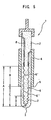
- the above-described dimensional relationships can be applied to a ceramic heater which has a resistance heating element formed through printing (shown in FIGS. 4A and 4B), as well as to a ceramic heater which has a resistance heating element formed through injection molding (shown in FIG. 5).
Landscapes
- Engineering & Computer Science (AREA)
- Chemical & Material Sciences (AREA)
- Combustion & Propulsion (AREA)
- Mechanical Engineering (AREA)
- General Engineering & Computer Science (AREA)
- Ceramic Engineering (AREA)
- Resistance Heating (AREA)
Claims (7)
- Elément chauffant en céramique, comprenant : un corps (2) d'élément chauffant en céramique constitué de céramique isolante ; un manchon métallique (24) placé sur le corps d'élément chauffant en céramique ; un élément chauffant à effet Joule (6) noyé dans le corps (2) d'élément chauffant en céramique ; et des conducteurs formant électrodes (8),
la longueur d'une partie (6') de l'élément chauffant (6) à effet Joule située à l'intérieur du manchon métallique (4) étant établie égale ou supérieure à la longueur d'une partie (6") de l'élément chauffant (6) à effet Joule située à l'extérieur du manchon métallique (4) ; et
caractérisé en ce que l'élément chauffant (6) à effet Joule comporte une partie chauffante (7) ayant une résistance par unité de longueur égale ou supérieure au double de celle de la partie restante. - Elément chauffant en céramique selon la revendication 1, dans lequel la partie chauffante (7) a une longueur de 30 à 100 % de celle de la partie (6") de l'élément chauffant (6) à effet Joule située à l'extérieur du manchon métallique (4).
- Elément chauffant en céramique selon la revendication 1 ou 2, dans lequel l'élément chauffant (6) à effet Joule est en métal.
- Elément chauffant en céramique selon la revendication 1 ou 2, dans lequel l'élément chauffant (6) à effet Joule est en matière non métallique.
- Elément chauffant en céramique selon l'une quelconque des revendications précédentes, dans lequel l'élément chauffant (6) à effet Joule est formé par impression.
- Elément chauffant en céramique selon l'une quelconque des revendications 1 à 4, dans lequel l'élément chauffant (6) à effet Joule est formé par moulage par injection.
- Bougie de préchauffage en céramique comprenant un élément chauffant en céramique selon l'une quelconque des revendications 1 à 6.
Applications Claiming Priority (2)
| Application Number | Priority Date | Filing Date | Title |
|---|---|---|---|
| JP7505298 | 1998-03-10 | ||
| JP10075052A JPH11257659A (ja) | 1998-03-10 | 1998-03-10 | セラミックヒータ及びセラミックグロープラグ |
Publications (3)
| Publication Number | Publication Date |
|---|---|
| EP0942234A2 EP0942234A2 (fr) | 1999-09-15 |
| EP0942234A3 EP0942234A3 (fr) | 2002-10-09 |
| EP0942234B1 true EP0942234B1 (fr) | 2004-10-20 |
Family
ID=13565055
Family Applications (1)
| Application Number | Title | Priority Date | Filing Date |
|---|---|---|---|
| EP99301658A Expired - Lifetime EP0942234B1 (fr) | 1998-03-10 | 1999-03-05 | Elément chauffant céramique et bougie à incandescence en céramique |
Country Status (5)
| Country | Link |
|---|---|
| US (1) | US6111223A (fr) |
| EP (1) | EP0942234B1 (fr) |
| JP (1) | JPH11257659A (fr) |
| BR (1) | BR9900679A (fr) |
| DE (1) | DE69921218T2 (fr) |
Families Citing this family (19)
| Publication number | Priority date | Publication date | Assignee | Title |
|---|---|---|---|---|
| JP3908864B2 (ja) * | 1998-09-11 | 2007-04-25 | 日本特殊陶業株式会社 | セラミックヒータ |
| DE19930334C2 (de) * | 1999-07-02 | 2003-07-31 | Beru Ag | Keramischer Heizstab und diesen enthaltende Glühkerze und Verfahren zu dessen Herstellung |
| DE10052178C1 (de) * | 2000-10-20 | 2002-05-29 | Siemens Ag | Elektrischer Widerstand |
| DE10053327C2 (de) * | 2000-10-27 | 2003-04-10 | Bosch Gmbh Robert | Stiftheizer |
| US6610964B2 (en) | 2001-03-08 | 2003-08-26 | Stephen J. Radmacher | Multi-layer ceramic heater |
| US6396028B1 (en) | 2001-03-08 | 2002-05-28 | Stephen J. Radmacher | Multi-layer ceramic heater |
| JP4294232B2 (ja) * | 2001-05-02 | 2009-07-08 | 日本特殊陶業株式会社 | セラミックヒータ及びそれを用いたグロープラグ |
| DE60231164D1 (de) * | 2001-05-02 | 2009-04-02 | Ngk Spark Plug Co | Keramisches Heizelement, Glühkerze mit solchem Heizelement und Herstellungsverfahren |
| JP2003148731A (ja) * | 2001-08-28 | 2003-05-21 | Ngk Spark Plug Co Ltd | グロープラグ |
| US20030085214A1 (en) * | 2001-11-07 | 2003-05-08 | University Of Colorado At Boulder | Micro-glow plug and method of making same field of the invention |
| JP3886449B2 (ja) * | 2002-12-26 | 2007-02-28 | 日本特殊陶業株式会社 | グロープラグ及びグロープラグの取付け構造 |
| WO2005060311A1 (fr) | 2003-11-25 | 2005-06-30 | Kyocera Corporation | Dispositif chauffant en ceramique et procede de fabrication |
| DE102005030208A1 (de) * | 2005-06-29 | 2007-01-25 | Robert Bosch Gmbh | Glühstiftkerze |
| WO2009057597A1 (fr) * | 2007-10-29 | 2009-05-07 | Kyocera Corporation | Elément chauffant en céramique et bougie de préchauffage équipée de l'élément chauffant |
| EP2257119B1 (fr) * | 2008-02-20 | 2018-04-04 | Ngk Spark Plug Co., Ltd. | Élément chauffant en céramique et bougie de préchauffage |
| US20100078421A1 (en) * | 2008-10-01 | 2010-04-01 | Federal-Mogul Italy Sr1 | Glow plug adn heater assembly therefor with an improved connection between a central electrode and a heater probe of the heater assembly |
| US20120006809A1 (en) * | 2010-06-23 | 2012-01-12 | Colorado State University Research Foundation | Sublimation crucible with embedded heater element |
| JP5726311B2 (ja) * | 2011-08-29 | 2015-05-27 | 京セラ株式会社 | ヒータおよびこれを備えたグロープラグ |
| US10514017B2 (en) | 2017-03-21 | 2019-12-24 | Pratt & Whitney Canada Corp. | Internal combustion engine with igniter cooling sleeve |
Family Cites Families (14)
| Publication number | Priority date | Publication date | Assignee | Title |
|---|---|---|---|---|
| US4346679A (en) * | 1979-02-01 | 1982-08-31 | Lucas Industries Limited | Starting aids for internal combustion engines |
| JPS59231321A (ja) * | 1983-06-13 | 1984-12-26 | Ngk Spark Plug Co Ltd | 自己制御型グロ−プラグ |
| JPS6029517A (ja) * | 1983-07-29 | 1985-02-14 | Ngk Spark Plug Co Ltd | セラミツクグロ−プラグ |
| US4650963A (en) * | 1983-09-21 | 1987-03-17 | Ngk Spark Plug Co., Ltd. | Ceramic glow plug |
| JPS618526A (ja) * | 1984-06-25 | 1986-01-16 | Ngk Spark Plug Co Ltd | セラミツクグロ−プラグ |
| DE3802233A1 (de) * | 1987-01-22 | 1988-08-04 | Jidosha Kiki Co | Gluehkerze fuer einen dieselmotor |
| JPH01263420A (ja) * | 1988-04-13 | 1989-10-19 | Ngk Spark Plug Co Ltd | 二線式セラミックグロープラグ及びその製造方法 |
| JPH04143518A (ja) * | 1990-10-04 | 1992-05-18 | Ngk Spark Plug Co Ltd | 自己制御型セラミックグロープラグ |
| JPH04263702A (ja) * | 1991-02-18 | 1992-09-18 | Hino Motors Ltd | グロープラグ |
| JPH04288410A (ja) * | 1991-03-15 | 1992-10-13 | Hino Motors Ltd | メタノールエンジン用グロープラグ |
| US5367994A (en) * | 1993-10-15 | 1994-11-29 | Detroit Diesel Corporation | Method of operating a diesel engine utilizing a continuously powered glow plug |
| JPH09190874A (ja) * | 1995-12-29 | 1997-07-22 | Ngk Spark Plug Co Ltd | セラミックヒータ |
| JPH09303774A (ja) * | 1996-05-09 | 1997-11-28 | Zexel Corp | グロープラグ |
| US5676100A (en) * | 1996-08-30 | 1997-10-14 | Caterpillar Inc. | Glow plug assembly |
-
1998
- 1998-03-10 JP JP10075052A patent/JPH11257659A/ja active Pending
-
1999
- 1999-03-03 US US09/261,650 patent/US6111223A/en not_active Expired - Lifetime
- 1999-03-05 EP EP99301658A patent/EP0942234B1/fr not_active Expired - Lifetime
- 1999-03-05 DE DE69921218T patent/DE69921218T2/de not_active Expired - Lifetime
- 1999-03-09 BR BR9900679-0A patent/BR9900679A/pt not_active IP Right Cessation
Also Published As
| Publication number | Publication date |
|---|---|
| EP0942234A2 (fr) | 1999-09-15 |
| JPH11257659A (ja) | 1999-09-21 |
| DE69921218D1 (de) | 2004-11-25 |
| EP0942234A3 (fr) | 2002-10-09 |
| BR9900679A (pt) | 2000-02-29 |
| DE69921218T2 (de) | 2006-03-09 |
| US6111223A (en) | 2000-08-29 |
Similar Documents
| Publication | Publication Date | Title |
|---|---|---|
| EP0942234B1 (fr) | Elément chauffant céramique et bougie à incandescence en céramique | |
| US4682008A (en) | Self-temperature control type glow plug | |
| JPS62731A (ja) | デイ−ゼルエンジン用グロ−プラグ | |
| JP2745225B2 (ja) | デイーゼルエンジン用グロープラグ | |
| US5132516A (en) | Glow plug having self-temperature control function | |
| JP2570481Y2 (ja) | 自己温度制御型グロープラグ | |
| JPH07293417A (ja) | 自己温度制御形グロープラグ | |
| US20060102611A1 (en) | Glowplug with greatly shortened control coil | |
| JP3351573B2 (ja) | セラミック発熱体 | |
| JPH0311577Y2 (fr) | ||
| JPS6350606Y2 (fr) | ||
| JPS61217623A (ja) | 自己温度制御型グロ−プラグ | |
| JPH0155369B2 (fr) | ||
| JPS6360289B2 (fr) | ||
| JPH0450488B2 (fr) | ||
| JPH031014A (ja) | 自己制御型セラミックグロープラグ | |
| JPS6144221A (ja) | デイ−ゼルエンジン用グロ−プラグ | |
| JPH0228044B2 (fr) | ||
| JPH0228045B2 (fr) | ||
| JPS62194117A (ja) | デイ−ゼルエンジン等に用いるシ−ズグロ−プラグ | |
| JPH0311576Y2 (fr) | ||
| JPH0419330Y2 (fr) | ||
| JPS59231322A (ja) | 自己制御型グロ−プラグ | |
| JP2002106843A (ja) | グロープラグ | |
| EP0902236B1 (fr) | Bougie à incandescence |
Legal Events
| Date | Code | Title | Description |
|---|---|---|---|
| PUAI | Public reference made under article 153(3) epc to a published international application that has entered the european phase |
Free format text: ORIGINAL CODE: 0009012 |
|
| AK | Designated contracting states |
Kind code of ref document: A2 Designated state(s): AT BE CH CY DE DK ES FI FR GB GR IE IT LI LU MC NL PT SE |
|
| AX | Request for extension of the european patent |
Free format text: AL;LT;LV;MK;RO;SI |
|
| PUAL | Search report despatched |
Free format text: ORIGINAL CODE: 0009013 |
|
| AK | Designated contracting states |
Kind code of ref document: A3 Designated state(s): AT BE CH CY DE DK ES FI FR GB GR IE IT LI LU MC NL PT SE |
|
| AX | Request for extension of the european patent |
Free format text: AL;LT;LV;MK;RO;SI |
|
| 17P | Request for examination filed |
Effective date: 20030317 |
|
| AKX | Designation fees paid |
Designated state(s): DE FR GB IT |
|
| GRAP | Despatch of communication of intention to grant a patent |
Free format text: ORIGINAL CODE: EPIDOSNIGR1 |
|
| GRAS | Grant fee paid |
Free format text: ORIGINAL CODE: EPIDOSNIGR3 |
|
| GRAA | (expected) grant |
Free format text: ORIGINAL CODE: 0009210 |
|
| AK | Designated contracting states |
Kind code of ref document: B1 Designated state(s): DE FR GB IT |
|
| REG | Reference to a national code |
Ref country code: GB Ref legal event code: FG4D |
|
| REF | Corresponds to: |
Ref document number: 69921218 Country of ref document: DE Date of ref document: 20041125 Kind code of ref document: P |
|
| PG25 | Lapsed in a contracting state [announced via postgrant information from national office to epo] |
Ref country code: GB Free format text: LAPSE BECAUSE OF NON-PAYMENT OF DUE FEES Effective date: 20050305 |
|
| PLBE | No opposition filed within time limit |
Free format text: ORIGINAL CODE: 0009261 |
|
| STAA | Information on the status of an ep patent application or granted ep patent |
Free format text: STATUS: NO OPPOSITION FILED WITHIN TIME LIMIT |
|
| ET | Fr: translation filed | ||
| 26N | No opposition filed |
Effective date: 20050721 |
|
| GBPC | Gb: european patent ceased through non-payment of renewal fee |
Effective date: 20050305 |
|
| PGFP | Annual fee paid to national office [announced via postgrant information from national office to epo] |
Ref country code: IT Payment date: 20100320 Year of fee payment: 12 |
|
| PG25 | Lapsed in a contracting state [announced via postgrant information from national office to epo] |
Ref country code: IT Free format text: LAPSE BECAUSE OF NON-PAYMENT OF DUE FEES Effective date: 20110305 |
|
| REG | Reference to a national code |
Ref country code: FR Ref legal event code: PLFP Year of fee payment: 18 |
|
| PGFP | Annual fee paid to national office [announced via postgrant information from national office to epo] |
Ref country code: DE Payment date: 20160302 Year of fee payment: 18 |
|
| PGFP | Annual fee paid to national office [announced via postgrant information from national office to epo] |
Ref country code: FR Payment date: 20160208 Year of fee payment: 18 |
|
| REG | Reference to a national code |
Ref country code: DE Ref legal event code: R119 Ref document number: 69921218 Country of ref document: DE |
|
| REG | Reference to a national code |
Ref country code: FR Ref legal event code: ST Effective date: 20171130 |
|
| PG25 | Lapsed in a contracting state [announced via postgrant information from national office to epo] |
Ref country code: DE Free format text: LAPSE BECAUSE OF NON-PAYMENT OF DUE FEES Effective date: 20171003 Ref country code: FR Free format text: LAPSE BECAUSE OF NON-PAYMENT OF DUE FEES Effective date: 20170331 |