EP0942273A2 - Verfahren zur Ermittlung des Unwuchtausgleichs bei elastischen Rotoren - Google Patents
Verfahren zur Ermittlung des Unwuchtausgleichs bei elastischen Rotoren Download PDFInfo
- Publication number
- EP0942273A2 EP0942273A2 EP99104797A EP99104797A EP0942273A2 EP 0942273 A2 EP0942273 A2 EP 0942273A2 EP 99104797 A EP99104797 A EP 99104797A EP 99104797 A EP99104797 A EP 99104797A EP 0942273 A2 EP0942273 A2 EP 0942273A2
- Authority
- EP
- European Patent Office
- Prior art keywords
- force
- rotor
- excitation
- compensation
- influence
- Prior art date
- Legal status (The legal status is an assumption and is not a legal conclusion. Google has not performed a legal analysis and makes no representation as to the accuracy of the status listed.)
- Granted
Links
Images

Classifications
-
- G—PHYSICS
- G01—MEASURING; TESTING
- G01M—TESTING STATIC OR DYNAMIC BALANCE OF MACHINES OR STRUCTURES; TESTING OF STRUCTURES OR APPARATUS, NOT OTHERWISE PROVIDED FOR
- G01M1/00—Testing static or dynamic balance of machines or structures
- G01M1/14—Determining imbalance
- G01M1/16—Determining imbalance by oscillating or rotating the body to be tested
- G01M1/24—Performing balancing on elastic shafts, e.g. for crankshafts
-
- G—PHYSICS
- G01—MEASURING; TESTING
- G01M—TESTING STATIC OR DYNAMIC BALANCE OF MACHINES OR STRUCTURES; TESTING OF STRUCTURES OR APPARATUS, NOT OTHERWISE PROVIDED FOR
- G01M1/00—Testing static or dynamic balance of machines or structures
- G01M1/14—Determining imbalance
- G01M1/16—Determining imbalance by oscillating or rotating the body to be tested
- G01M1/22—Determining imbalance by oscillating or rotating the body to be tested and converting vibrations due to imbalance into electric variables
Definitions
- the invention relates to a method for determining the unbalance compensation with elastic rotors according to claim 1.
- a rotor or a shaft has an infinite number critical speeds. To the vibration behavior at a To judge certain speed, only those are critical Speeds taken into account, their associated deflection forms or disrupt eigenmodes. In practice it is enough with many types of rotors mostly to consider a critical speed, which excites a rotor for shaft elasticity. In In certain cases, however, it may also be necessary to have several to consider critical speed ranges. An easy one roller-shaped rotor will be close to the first critical Speed u-shaped, close to the second s-shaped and bend near the third w-shaped. The critical ones Deflection shapes associated with speeds will also be Eigen modes of the rotor called.
- Elastic deflections must be reckoned with all the more, the higher the operating speed. Aim of balancing it is therefore the rigid body forces in the entire permissible speed range and the wave elastic deflection and with it reduce associated forces to a tolerable level. In practice, several balancing methods are known take such a wave-elastic behavior of rotors into account.
- Another balancing method for is known from DE 41 33 787 A1 elastic rotors known that without test weight runs the for Compensation of the rigid body unbalance and the wave elastic Deflections of the rotor required compensating masses determined.
- an unbalance measurement run at a speed at which the Rotor shows rigid body behavior is first at least one Unbalance value determined.
- the invention has for its object a method for Determination of the unbalance compensation for elastic rotors create that without test weight runs and essentially without Use of separately determined rotor and bearing specific Characteristics of a quick elimination of rotor imbalance ensures elastic rotors.
- the invention is based on the finding that by means of force excitation of the rotor in several compensation planes Imbalance compensation completely required influence coefficients can be determined. By means of a primary unbalance run and the determined and transformed with regard to unbalance Influence coefficients can be easily searched for Determine compensation unbalance.
- the unbalance measuring device shown schematically in FIG. 1 has a first bearing device 1 and a second bearing device 2 for the rotor 10, for example as conventional swing bridge mounting of a force or displacement measuring Balancing machine are trained. These are against stationary parts of the balancing machine are supported so that they can vibrate, which is indicated by the spring / mass symbols 3, 4 and 5, 6.
- Force-balancing machines are made in a known manner the detection of vibrations via force transducers, with displacement sensors Balancing machines via vibration path or vibration speed sensors.
- the transducers are in Fig. 1 with the Reference numerals 7 and 8 marked and are with respect to their Measuring direction horizontal and perpendicular to the axis of rotation arranged.
- a pickup 12 for scanning is also provided the speed of the rotor 10.
- A is not shown Drive for the rotary movement of the rotor 10, which in known
- be connected to one of the rotor pins can or can be designed as a belt drive.
- the drive can be equipped with a separate speed sensor the speed measuring device included.
- the drive is designed that fixed speeds can also be specified.
- the rotor 10 has two rotor pins and is largely symmetrical.
- only the wave-elastic behavior of the first rotor shape should be taken into account and compensated; therefore only three compensation levels WE 1 , WE 2 and WE 3 are provided.
- n + 2 compensation levels must be provided to take into account n eigenmodes, whereby in practice the first three eigenmodes are taken into account, since the unbalance effects of other eigenmodes can be neglected in practice.
- the hammer 11 is provided with a device with which the time-dependent course of the excitation force is detected, so that one excitation force spectrum per compensation or balancing plane WE 1 , WE 2 and WE 3 can be formed.
- the sensor 7, 8 on the respective bearing device 1, 2 provides a time-dependent bearing force curve in this bearing or measuring level ME 1 , ME 2 , so that one force spectrum per bearing level and per excitation, in the example three complex spectra per bearing level due to the excitations can be formed in the three balancing levels WE 1 , WE 2 and WE 3 .
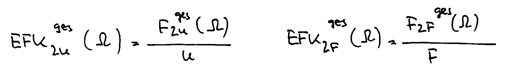
- the measurement-determined EFK F curves for force excitation must be converted or transformed differently to EFK U curves for unbalance excitation.
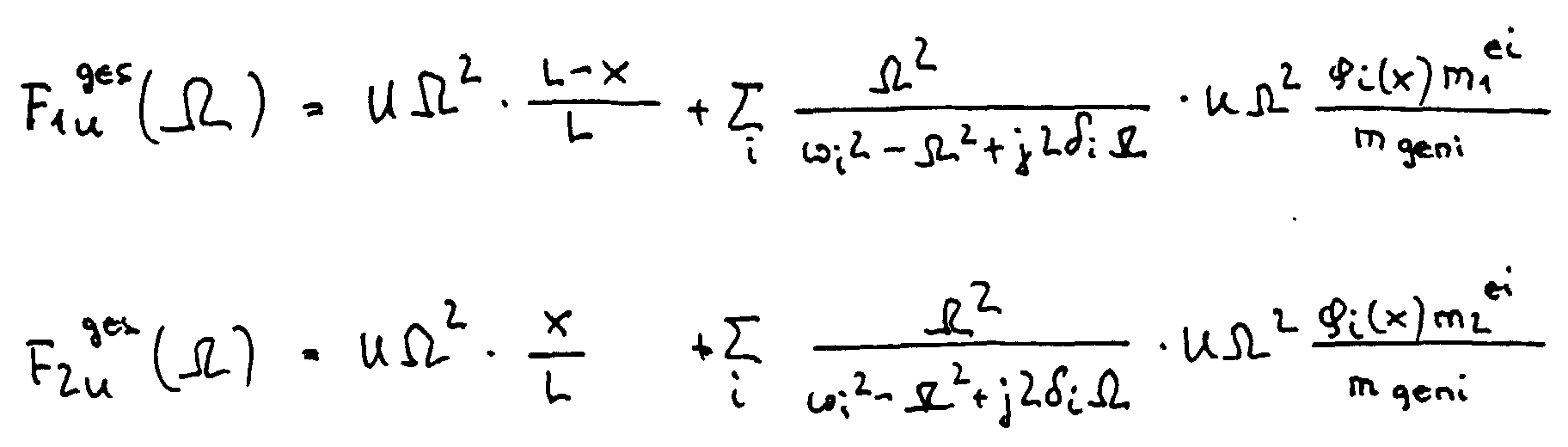
- the force-influence coefficients EFK F or ⁇ ij F which result from the force excitation, are in the case of the same conditions at standstill and during rotation as follows in relation to the unbalance influence coefficients EFK U or ⁇ ij U : with ⁇ angular frequency of the rotor.
- the ⁇ i and ⁇ i values from the force excitation at standstill can be replaced by the natural angular frequencies ⁇ i determined in the run-up or unbalance measurement run and modal decay constants ⁇ i , which can also be identified again, for example, by modal analysis.
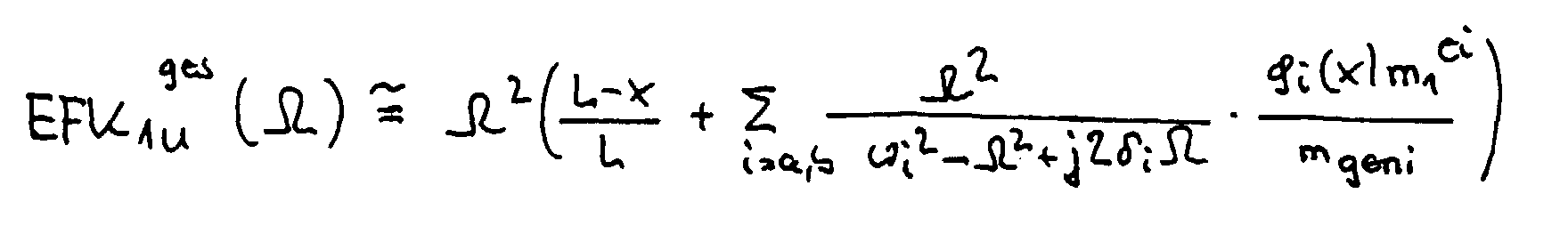
- the equation on page 8 would be as follows wherein the first term ges in the bracket from the EFK F ( ⁇ ) curve derived by power excitation at a standstill, the last term in the second term of the bracket is obtained by means of modal analysis for motor excitation at a standstill, and ⁇ i, ⁇ i are values accrued during startup or unbalance measurement.
Landscapes
- Physics & Mathematics (AREA)
- General Physics & Mathematics (AREA)
- Testing Of Balance (AREA)
Abstract
Description
- Fig. 1
- eine schematische perspektivische Darstellung einer Unwuchtmeßeinrichtung,
- Fig. 2
- eine prinzipielle Darstellung des Einflußkoeffizientenverlaufs im Stillstand und bei Rotation.
- U
- = Unwucht in der Unwuchtebene
- x
- = Abstand der Unwuchtebene von der linken Lagerebene ME1
- L
- = Abstand der beiden Lagerebenen
- ϕ(x)
- = i.te Eigenform
- ωi
- = i.te Eigenkreisfrequenz
- δi
- = modale Abklingkonstante der i.ten Eigenform
- mgeni
- = modale Systemmasse der i.ten Eigenform
- m1/2ei
- = auf die linke/rechte Lagereinrichtung bezogene eigenformspezifische Ersatzmasse der i.ten Eigenform
- Ω
- = Kreisfrequenz


- j =
- 1,2 die Meßebenen bzw. Lagerebenenanzahl ist; im Beispiel j = 2
- i =
- 1,2 3 die Wuchtebene bzw. Ausgleichsebenenanzahl ist, im Beispiel i = 3
- F
- die Kraft-Einflußkoeffizienten kennzeichnet
- n =
- Rotordrehzahl


Claims (9)
- Verfahren zur Ermittlung des Unwuchtausgleichs bei elastischen Rotoren, bei dem der Rotor in zumindest zwei Lagereinrichtungen drehbar gelagert wird, der Rotor in jeder vorgesehenen Ausgleichsebene vorzugsweise mechanisch beispielsweise durch Hammerschlag quer zur Achsrichtung krafterregt wird, das Kraftspektrum der Erregerkraft ermittelt wird, das dadurch induzierte Schwingungsverhalten des Rotors vorzugsweise in seinen Lagerebenen als Antwortspektrum in Form eines Kraft- oder Schwingungsspektrums erfaßt wird, Einflußkoeffizienten aus dem Verhältnis von Antwortspektren zu den Erregerkraftspektren hergeleitet werden, in einem Meßlauf Rotordrehzahlen zugeordnete Kraft- oder Schwingungssignale vorzugsweise in den Lagerebenen gemessen werden und unter Heranziehung der Einflußkoeffizienten und der bei der Rotation gemessenen Kraft- oder Schwingungssignale die Kompensationsunwuchten ermittelt werden.
- Verfahren nach Anspruch 1, dadurch gekennzeichnet, daß die Lösung des unter Heranziehung der Einflußkoeffizienten und der aus den Kraft- oder Schwingungssignalen des Meßlaufs abgeleiteten Größen gebildeten Gleichungssystems nach der Methode der kleinsten Fehlerquadratsumme erfolgt.
- Verfahren nach Anspruch 1 oder Anspruch 2, dadurch gekennzeichnet, daß in dem Drehzahlbereich, in dem der Rotor als starr zu betrachten ist und in zumindest einem Drehzahlbereich, bei dem der Rotor elastische Auslenkungen zeigt, gemessen wird.
- Verfahren nach Anspruch 3, dadurch gekennzeichnet, daß zur Erfassung von n Eigenformen in n-Drehzahlbereichen, in denen sich elastisches Verhalten des Rotors zeigt, gemessen wird.
- Verfahren zur Ermittlung der Einflußkoeffizienten zum Auswuchten elastischer Rotoren, bei dem der Rotor in zumindest zwei Lagereinrichtungen drehbar gelagert wird, der Rotor in jeder vorgesehenen Ausgleichsebene vorzugsweise mechanisch beispielsweise durch Hammerschlag quer zur Achsrichtung krafterregt wird, das Kraftspektrum der Erregerkraft ermittelt wird, das dadurch induzierte Schwingungsverhalten des Rotors vorzugsweise in seinen Lagerebenen als Antwortspektrum in Form eines Kraft- oder Schwingungsspektrums erfaßt wird und Einflußkoeffizienten aus dem Verhältnis von meßtechnisch erfaßten Antwortspektren zu den meßtechnisch erfaßten Erregerkraftspektren hergeleitet und transformiert werden zu Einflußkoeffizienten bei Unwuchtanregung.
- Verfahren nach einem der vorhergehenden Ansprüche, dadurch gekennzeichnet, daß Veränderungen des Einflusses der modalen Beiträge auf den Verlauf der Einflußkoeffizienten berücksichtigt werden.
- Verfahren nach Anspruch 6, dadurch gekennzeichnet, daß mittels Modalanalyse der Einfluß der modalen Beiträge ermittelt wird.
- Verfahren nach einem der vorhergehenden Ansprüche, dadurch gekennzeichnet, daß die Krafterregung in Meßrichtung der Kraft- oder Schwingungsaufnehmer erfolgt.
- Verfahren nach einem oder mehreren der vorhergehenden Ansprüche, dadurch gekennzeichnet, daß die Krafterregung bei rotierendem Rotor vorgenommen wird.
Applications Claiming Priority (2)
| Application Number | Priority Date | Filing Date | Title |
|---|---|---|---|
| DE19811101A DE19811101A1 (de) | 1998-03-13 | 1998-03-13 | Verfahren zur Ermittlung des Unwuchtausgleichs bei elastischen Rotoren |
| DE19811101 | 1998-03-13 |
Publications (3)
| Publication Number | Publication Date |
|---|---|
| EP0942273A2 true EP0942273A2 (de) | 1999-09-15 |
| EP0942273A3 EP0942273A3 (de) | 2000-05-31 |
| EP0942273B1 EP0942273B1 (de) | 2004-05-19 |
Family
ID=7860891
Family Applications (1)
| Application Number | Title | Priority Date | Filing Date |
|---|---|---|---|
| EP99104797A Expired - Lifetime EP0942273B1 (de) | 1998-03-13 | 1999-03-11 | Verfahren zur Ermittlung des Unwuchtausgleichs bei elastischen Rotoren |
Country Status (4)
| Country | Link |
|---|---|
| US (1) | US6415661B1 (de) |
| EP (1) | EP0942273B1 (de) |
| JP (1) | JP3963606B2 (de) |
| DE (2) | DE19811101A1 (de) |
Cited By (6)
| Publication number | Priority date | Publication date | Assignee | Title |
|---|---|---|---|---|
| CN103292958A (zh) * | 2013-05-28 | 2013-09-11 | 西安交通大学 | 一种基于模型的转子无试重失衡参数辨识方法 |
| CN110231161A (zh) * | 2019-07-12 | 2019-09-13 | 中国大唐集团科学技术研究院有限公司华东电力试验研究院 | 基于三维坐标系的单跨度转子故障位置诊断方法及系统 |
| CN115575038A (zh) * | 2022-11-24 | 2023-01-06 | 中国航发沈阳发动机研究所 | 一种减小压气机转子旋转惯性激励的控制方法 |
| CN116358787A (zh) * | 2023-05-26 | 2023-06-30 | 江苏恒康机电有限公司 | 一种电机动平衡测试自动校正设备及其方法 |
| DE102023204231A1 (de) | 2023-05-08 | 2024-11-14 | BSH Hausgeräte GmbH | Erkennen einer unwucht einer in einer wäschebehandlungsmaschine um eine drehachse rotierenden trommel |
| DE102023204232A1 (de) | 2023-05-08 | 2024-11-14 | BSH Hausgeräte GmbH | Bestimmen von verschiebungen an zumindest einem aufpunkt eines schwingend aufgehängten gegenstandes |
Families Citing this family (8)
| Publication number | Priority date | Publication date | Assignee | Title |
|---|---|---|---|---|
| JP5428550B2 (ja) * | 2009-06-05 | 2014-02-26 | 株式会社Ihi | 影響係数取得方法 |
| DE102013101375B4 (de) | 2013-02-12 | 2015-02-26 | Schenck Rotec Gmbh | Gelenkwellen-Auswuchtmaschine und Auswuchtverfahren |
| US9134212B2 (en) * | 2013-07-08 | 2015-09-15 | The Boeing Company | Modal impact testing assembly, system and method |
| CN109564140B (zh) * | 2016-08-10 | 2021-05-04 | 国际计测器株式会社 | 动平衡测试机 |
| CN106840522B (zh) * | 2016-12-02 | 2020-12-22 | 哈尔滨东安发动机(集团)有限公司 | 细长挠性转子高速动挠度控制方法 |
| DE102018104846B3 (de) * | 2018-03-02 | 2019-08-01 | Schenck Rotec Gmbh | Verfahren zur Kalibrierung einer Auswuchtmaschine |
| DE102018115363B3 (de) * | 2018-06-26 | 2019-11-07 | Schenck Rotec Gmbh | Verfahren zur Bestimmung einer Unwucht eines wellenelastischen Rotors anhand der Ausbiegung |
| CN110579312B (zh) * | 2019-10-17 | 2021-04-20 | 江苏方天电力技术有限公司 | 一种无试重旋转机械多轮盘轴系动平衡故障检测方法 |
Family Cites Families (15)
| Publication number | Priority date | Publication date | Assignee | Title |
|---|---|---|---|---|
| JPS52124102A (en) * | 1976-04-12 | 1977-10-18 | Hitachi Ltd | Ballancing for rotary machine |
| JPS6057529B2 (ja) * | 1978-05-17 | 1985-12-16 | 株式会社日立製作所 | 回転機の不つりあい位置評定システム |
| JPS579342A (en) * | 1980-06-19 | 1982-01-18 | Hitachi Ltd | Method of and apparatus for balancing rotating body |
| JPS57179625A (en) * | 1981-04-30 | 1982-11-05 | Hitachi Ltd | Method for diagnosing vibration in rotary machine |
| US4799375A (en) * | 1983-10-26 | 1989-01-24 | Pcb Piezotronics, Inc. | Instrumented test hammer |
| US4607529A (en) * | 1984-03-21 | 1986-08-26 | John Morey | Vibration analysis |
| DK335584D0 (da) * | 1984-07-06 | 1984-07-06 | Dme Danish Micro Eng As | Fremgangsmaade og apparat til overvaagning af driften af et element, som bevaeger sig cyklisk |
| DE3803325A1 (de) * | 1988-02-04 | 1989-08-17 | Rohe Gmbh A | Verfahren und vorrichtung zum auswuchten eines kraftfahrzeugrades oder dergleichen |
| JPH02173540A (ja) * | 1988-12-27 | 1990-07-05 | Toshiba Corp | 回転体の振動診断方法 |
| US5138884A (en) * | 1990-09-10 | 1992-08-18 | Quantum Simulation Systems, Inc. | Vibroacoustically coupled testing system |
| DE4122816C2 (de) * | 1991-07-10 | 1997-09-11 | Hofmann Maschinenbau Gmbh | Verfahren zur Unwuchtmessung für einen in zwei Ausgleichsebenen an einem Rotor durchzuführenden Unwuchtausgleich und Vorrichtung zur Durchführung des Verfahrens |
| US5277063A (en) * | 1991-10-01 | 1994-01-11 | General Electric Company | Single plane trim balancing |
| DE4133787C2 (de) | 1991-10-11 | 2002-06-20 | Schenck Rotec Gmbh | Auswuchtverfahren zur testgewichtslauffreien Ermittlung der Ausgleichsmassen für einen elastischen Rotor auf einer kraftmessenden Auswuchtmaschine und Einrichtung zur Durchführung des Verfahrens |
| US5396436A (en) * | 1992-02-03 | 1995-03-07 | Hunter Engineering Corporation | Wheel balancing apparatus and method with improved calibration and improved imbalance determination |
| JP2997632B2 (ja) * | 1995-04-27 | 2000-01-11 | 核燃料サイクル開発機構 | 回転体に対する電磁的回転加振装置及びそれを用いた回転体の制振装置 |
-
1998
- 1998-03-13 DE DE19811101A patent/DE19811101A1/de not_active Withdrawn
-
1999
- 1999-03-11 DE DE59909499T patent/DE59909499D1/de not_active Expired - Lifetime
- 1999-03-11 JP JP06526299A patent/JP3963606B2/ja not_active Expired - Fee Related
- 1999-03-11 EP EP99104797A patent/EP0942273B1/de not_active Expired - Lifetime
- 1999-03-15 US US09/285,193 patent/US6415661B1/en not_active Expired - Fee Related
Cited By (8)
| Publication number | Priority date | Publication date | Assignee | Title |
|---|---|---|---|---|
| CN103292958A (zh) * | 2013-05-28 | 2013-09-11 | 西安交通大学 | 一种基于模型的转子无试重失衡参数辨识方法 |
| CN103292958B (zh) * | 2013-05-28 | 2015-12-02 | 西安交通大学 | 一种基于模型的转子无试重失衡参数辨识方法 |
| CN110231161A (zh) * | 2019-07-12 | 2019-09-13 | 中国大唐集团科学技术研究院有限公司华东电力试验研究院 | 基于三维坐标系的单跨度转子故障位置诊断方法及系统 |
| CN110231161B (zh) * | 2019-07-12 | 2020-11-24 | 中国大唐集团科学技术研究院有限公司华东电力试验研究院 | 基于三维坐标系的单跨度转子故障位置诊断方法及系统 |
| CN115575038A (zh) * | 2022-11-24 | 2023-01-06 | 中国航发沈阳发动机研究所 | 一种减小压气机转子旋转惯性激励的控制方法 |
| DE102023204231A1 (de) | 2023-05-08 | 2024-11-14 | BSH Hausgeräte GmbH | Erkennen einer unwucht einer in einer wäschebehandlungsmaschine um eine drehachse rotierenden trommel |
| DE102023204232A1 (de) | 2023-05-08 | 2024-11-14 | BSH Hausgeräte GmbH | Bestimmen von verschiebungen an zumindest einem aufpunkt eines schwingend aufgehängten gegenstandes |
| CN116358787A (zh) * | 2023-05-26 | 2023-06-30 | 江苏恒康机电有限公司 | 一种电机动平衡测试自动校正设备及其方法 |
Also Published As
| Publication number | Publication date |
|---|---|
| JPH11316168A (ja) | 1999-11-16 |
| EP0942273B1 (de) | 2004-05-19 |
| EP0942273A3 (de) | 2000-05-31 |
| DE59909499D1 (de) | 2004-06-24 |
| JP3963606B2 (ja) | 2007-08-22 |
| DE19811101A1 (de) | 1999-09-16 |
| US6415661B1 (en) | 2002-07-09 |
Similar Documents
| Publication | Publication Date | Title |
|---|---|---|
| EP0942273B1 (de) | Verfahren zur Ermittlung des Unwuchtausgleichs bei elastischen Rotoren | |
| DE102018102751B3 (de) | Verfahren zur Messung der Unwucht wellenelastischer Rotoren mittels wegmessender Sensoren | |
| DE4019721C2 (de) | Verfahren zum Auswuchten eines Rotors | |
| DE102013101375B4 (de) | Gelenkwellen-Auswuchtmaschine und Auswuchtverfahren | |
| EP0247350A2 (de) | Verfahren und Vorrichtung zur Optimierung der Laufruhe eines Kraftfahrzeugrades | |
| DE102009025481A1 (de) | Verfahren und Vorrichtung zur quantitativen Ermittlung des Unwuchtzustandes sowie Verfahren zur Ermittlung des Einspannzustandes von Werkstücken | |
| DE19828498A1 (de) | Verfahren und Vorrichtung zum Messen von Unwuchten an rotierenden Körpern | |
| AT522696A4 (de) | Verfahren und antriebsstrangprüfstand zur detektion einer unwucht und/oder einer fehlausrichtung | |
| EP3588045B1 (de) | Verfahren zur bestimmung einer unwucht eines wellenelastischen rotors anhand der ausbiegung | |
| DE3044440C2 (de) | ||
| DE102012100531B4 (de) | Verfahren zur Korrektur der permanenten Kalibrierung und Kraft messende Auswuchtmaschine | |
| DE4133787C2 (de) | Auswuchtverfahren zur testgewichtslauffreien Ermittlung der Ausgleichsmassen für einen elastischen Rotor auf einer kraftmessenden Auswuchtmaschine und Einrichtung zur Durchführung des Verfahrens | |
| DE3002682A1 (de) | Verfahren und vorrichtung zur massenungleichfoermigkeitsmessung an einem rotor, insbesondere kreisel | |
| DE4342667A1 (de) | Vorrichtung zur Unwuchtmessung an einem Rotor | |
| DE2215002A1 (de) | Auswuchtmaschine | |
| EP0091496B1 (de) | Verfahren und Vorrichtung zur Bestimmung des Zusammenhangs zwischen einer Unwucht an einer Ausgleichsebene und einem durch sie hervorgerufenen Messsignal | |
| DE1031034B (de) | Beschleunigungsempfindliche Vorrichtung mit Fehlerkompensation | |
| DE2630998C3 (de) | Verfahren und Vorrichtung zum Prüfen von Schwingungsdämpfern eines Fahrzeugs | |
| DE10032600B4 (de) | Verfahren und Vorrichtung zum Auswuchten eines Rotors | |
| DE1208911B (de) | Auswuchtmaschine | |
| DE3231852A1 (de) | Verfahren und vorrichtung zur qualitaetspruefung von reifen, insbesondere kraftfahrzeugreifen | |
| DE2644475A1 (de) | Verfahren und vorrichtung zum massenausgleich an rotierenden maschinen | |
| EP1231457A2 (de) | Verfahren und Vorrichtung zum Kalibrieren einer Unwuchtmesseinrichtung | |
| DE10001356A1 (de) | Vorrichtung zur Messung von Kräften, welche durch eine Unwucht eines Rotors erzeugt werden | |
| EP1519177B1 (de) | Verfahren zur Kalibrierung einer Radauswuchtmaschine und Radauswuchtmaschine |
Legal Events
| Date | Code | Title | Description |
|---|---|---|---|
| PUAI | Public reference made under article 153(3) epc to a published international application that has entered the european phase |
Free format text: ORIGINAL CODE: 0009012 |
|
| AK | Designated contracting states |
Kind code of ref document: A2 Designated state(s): CH DE ES FR GB IT LI |
|
| AX | Request for extension of the european patent |
Free format text: AL;LT;LV;MK;RO;SI |
|
| PUAL | Search report despatched |
Free format text: ORIGINAL CODE: 0009013 |
|
| AK | Designated contracting states |
Kind code of ref document: A3 Designated state(s): AT BE CH CY DE DK ES FI FR GB GR IE IT LI LU MC NL PT SE |
|
| AX | Request for extension of the european patent |
Free format text: AL;LT;LV;MK;RO;SI |
|
| RIC1 | Information provided on ipc code assigned before grant |
Free format text: 7G 01M 1/22 A, 7G 01M 1/20 B |
|
| 17P | Request for examination filed |
Effective date: 20000610 |
|
| AKX | Designation fees paid |
Free format text: CH DE ES FR GB IT LI |
|
| GRAP | Despatch of communication of intention to grant a patent |
Free format text: ORIGINAL CODE: EPIDOSNIGR1 |
|
| GRAS | Grant fee paid |
Free format text: ORIGINAL CODE: EPIDOSNIGR3 |
|
| GRAA | (expected) grant |
Free format text: ORIGINAL CODE: 0009210 |
|
| AK | Designated contracting states |
Kind code of ref document: B1 Designated state(s): CH DE ES FR GB IT LI |
|
| PG25 | Lapsed in a contracting state [announced via postgrant information from national office to epo] |
Ref country code: IT Free format text: LAPSE BECAUSE OF FAILURE TO SUBMIT A TRANSLATION OF THE DESCRIPTION OR TO PAY THE FEE WITHIN THE PRESCRIBED TIME-LIMIT;WARNING: LAPSES OF ITALIAN PATENTS WITH EFFECTIVE DATE BEFORE 2007 MAY HAVE OCCURRED AT ANY TIME BEFORE 2007. THE CORRECT EFFECTIVE DATE MAY BE DIFFERENT FROM THE ONE RECORDED. Effective date: 20040519 Ref country code: GB Free format text: LAPSE BECAUSE OF FAILURE TO SUBMIT A TRANSLATION OF THE DESCRIPTION OR TO PAY THE FEE WITHIN THE PRESCRIBED TIME-LIMIT Effective date: 20040519 Ref country code: FR Free format text: LAPSE BECAUSE OF FAILURE TO SUBMIT A TRANSLATION OF THE DESCRIPTION OR TO PAY THE FEE WITHIN THE PRESCRIBED TIME-LIMIT Effective date: 20040519 Ref country code: ES Free format text: LAPSE BECAUSE OF FAILURE TO SUBMIT A TRANSLATION OF THE DESCRIPTION OR TO PAY THE FEE WITHIN THE PRESCRIBED TIME-LIMIT Effective date: 20040519 |
|
| REG | Reference to a national code |
Ref country code: GB Ref legal event code: FG4D Free format text: NOT ENGLISH |
|
| REG | Reference to a national code |
Ref country code: CH Ref legal event code: EP |
|
| REF | Corresponds to: |
Ref document number: 59909499 Country of ref document: DE Date of ref document: 20040624 Kind code of ref document: P |
|
| GBV | Gb: ep patent (uk) treated as always having been void in accordance with gb section 77(7)/1977 [no translation filed] |
Effective date: 20040519 |
|
| PLBE | No opposition filed within time limit |
Free format text: ORIGINAL CODE: 0009261 |
|
| STAA | Information on the status of an ep patent application or granted ep patent |
Free format text: STATUS: NO OPPOSITION FILED WITHIN TIME LIMIT |
|
| PG25 | Lapsed in a contracting state [announced via postgrant information from national office to epo] |
Ref country code: LI Free format text: LAPSE BECAUSE OF NON-PAYMENT OF DUE FEES Effective date: 20050331 Ref country code: CH Free format text: LAPSE BECAUSE OF NON-PAYMENT OF DUE FEES Effective date: 20050331 |
|
| 26N | No opposition filed |
Effective date: 20050222 |
|
| EN | Fr: translation not filed | ||
| REG | Reference to a national code |
Ref country code: CH Ref legal event code: PL |
|
| PG25 | Lapsed in a contracting state [announced via postgrant information from national office to epo] |
Ref country code: DE Free format text: LAPSE BECAUSE OF NON-PAYMENT OF DUE FEES Effective date: 20111001 |
|
| PGFP | Annual fee paid to national office [announced via postgrant information from national office to epo] |
Ref country code: DE Payment date: 20120613 Year of fee payment: 14 |
|
| REG | Reference to a national code |
Ref country code: DE Ref legal event code: R119 Ref document number: 59909499 Country of ref document: DE Effective date: 20131001 |
|
| PG25 | Lapsed in a contracting state [announced via postgrant information from national office to epo] |
Ref country code: DE Free format text: LAPSE BECAUSE OF NON-PAYMENT OF DUE FEES Effective date: 20131001 |