EP0942292A2 - Gerät und Verfahren zur Erfassung von Fehlern eines Kabelisolierungsmantels und Anlagen die sie benutzen - Google Patents
Gerät und Verfahren zur Erfassung von Fehlern eines Kabelisolierungsmantels und Anlagen die sie benutzen Download PDFInfo
- Publication number
- EP0942292A2 EP0942292A2 EP99301696A EP99301696A EP0942292A2 EP 0942292 A2 EP0942292 A2 EP 0942292A2 EP 99301696 A EP99301696 A EP 99301696A EP 99301696 A EP99301696 A EP 99301696A EP 0942292 A2 EP0942292 A2 EP 0942292A2
- Authority
- EP
- European Patent Office
- Prior art keywords
- measurements
- earth
- current
- making
- installation
- Prior art date
- Legal status (The legal status is an assumption and is not a legal conclusion. Google has not performed a legal analysis and makes no representation as to the accuracy of the status listed.)
- Granted
Links
Images

Classifications
-
- G—PHYSICS
- G01—MEASURING; TESTING
- G01R—MEASURING ELECTRIC VARIABLES; MEASURING MAGNETIC VARIABLES
- G01R31/00—Arrangements for testing electric properties; Arrangements for locating electric faults; Arrangements for electrical testing characterised by what is being tested not provided for elsewhere
- G01R31/50—Testing of electric apparatus, lines, cables or components for short-circuits, continuity, leakage current or incorrect line connections
- G01R31/58—Testing of lines, cables or conductors
Definitions
- This invention relates to a method of and apparatus for detecting oversheath faults in electric power cables and to the installations in which they are used.
- Cable installations for the transmission of bulk power are usually made with single-core cables with metal sheaths or other forms of earth-return conductors, which are usually covered with an electrically insulating oversheath (or jacket), usually of plastics material, both to avoid uncontrolled earthing (grounding) and to protect the return conductor from corrosion.
- Undetected damage resulting in perforation of the oversheath can lead to quite rapid corrosion of the return conductor and, (where applicable if the metal sheath is perforated), to electrical failure of the primary insulation and serious consequential damage (as several megawatts of power may be discharged into the fault for the tie taken for protective devices to isolate it), making the circuit unavailable for service until repairs can be completed.
- the invention is based on the recognition that the earth circuit of the cable (by which is meant the metal sheath or other earth return conductor plus the leads interconnecting them to each other and to earthing points and associated voltage limiters) will usually carry some induced currents which will flow to earth, normally only at the earth connections provided but abnormally also through the fault in the oversheath will be indicated, in principle, by a change in the current flowing in the earth circuit.
- the earth circuit of the cable by which is meant the metal sheath or other earth return conductor plus the leads interconnecting them to each other and to earthing points and associated voltage limiters
- a method of detecting oversheath faults in a metal-sheathed power cable installation comprises continuously or frequently making measurements representative of the current at at least one point in the earth circuit of the cable while the installation is in service; making a comparison between those measurements and comparator values related as the measurements are expected to be in the absence of oversheath faults to the load current (and if found necessary to other influencing factors); and generating an output signal if the measurements differ substantially from the comparator values.
- the measurements may be made at appropriate points on the cable sheath itself, or on other return conductors if there is not sheath, but these are most susceptible to interference from the cable temperature and other influences, and we prefer to make measurements at points on bonding conductors, voltage limiters and/or direct earth leads that are spaced from the cable itself.
- the comparator values might in some cases be measurements made at (a) different point(s) in the earth circuit, or wholly computed, or computed on the basis of such measurements.
- the cross-bonding position should be expected to carry substantially the same current, in the absence of a fault, and on comparing the currents in pairs any substantial difference is likely to indicate an oversheath fault, or at least an occurrence indicating that the possibility of such a fault should be investigated; useful comparisons can also be made between one bonding position (cable joint bay) and the next.
- the earth circuit current at the measurement points can be predicted from basic thermal and electrical physics, with or without the support of cable temperature measurements, to provide the comparator values.
- Voltage limiters in earth circuits of cable installations do not carry current in steady load conditions, and useful measurements can only be made on them on the occurrence of system disturbances such as switching transients; but in some installations these may occur frequently enough to be useful, and measurements at voltage limiters may be less susceptible than those made elsewhere to other factors.
- the measurements representative of the current in the earth circuit may be of various kinds: for instance, they may be voltages (or currents) induced in current transformers magnetically linked with the relevant earth circuit (broadly as for an earth-leakage circuit breaker). Hall effect devices ca also be used. Especially where there are multiple measurements to be made, we prefer entirely passive measurements so as not to require the provision of electrical power at the places to be monitored or the provision of protection from electrical transients.
- the temperature of the earth conductor itself (which varies with the current flowing through it in a well-established way) or the temperature of a ferromagnetic body adjacent to it, preferably by the use of optical fibre temperature sensors wrapped round or otherwise closely associated with the respective body, or in appropriate cases incorporated within it.
- Raman backscatter detectors or optical point detectors can be used - point detectors are expected to have a substantially greater range.
- other, preferably passive, temperature (or current) detectors may be observed by fibre-optic techniques - for example, a bimetal strip might be bonded to the earth conductor and carry a banded scale which can be remotely observed via an optical fibre.
- measurements should be made and monitored continuously or at regular intervals of minutes or hours. In this case, very large amounts of data will be obtained, and it may be preferable to process it, without intellectual analysis, using neural network computational techniques (in which a computer adjusts multiple parameters in a highly complex function to obtain a match with the input observations).
- measurements may be taken, or at least may be used in computation, only when the conditions make the computations easier: for example, only when the load current has been substantially constant (perhaps at one of a limited number of pre-selected levels) for a pre-set length of time (several days) so that temperatures in the cable will have stabilised. Under these conditions, the normal earth currents will be relatively constant and faults more easily apparent. Provided the chosen conditions recur with reasonable frequency (even over several months) this approach still gives useful warning of risk of failure, at least compared with current practice (a sudden fault is probably due to an extreme cause, such as mechanical excavator, that is liable in any event to perforate the cable sheath before any avoiding action can be taken).
- the invention includes apparatus for detecting oversheath faults in a power cable installation comprising means for continuously or frequently making measurements representative of the current at at least one point in the earth circuit while the installation is in service; means for making a comparison between those measurements and comparator values related as the measurements are expected to be in the absence of oversheath faults to the load current (and if found necessary to other influencing factors); and means for generating an output signal if the measurements differ substantially from the comparator values.
- the invention also includes cable installations incorporating such apparatus.
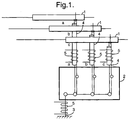
- Figure 1 represents systems of earthing without cross-bonding and may, according to the type of earthing represent the upstream or downstream end of the cable installation, its mid-point or multiple points along its length. It also represents those places in a cross-bonded installation where actual earth connections are normally made.
- the metal sheaths 1, 1, 1 of the three phases a, b, c of the installation are connected (in a conventional way) to separate terminals in a link box 2 which permits them to be connected to a common earth lead 3 (during service) or disconnected from it (for conventional testing of the oversheath).
- the individual earth leads 4 are shown as being concentric, which is the most usual way of ensuring adequate control of the very high transient voltages that may arise; however, separate leads for the two sides of the earth circuit could be used.
- optical fibre temperature sensors 5 are wrapped around, or incorporated into the metallic conductor(s) of, the common earth lead 3 and/or the individual earth leads 4 of the individual phases.
- the common earth lead 3 normally carries little or no current, and so its temperature is the most sensitive indicator of the occurrence of a fault; on the other hand, the temperatures of the individual earth conductors 4 will vary depending on the particular phase on which a fault may occur, and by making measurements on these conductors the faulted return conductor section or phase may be predicted and location of a fault after its occurrence has been detected accelerated.
- Figure 2 shows, for an installation in which the sheaths of the individual phases are sectionalised and cross-bonded, one of the cross-bonding positions.
- the sheaths 1 are individually connected to corresponding terminals of a link box 2 by individual (usually concentric) leads 4 but the terminals in the link box are interconnected so that adjacent lengths of sheath of different phases of the installation are connected in series, so balancing the installation and minimising overall sheath currents.
- Another terminal is connected to earth by a common earth lead 3, but in this case the latter is provided only for earthing the link box itself and, if sheath voltage limiters 6 are star-connected, for earthing the star point.
- optical fibre temperature detectors 5 applied to the individual conductors 4 will again give useful data allowing phase and section predictions to be made of the location of any fault detected and, alternatively or in addition, useful data can be obtained when sheath voltage transients occur from optical fibre temperature sensors 7 and 8 respectively wound on the common earth lead 3 and the sheath voltage limiters 6.
- These voltage limiters are substantially insulating under normal conditions but switch to a low resistance state at high voltages (say around 6kV), whereupon a high current may flow for a short period, producing a temperature pulse. In case of an oversheath fault, part of the pulse current will be shunted through the fault and the size of the temperature pulse will be reduced.
- thermal insulation may be used to increase temperature rise and so the sensitivity of the measurements; for example, in the examples shown in the drawings, the regions of the optical fibre wrappings may be enveloped in polyurethane foam (preferably a low-strength composition if in positions where access may be needed during testing operations or otherwise) or over-wrapped with flexible thermal insulating material.
Landscapes
- Physics & Mathematics (AREA)
- General Physics & Mathematics (AREA)
- Testing Of Short-Circuits, Discontinuities, Leakage, Or Incorrect Line Connections (AREA)
- Locating Faults (AREA)
- Cable Accessories (AREA)
Applications Claiming Priority (2)
| Application Number | Priority Date | Filing Date | Title |
|---|---|---|---|
| GB9805019 | 1998-03-11 | ||
| GBGB9805019.8A GB9805019D0 (en) | 1998-03-11 | 1998-03-11 | Method of and apparatus for detecting cable oversheath faults and installations in which they are used |
Publications (3)
| Publication Number | Publication Date |
|---|---|
| EP0942292A2 true EP0942292A2 (de) | 1999-09-15 |
| EP0942292A3 EP0942292A3 (de) | 2002-05-15 |
| EP0942292B1 EP0942292B1 (de) | 2005-06-29 |
Family
ID=10828260
Family Applications (1)
| Application Number | Title | Priority Date | Filing Date |
|---|---|---|---|
| EP99301696A Expired - Lifetime EP0942292B1 (de) | 1998-03-11 | 1999-03-08 | Gerät und Verfahren zur Erfassung von Fehlern eines Kabelisolierungsmantels und Anlagen die sie benutzen |
Country Status (6)
| Country | Link |
|---|---|
| EP (1) | EP0942292B1 (de) |
| AT (1) | ATE298892T1 (de) |
| DE (1) | DE69925946T2 (de) |
| ES (1) | ES2245075T3 (de) |
| GB (1) | GB9805019D0 (de) |
| SG (1) | SG97781A1 (de) |
Cited By (8)
| Publication number | Priority date | Publication date | Assignee | Title |
|---|---|---|---|---|
| WO2001048498A1 (en) * | 1999-11-24 | 2001-07-05 | Udaya Shankar, Srikantiaha, Rama, Rao | ELECTRICAL FLASHOVER MONITOR-E FOM?x+¿ |
| US10024724B2 (en) | 2015-11-02 | 2018-07-17 | Te Connectivity Corporation | Temperature monitoring systems and methods for electrical power distribution systems |
| CN112557856A (zh) * | 2020-12-23 | 2021-03-26 | 南方电网电力科技股份有限公司 | 高压电缆护套的监测方法、装置、存储介质及计算机设备 |
| CN112787295A (zh) * | 2021-01-06 | 2021-05-11 | 国核电力规划设计研究院重庆有限公司 | 一种分舱电缆隧道中电缆换位架设结构 |
| CN113030782A (zh) * | 2021-04-20 | 2021-06-25 | 广东电网有限责任公司 | 一种二次电缆屏蔽层接地状态监测装置及系统 |
| CN113447767A (zh) * | 2021-06-25 | 2021-09-28 | 北京英瑞来科技有限公司 | 一种高压电力电缆的金属外套故障定位方法及系统 |
| EP4067921A1 (de) * | 2021-03-29 | 2022-10-05 | Nexans | Überwachung der integrität einer hülle |
| CN116256596A (zh) * | 2023-03-16 | 2023-06-13 | 杭州柯林电气股份有限公司 | 一种电缆数据在线采集系统和方法 |
Families Citing this family (1)
| Publication number | Priority date | Publication date | Assignee | Title |
|---|---|---|---|---|
| US11150291B1 (en) * | 2021-05-14 | 2021-10-19 | Underground Systems, Inc. | Functional reliability assessment for insulated power cable systems |
Family Cites Families (10)
| Publication number | Priority date | Publication date | Assignee | Title |
|---|---|---|---|---|
| US3365665A (en) * | 1964-07-27 | 1968-01-23 | Nasa Usa | Hall current measuring apparatus having a series resistor for temperature compensation |
| JP2899806B2 (ja) * | 1988-11-22 | 1999-06-02 | 株式会社フジクラ | 電力ケーブルの事故区間検出方法 |
| US5178465A (en) * | 1990-07-11 | 1993-01-12 | Fujikura Ltd. | Optical fiber laying structure for electric power cable line trouble occurrence location detecting system |
| DE4100037C2 (de) * | 1991-01-03 | 1995-03-30 | Christian Kueck | Verfahren, einen Mantelerdschluss in einem beidseitig geerdeten, mit einem Isoliermantel umgebenen elektrisch leitfähigem Medium mit einem induktiven Meßsystem während des Betriebes festzustellen |
| JP2794237B2 (ja) * | 1991-12-13 | 1998-09-03 | 株式会社フジクラ | 電力ケーブル線路の事故区間検出方法 |
| WO1993015411A1 (fr) * | 1992-01-24 | 1993-08-05 | Mitsui Petrochemical Industries, Ltd. | Procede de prediction de courts-circuits et appareil correspondant |
| JP2946931B2 (ja) * | 1992-03-06 | 1999-09-13 | 日本電気株式会社 | 高温高湿型原子間力顕微鏡及び化学反応の観察・定量化方法 |
| JPH07298486A (ja) * | 1994-04-21 | 1995-11-10 | Okinawa Denryoku Kk | 配電線の地絡事故点認識処理装置 |
| JPH08304487A (ja) * | 1995-05-08 | 1996-11-22 | Hitachi Cable Ltd | 活線状態のケーブルシースの絶縁診断方法 |
| GB9522998D0 (en) * | 1995-11-09 | 1996-01-10 | Smiths Industries Ltd | Current sensors |
-
1998
- 1998-03-11 GB GBGB9805019.8A patent/GB9805019D0/en not_active Ceased
-
1999
- 1999-03-03 SG SG9901056A patent/SG97781A1/en unknown
- 1999-03-08 ES ES99301696T patent/ES2245075T3/es not_active Expired - Lifetime
- 1999-03-08 EP EP99301696A patent/EP0942292B1/de not_active Expired - Lifetime
- 1999-03-08 DE DE69925946T patent/DE69925946T2/de not_active Expired - Lifetime
- 1999-03-08 AT AT99301696T patent/ATE298892T1/de active
Cited By (9)
| Publication number | Priority date | Publication date | Assignee | Title |
|---|---|---|---|---|
| WO2001048498A1 (en) * | 1999-11-24 | 2001-07-05 | Udaya Shankar, Srikantiaha, Rama, Rao | ELECTRICAL FLASHOVER MONITOR-E FOM?x+¿ |
| US10024724B2 (en) | 2015-11-02 | 2018-07-17 | Te Connectivity Corporation | Temperature monitoring systems and methods for electrical power distribution systems |
| CN112557856A (zh) * | 2020-12-23 | 2021-03-26 | 南方电网电力科技股份有限公司 | 高压电缆护套的监测方法、装置、存储介质及计算机设备 |
| CN112557856B (zh) * | 2020-12-23 | 2023-10-31 | 南方电网电力科技股份有限公司 | 高压电缆护套的监测方法、装置、存储介质及计算机设备 |
| CN112787295A (zh) * | 2021-01-06 | 2021-05-11 | 国核电力规划设计研究院重庆有限公司 | 一种分舱电缆隧道中电缆换位架设结构 |
| EP4067921A1 (de) * | 2021-03-29 | 2022-10-05 | Nexans | Überwachung der integrität einer hülle |
| CN113030782A (zh) * | 2021-04-20 | 2021-06-25 | 广东电网有限责任公司 | 一种二次电缆屏蔽层接地状态监测装置及系统 |
| CN113447767A (zh) * | 2021-06-25 | 2021-09-28 | 北京英瑞来科技有限公司 | 一种高压电力电缆的金属外套故障定位方法及系统 |
| CN116256596A (zh) * | 2023-03-16 | 2023-06-13 | 杭州柯林电气股份有限公司 | 一种电缆数据在线采集系统和方法 |
Also Published As
| Publication number | Publication date |
|---|---|
| EP0942292B1 (de) | 2005-06-29 |
| ES2245075T3 (es) | 2005-12-16 |
| SG97781A1 (en) | 2003-08-20 |
| DE69925946D1 (de) | 2005-08-04 |
| EP0942292A3 (de) | 2002-05-15 |
| GB9805019D0 (en) | 1998-05-06 |
| DE69925946T2 (de) | 2006-05-11 |
| ATE298892T1 (de) | 2005-07-15 |
Similar Documents
| Publication | Publication Date | Title |
|---|---|---|
| EP0398593B1 (de) | Vorrichtung zur Anzeige übermässiger Quetschung einer Kabelanordnung gegen eine elektrisch geerdete Struktur | |
| US7005995B2 (en) | System and method for remotely detecting and locating damaged conductors in a power system | |
| RU2631025C2 (ru) | Обнаружение направления слабоустойчивого короткого замыкания на землю среднего напряжения с помощью линейной корреляции | |
| EP1669767A1 (de) | System und Verfahren zur Erdfehlerortung in einem Stromverteilungssystem | |
| KR20240026133A (ko) | 절연 전력 케이블 시스템의 기능적 신뢰성 평가 | |
| JP4566407B2 (ja) | 地下ケーブルにおける絶縁性低下を診断するための方法 | |
| US9696386B2 (en) | System and method of making an integrity test on an electricity network in an aircraft | |
| EP1843443A2 (de) | Elektrische Fehlerdetektion | |
| EP0942292B1 (de) | Gerät und Verfahren zur Erfassung von Fehlern eines Kabelisolierungsmantels und Anlagen die sie benutzen | |
| JP2992615B2 (ja) | 非接地系電路の線路定数計測装置及び地絡監視装置 | |
| US5532601A (en) | Circuit integrity test system | |
| EP4257987A1 (de) | Verfahren zum lokalisieren eines fehlerpunktes auf einem hochspannungs-drehstromkabel und system zum lokalisieren eines fehlerpunktes | |
| US20240060830A1 (en) | Method and system for detecting heating at a connector between electrical cables and connectors suitable for such a method | |
| EP4067921B1 (de) | Überwachung der integrität einer hülle | |
| EP1065510B1 (de) | Lokalisierung von intermittierenden und transienten Erdschlüssen | |
| HK1022352A (en) | Method of and apparatus for detecting cable oversheath faults and installations in which they are used | |
| Selkirk et al. | Why neutral-grounding resistors need continuous monitoring | |
| JP7341070B2 (ja) | 地絡点標定システム及びその方法 | |
| US5552712A (en) | Method for in-place circuit integrity testing | |
| RU2726046C1 (ru) | Устройство контроля системы электрообогрева промышленных объектов | |
| JPH04220573A (ja) | 低圧系統活線絶縁劣化監視方法 | |
| Gieselbrecht et al. | Monitoring of 420 kV XLPE cable system in underground tunnel | |
| de Freitas | A brief history of fault location in transmission lines | |
| Yamashita et al. | Study on Location Accuracy of Partial Discharge Locator | |
| JP2006010608A (ja) | 非接地電路の絶縁監視方法とその装置 |
Legal Events
| Date | Code | Title | Description |
|---|---|---|---|
| PUAI | Public reference made under article 153(3) epc to a published international application that has entered the european phase |
Free format text: ORIGINAL CODE: 0009012 |
|
| AK | Designated contracting states |
Kind code of ref document: A2 Designated state(s): AT BE CH DE DK ES FI FR GB GR IE IT LI LU MC NL PT SE |
|
| AX | Request for extension of the european patent |
Free format text: AL;LT;LV;MK;RO;SI |
|
| RAP1 | Party data changed (applicant data changed or rights of an application transferred) |
Owner name: PIRELLI CABLES (2000) LIMITED |
|
| PUAL | Search report despatched |
Free format text: ORIGINAL CODE: 0009013 |
|
| AK | Designated contracting states |
Kind code of ref document: A3 Designated state(s): AT BE CH DE DK ES FI FR GB GR IE IT LI LU MC NL PT SE |
|
| AX | Request for extension of the european patent |
Free format text: AL;LT;LV;MK;RO;SI |
|
| 17P | Request for examination filed |
Effective date: 20021113 |
|
| AKX | Designation fees paid |
Designated state(s): AT BE CH DE DK ES FI FR GB GR IE IT LI LU MC NL PT SE |
|
| 17Q | First examination report despatched |
Effective date: 20030926 |
|
| GRAP | Despatch of communication of intention to grant a patent |
Free format text: ORIGINAL CODE: EPIDOSNIGR1 |
|
| GRAS | Grant fee paid |
Free format text: ORIGINAL CODE: EPIDOSNIGR3 |
|
| GRAA | (expected) grant |
Free format text: ORIGINAL CODE: 0009210 |
|
| AK | Designated contracting states |
Kind code of ref document: B1 Designated state(s): AT BE CH DE DK ES FI FR GB GR IE IT LI LU MC NL PT SE |
|
| PG25 | Lapsed in a contracting state [announced via postgrant information from national office to epo] |
Ref country code: LI Free format text: LAPSE BECAUSE OF FAILURE TO SUBMIT A TRANSLATION OF THE DESCRIPTION OR TO PAY THE FEE WITHIN THE PRESCRIBED TIME-LIMIT Effective date: 20050629 Ref country code: CH Free format text: LAPSE BECAUSE OF FAILURE TO SUBMIT A TRANSLATION OF THE DESCRIPTION OR TO PAY THE FEE WITHIN THE PRESCRIBED TIME-LIMIT Effective date: 20050629 Ref country code: BE Free format text: LAPSE BECAUSE OF FAILURE TO SUBMIT A TRANSLATION OF THE DESCRIPTION OR TO PAY THE FEE WITHIN THE PRESCRIBED TIME-LIMIT Effective date: 20050629 |
|
| REG | Reference to a national code |
Ref country code: GB Ref legal event code: FG4D |
|
| REG | Reference to a national code |
Ref country code: CH Ref legal event code: EP |
|
| REF | Corresponds to: |
Ref document number: 69925946 Country of ref document: DE Date of ref document: 20050804 Kind code of ref document: P |
|
| REG | Reference to a national code |
Ref country code: IE Ref legal event code: FG4D |
|
| PG25 | Lapsed in a contracting state [announced via postgrant information from national office to epo] |
Ref country code: SE Free format text: LAPSE BECAUSE OF FAILURE TO SUBMIT A TRANSLATION OF THE DESCRIPTION OR TO PAY THE FEE WITHIN THE PRESCRIBED TIME-LIMIT Effective date: 20050929 Ref country code: GR Free format text: LAPSE BECAUSE OF FAILURE TO SUBMIT A TRANSLATION OF THE DESCRIPTION OR TO PAY THE FEE WITHIN THE PRESCRIBED TIME-LIMIT Effective date: 20050929 Ref country code: DK Free format text: LAPSE BECAUSE OF FAILURE TO SUBMIT A TRANSLATION OF THE DESCRIPTION OR TO PAY THE FEE WITHIN THE PRESCRIBED TIME-LIMIT Effective date: 20050929 |
|
| PG25 | Lapsed in a contracting state [announced via postgrant information from national office to epo] |
Ref country code: PT Free format text: LAPSE BECAUSE OF FAILURE TO SUBMIT A TRANSLATION OF THE DESCRIPTION OR TO PAY THE FEE WITHIN THE PRESCRIBED TIME-LIMIT Effective date: 20051207 |
|
| REG | Reference to a national code |
Ref country code: ES Ref legal event code: FG2A Ref document number: 2245075 Country of ref document: ES Kind code of ref document: T3 |
|
| REG | Reference to a national code |
Ref country code: CH Ref legal event code: PL |
|
| PG25 | Lapsed in a contracting state [announced via postgrant information from national office to epo] |
Ref country code: IE Free format text: LAPSE BECAUSE OF NON-PAYMENT OF DUE FEES Effective date: 20060308 |
|
| PG25 | Lapsed in a contracting state [announced via postgrant information from national office to epo] |
Ref country code: MC Free format text: LAPSE BECAUSE OF NON-PAYMENT OF DUE FEES Effective date: 20060331 Ref country code: LU Free format text: LAPSE BECAUSE OF NON-PAYMENT OF DUE FEES Effective date: 20060331 |
|
| ET | Fr: translation filed | ||
| PLBE | No opposition filed within time limit |
Free format text: ORIGINAL CODE: 0009261 |
|
| STAA | Information on the status of an ep patent application or granted ep patent |
Free format text: STATUS: NO OPPOSITION FILED WITHIN TIME LIMIT |
|
| 26N | No opposition filed |
Effective date: 20060330 |
|
| REG | Reference to a national code |
Ref country code: HK Ref legal event code: WD Ref document number: 1022352 Country of ref document: HK |
|
| REG | Reference to a national code |
Ref country code: IE Ref legal event code: MM4A |
|
| NLT1 | Nl: modifications of names registered in virtue of documents presented to the patent office pursuant to art. 16 a, paragraph 1 |
Owner name: PRYSMIAN CABLES (2000) LIMITED |
|
| REG | Reference to a national code |
Ref country code: FR Ref legal event code: CD Ref country code: FR Ref legal event code: CA |
|
| REG | Reference to a national code |
Ref country code: GB Ref legal event code: 732E |
|
| REG | Reference to a national code |
Ref country code: GB Ref legal event code: 732E |
|
| NLS | Nl: assignments of ep-patents |
Owner name: PRYSMIAN CABLES & SYSTEMS LIMITED Effective date: 20070807 |
|
| REG | Reference to a national code |
Ref country code: FR Ref legal event code: TP |
|
| REG | Reference to a national code |
Ref country code: GB Ref legal event code: 732E |
|
| REG | Reference to a national code |
Ref country code: FR Ref legal event code: PLFP Year of fee payment: 18 |
|
| REG | Reference to a national code |
Ref country code: FR Ref legal event code: PLFP Year of fee payment: 19 |
|
| REG | Reference to a national code |
Ref country code: FR Ref legal event code: PLFP Year of fee payment: 20 |
|
| PGFP | Annual fee paid to national office [announced via postgrant information from national office to epo] |
Ref country code: NL Payment date: 20180326 Year of fee payment: 20 Ref country code: FI Payment date: 20180328 Year of fee payment: 20 Ref country code: GB Payment date: 20180327 Year of fee payment: 20 |
|
| PGFP | Annual fee paid to national office [announced via postgrant information from national office to epo] |
Ref country code: FR Payment date: 20180326 Year of fee payment: 20 Ref country code: AT Payment date: 20180221 Year of fee payment: 20 Ref country code: IT Payment date: 20180322 Year of fee payment: 20 |
|
| PGFP | Annual fee paid to national office [announced via postgrant information from national office to epo] |
Ref country code: ES Payment date: 20180402 Year of fee payment: 20 Ref country code: DE Payment date: 20180328 Year of fee payment: 20 |
|
| REG | Reference to a national code |
Ref country code: DE Ref legal event code: R071 Ref document number: 69925946 Country of ref document: DE |
|
| REG | Reference to a national code |
Ref country code: NL Ref legal event code: MK Effective date: 20190307 |
|
| REG | Reference to a national code |
Ref country code: GB Ref legal event code: PE20 Expiry date: 20190307 |
|
| REG | Reference to a national code |
Ref country code: AT Ref legal event code: MK07 Ref document number: 298892 Country of ref document: AT Kind code of ref document: T Effective date: 20190308 |
|
| PG25 | Lapsed in a contracting state [announced via postgrant information from national office to epo] |
Ref country code: GB Free format text: LAPSE BECAUSE OF EXPIRATION OF PROTECTION Effective date: 20190307 |
|
| REG | Reference to a national code |
Ref country code: ES Ref legal event code: FD2A Effective date: 20220128 |
|
| PG25 | Lapsed in a contracting state [announced via postgrant information from national office to epo] |
Ref country code: ES Free format text: LAPSE BECAUSE OF EXPIRATION OF PROTECTION Effective date: 20190309 |