EP0942633A1 - ContrÔleur de lampe de polymérisation - Google Patents
ContrÔleur de lampe de polymérisation Download PDFInfo
- Publication number
- EP0942633A1 EP0942633A1 EP99102631A EP99102631A EP0942633A1 EP 0942633 A1 EP0942633 A1 EP 0942633A1 EP 99102631 A EP99102631 A EP 99102631A EP 99102631 A EP99102631 A EP 99102631A EP 0942633 A1 EP0942633 A1 EP 0942633A1
- Authority
- EP
- European Patent Office
- Prior art keywords
- control
- cable
- voltage
- light curing
- light
- Prior art date
- Legal status (The legal status is an assumption and is not a legal conclusion. Google has not performed a legal analysis and makes no representation as to the accuracy of the status listed.)
- Granted
Links
- 238000011156 evaluation Methods 0.000 claims abstract description 21
- 230000011664 signaling Effects 0.000 claims abstract description 4
- 239000005548 dental material Substances 0.000 claims abstract description 3
- 238000006116 polymerization reaction Methods 0.000 claims abstract 2
- 230000033228 biological regulation Effects 0.000 claims description 7
- 230000001105 regulatory effect Effects 0.000 claims description 7
- 238000001514 detection method Methods 0.000 claims 2
- 238000001816 cooling Methods 0.000 claims 1
- 230000005669 field effect Effects 0.000 abstract description 2
- 238000005286 illumination Methods 0.000 abstract 1
- 230000000630 rising effect Effects 0.000 abstract 1
- 239000003990 capacitor Substances 0.000 description 3
- 230000002349 favourable effect Effects 0.000 description 3
- 238000005259 measurement Methods 0.000 description 3
- 210000003462 vein Anatomy 0.000 description 3
- 238000010586 diagram Methods 0.000 description 2
- 230000006641 stabilisation Effects 0.000 description 2
- 238000011105 stabilization Methods 0.000 description 2
- RYGMFSIKBFXOCR-UHFFFAOYSA-N Copper Chemical compound [Cu] RYGMFSIKBFXOCR-UHFFFAOYSA-N 0.000 description 1
- 230000006978 adaptation Effects 0.000 description 1
- 230000005540 biological transmission Effects 0.000 description 1
- 238000011088 calibration curve Methods 0.000 description 1
- 238000006243 chemical reaction Methods 0.000 description 1
- 229910052802 copper Inorganic materials 0.000 description 1
- 239000010949 copper Substances 0.000 description 1
- 238000011161 development Methods 0.000 description 1
- 230000018109 developmental process Effects 0.000 description 1
- 238000009499 grossing Methods 0.000 description 1
- 229910052736 halogen Inorganic materials 0.000 description 1
- 150000002367 halogens Chemical class 0.000 description 1
- 238000012423 maintenance Methods 0.000 description 1
- 238000012544 monitoring process Methods 0.000 description 1
- 238000001228 spectrum Methods 0.000 description 1
- WFKWXMTUELFFGS-UHFFFAOYSA-N tungsten Chemical compound [W] WFKWXMTUELFFGS-UHFFFAOYSA-N 0.000 description 1
- 229910052721 tungsten Inorganic materials 0.000 description 1
- 239000010937 tungsten Substances 0.000 description 1
Images

Classifications
-
- H—ELECTRICITY
- H05—ELECTRIC TECHNIQUES NOT OTHERWISE PROVIDED FOR
- H05B—ELECTRIC HEATING; ELECTRIC LIGHT SOURCES NOT OTHERWISE PROVIDED FOR; CIRCUIT ARRANGEMENTS FOR ELECTRIC LIGHT SOURCES, IN GENERAL
- H05B39/00—Circuit arrangements or apparatus for operating incandescent light sources
- H05B39/04—Controlling
- H05B39/041—Controlling the light-intensity of the source
- H05B39/044—Controlling the light-intensity of the source continuously
-
- A—HUMAN NECESSITIES
- A61—MEDICAL OR VETERINARY SCIENCE; HYGIENE
- A61C—DENTISTRY; APPARATUS OR METHODS FOR ORAL OR DENTAL HYGIENE
- A61C19/00—Dental auxiliary appliances
- A61C19/003—Apparatus for curing resins by radiation
- A61C19/004—Hand-held apparatus, e.g. guns
-
- Y—GENERAL TAGGING OF NEW TECHNOLOGICAL DEVELOPMENTS; GENERAL TAGGING OF CROSS-SECTIONAL TECHNOLOGIES SPANNING OVER SEVERAL SECTIONS OF THE IPC; TECHNICAL SUBJECTS COVERED BY FORMER USPC CROSS-REFERENCE ART COLLECTIONS [XRACs] AND DIGESTS
- Y02—TECHNOLOGIES OR APPLICATIONS FOR MITIGATION OR ADAPTATION AGAINST CLIMATE CHANGE
- Y02B—CLIMATE CHANGE MITIGATION TECHNOLOGIES RELATED TO BUILDINGS, e.g. HOUSING, HOUSE APPLIANCES OR RELATED END-USER APPLICATIONS
- Y02B20/00—Energy efficient lighting technologies, e.g. halogen lamps or gas discharge lamps
Definitions
- the invention relates to a light curing device, according to the preamble of claim 1.
- Various network-based light curing devices become the light polymerisation of dental materials can be used, and in which a handheld device Light source that takes up a cable to a feed station connected is.
- Such light curing devices face battery-assisted light curing devices have the advantage that a higher light output can be provided, and that the Handheld device itself is usually lighter after the weight of one Accumulator can be omitted.
- the supply voltage for the Light source in the feed station in a known manner stabilized a voltage regulator.
- a voltage stabilization sufficient over the life of the light source, to provide sufficient light output put.
- the light output measured by the handheld device, an example of such a light curing device from the DE-GM 92 12 892 can be seen.
- the dining station equipped with a light sensor, which then should respond when the detected light is bright enough.
- Light sources for example designed as halogen lamps may be, are consumables. Still exist considerable quality differences and thus differences in the Lifespan. For example, with the same operating parameters a light source with high quality filament that is made of consist of evenly strong wire and are wound very evenly is, three times the lifespan of a less achieve high quality light source, with the known devices, the improved service life of high quality Light sources that usually also have a well-defined spectrum deliver, cannot be exploited.
- Another disadvantage of known light curing devices is that they are bad at the local peculiarities of existing Dental practices can be customized. While in some Practices would be cheaper, the dining station directly to the handheld device to be arranged adjacent so that a short cable is sufficient would be the local conditions in other practices so that a closely spaced arrangement of dining station and handheld device would be cheaper.
- the cable length must not exceed a certain length, so as not to endanger the light output to be provided.
- the cable should not be too thick to hold the not to impair desired flexibility and flexibility, so that so far mostly a very limited minimal and Maximum length for the cable is prescribed.
- the cable in the desired length and even mostly from the manufacturer. adjusts the light source control to the cable length be made so that when the spatial changes Conditions, or if it turns out that the first ordered cable length is not enough, a complex Exchange with intervention by the customer service technician in the device is required.
- the invention is therefore based on the object of a light curing device according to the preamble of claim 1 to create the offers improved economy and can be used more flexibly is.
- the light curing device according to the invention results in a significantly improved utilization of the light sources, so that it it is recommended to use high quality light sources, which have a longer life, so that the Maintenance intervals for the light curing device clearly, for example can be extended to three times the time.
- the power control according to the invention can be done here exploit particularly favorably by namely according to the invention voltage tracking according to the internal resistance of the Light source is made.
- the increase in internal resistance is automatically observed according to a preferred embodiment, signaling occurs when the voltage tracking does not match the Internal resistance can deliver more voltage, which is synonymous with the need to change the lamp is. In this case, the required target performance cannot more are given.
- This configuration allows with particular simple but also particularly effective means of lifespan monitoring, the change in the tungsten filament is adjusted so that a considerable proportion of the lifespan available per se the light source is given away.
- the power regulation is recorded directly on the Light source voltage and current, i.e. their operating parameters, and takes a regulation in the area of the dining station that the Has actuator, before.
- the cable takes an additional one Control line on, which can be kept very thin and therefore, the flexibility of the cable is not affected.
- the cable is mounted so that the plug Dentist or his assistants themselves an adjustment of the Light curing device can make to the desired cable length.
- Such cables can be offered pre-assembled, taking it when using standardized plugs and sockets it is even possible to use industrially prefabricated standard cables use that can be obtained inexpensively.
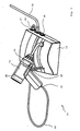
- the light curing device 10 shown in FIG. 1 has one Feeding station 12 and a handheld device 14 on a cable 16 are connected.
- the cable 16 points to his Ends plugs 18 and 20, each in respective sockets in the handheld device 14 and in the feed station 12 can be inserted.
- the socket 22 at the feed station 12 can be seen in FIG. 1.
- the cable 16 is designed as a multi-core and highly flexible cable and - as Fig. 1 shows - quite thin. His weight thus affects the handling of the handheld device 14 only in to a very limited extent, while previously used cables too with a comparatively large flexibility due to the quantities of copper used were quite heavy.
- the handheld device 14 essentially has a pistol shape and receives a light source 24 and a blower 26 which are indicated by dashed lines. There is also a start-stop switch provided, of which a power button 28 of FIG. 1st can be seen.
- the Feeding station 12 has a power switch in a manner known per se 30 on the one shown in Fig. 1 power cord 32 is supplied.
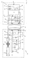
- the mains voltage is via a toroidal transformer 34 brought to secondary voltage that over a rectifier 36 rectified and via a capacitor 38 is smoothed.
- the smoothed voltage on the output side of the rectifier 36 forms an input voltage that is referred to as control bias 39, both for a Control circuit 38, described in detail below is, as well as for a fixed voltage regulator 40, the one Auxiliary supply voltage 42 already provided, which via the cable 16 is transmitted to the handheld device 14.
- the control circuit 38 has a switching regulator that is on the control bias 39 is connected and responsive to an analog control signal from a control line 44 that the Cable 16 passes through, a control element 46 switches.
- a control element 46 switches.
- the control element 46 is preferably a field effect transistor FET formed, which is connected to the control bias 39.
- the output voltage 54 of the control element 46 instructs in FIG a known manner depending on the rule requirement Impulse-pause ratio, so that essentially one There is square or trapezoidal voltage. When switched on Condition it is the control bias 39 minus the Voltage drop across the FET 46.
- Via a diode 48 can avoid a negative overshoot of the switching peaks, whereby it is understood that a corresponding to the input voltage 39 connected diode also a positive overshoot is avoidable if necessary.
- the output current of the Control element 46 is a coil 50 and something Sieve capacitor 52 smoothed so much that the output voltage 54 provided with the required low ripple and can be fed to the cable 16.
- a second power control loop directly to the switching regulator 38 formed adjacent In addition to the control loop according to the invention is preferred a second power control loop directly to the switching regulator 38 formed adjacent. With this control loop the Input current on the one providing the control bias Line and the output voltage of the control element 46 recorded and included in the regulation.
- the cable 16 is in the illustrated embodiment ten-core, but basically only four wires are sufficient.
- One vein is for the transmission of the Auxiliary supply voltage 42 determined.
- Another vein is for the control line 44 determines.
- the remaining veins are divided between the contacts for the output voltage 54 and for mass 56, in the example case four wires for each Lines are used. It is understood that here in wide areas an adjustment can be made.
- At Demand can also be on the handset side of the cable 16 another filter capacitor between output voltage 54 and Ground 56 can be switched, in which case the internal resistance of the Cable 16 also improves the smoothing of the output voltage.
- the handheld device 14 uses the auxiliary supply voltage 42 for the Power supply for an evaluation circuit 60, for the power supply of the blower 26, for the voltage supply a signaling device 62, which is designed as a piezo buzzer as well as for the power supply of an operating display LED 64.
- auxiliary elements 66 are thus out removed from the control loop and do not affect it Linearity.
- the light source 24 is via a thermal switch 68, which as Safety shutdown element is used, and via a current sensor 70 to the output voltage 54 and ground 56 on the secondary side of the cable 16, that is, in the handheld device 42.
- a current sensor 70 has a current measuring resistor with a resistance value on, which is adapted to the specified lamp power is. For example, if a lamp power of 75 watts is used the resistance of the current sensor 70 can be 0.025 ohm be.
- the voltage drop generated by the light source current The current sensor 70 detects the measuring resistor and fed to the evaluation circuit 60.
- a voltage sensor 72 which measures the terminal voltage the light source 24 is detected, and a further voltage sensor 74, which is directly connected to the output voltage 54 is connected, so that the evaluation circuit 60 also a Response of the thermal switch 68 due to a difference in Output signals of the voltage sensors 72 and 74 can detect.
- the evaluation circuit 60 forms a product of the detected voltage and current values of the sensors 70 and 72 and is to the Control line 44 connected with a corresponding Output signal is applied so that the control circuit 38th a regulation of the output voltage 54 in the feed station 12 in accordance with the performance specification of the evaluation circuit 60 makes.
- a calibration device 80 is also provided.
- the calibration device 80 comprises a start contact for the adjustment, in which the exact size of the measuring resistance of the Current sensor 70, but also the linearity of the digital / analog converter can be detected in the evaluation circuit 60.
- the calibration device 80 also includes an EEPROM, which in the Evaluation circuit 60 is included and the corresponding Saved calibration curve. The calibration can be made completely for the handheld device 14, so that they in particular regardless of the type and length of the used Cable 16 is.
- the light curing device can be operated via a start / stop button 82 start and stop with the button 82 off the power button 22 can be actuated.
- a start / stop button 82 start and stop with the button 82 off the power button 22 can be actuated.
- the type of Acquisition of the relevant voltage and current values in a wide range Areas can be adapted to the requirements.
- the Start / stop button 82 realizes a so-called soft start becomes.
- a predetermined voltage curve from the evaluation circuit 60 realized that a ramp-up of the output voltage 54 realized within 3 seconds, for example.
- the output voltage 54 is above the control voltage 84 applied to the control line 44, and it can be seen that a slope of something more than 1 is specified, which is at a threshold of 2V begins.
- the control circuit is below a control voltage of 2V 38 switched off so that when switched off Start / stop button 82 also no leakage current through the Light source 24 flows.
- current and voltage can be measured simultaneously, which also means a measurement at intervals of a few nanoseconds.
- the measurements are preferably carried out at regular time intervals, the length of which is determined by the conversion time of the digital / analog converter. It is also possible to switch the input of the converter between current and voltage measurement, and thus make do with just one converter. the messun
Landscapes
- Health & Medical Sciences (AREA)
- General Health & Medical Sciences (AREA)
- Dentistry (AREA)
- Epidemiology (AREA)
- Life Sciences & Earth Sciences (AREA)
- Animal Behavior & Ethology (AREA)
- Oral & Maxillofacial Surgery (AREA)
- Public Health (AREA)
- Veterinary Medicine (AREA)
- Dental Tools And Instruments Or Auxiliary Dental Instruments (AREA)
- Circuit Arrangement For Electric Light Sources In General (AREA)
- Heating, Cooling, Or Curing Plastics Or The Like In General (AREA)
- Endoscopes (AREA)
Applications Claiming Priority (2)
| Application Number | Priority Date | Filing Date | Title |
|---|---|---|---|
| DE19810573A DE19810573C2 (de) | 1998-03-11 | 1998-03-11 | Lichthärtgerät |
| DE19810573 | 1998-03-11 |
Publications (2)
| Publication Number | Publication Date |
|---|---|
| EP0942633A1 true EP0942633A1 (fr) | 1999-09-15 |
| EP0942633B1 EP0942633B1 (fr) | 2002-05-22 |
Family
ID=7860535
Family Applications (1)
| Application Number | Title | Priority Date | Filing Date |
|---|---|---|---|
| EP99102631A Expired - Lifetime EP0942633B1 (fr) | 1998-03-11 | 1999-02-11 | Contrôleur de lampe de polymérisation |
Country Status (5)
| Country | Link |
|---|---|
| EP (1) | EP0942633B1 (fr) |
| JP (1) | JPH11290350A (fr) |
| AT (1) | ATE218029T1 (fr) |
| CA (1) | CA2263269C (fr) |
| DE (2) | DE19810573C2 (fr) |
Families Citing this family (6)
| Publication number | Priority date | Publication date | Assignee | Title |
|---|---|---|---|---|
| US6767109B2 (en) | 2001-06-06 | 2004-07-27 | Ivoclar Vivadent Ag | Light hardening device and a light source suitable for use in a light hardening device |
| DE10127416B4 (de) * | 2001-06-06 | 2008-01-03 | Ivoclar Vivadent Ag | Lichthärtgerät sowie Lichtquelle mit einer Mehrzahl von LED's und einem Kühlkörper |
| US6835064B2 (en) | 2001-11-09 | 2004-12-28 | Ivoclar Vivadent Ag | Light hardening device and method for hardening a polymerizable mass for dental applications |
| DE10256894A1 (de) * | 2002-11-29 | 2004-06-09 | Volkswagen Ag | Verfahren und Vorrichtung zur Diagnose von Glühlampen |
| DE102006015335B4 (de) * | 2006-04-03 | 2013-05-02 | Ivoclar Vivadent Ag | Halbleiter-Strahlungsquelle sowie Lichthärtgerät |
| DE102006035657B3 (de) | 2006-07-31 | 2008-04-03 | Ivoclar Vivadent Ag | Lichtmessvorrichtung |
Citations (5)
| Publication number | Priority date | Publication date | Assignee | Title |
|---|---|---|---|---|
| EP0166364A2 (fr) * | 1984-06-28 | 1986-01-02 | ESPE Stiftung & Co Produktions- und Vertriebs KG | Dispositif destiné à l'irradiation de matériaux dentaires |
| WO1990001247A1 (fr) * | 1988-07-22 | 1990-02-08 | The D & D Electrical Group Pty Limited | Regulateur regule de c.a. |
| EP0508526A1 (fr) * | 1991-04-10 | 1992-10-14 | Koninklijke Philips Electronics N.V. | Circuit |
| US5471129A (en) * | 1992-04-03 | 1995-11-28 | Ivoclar Ag | Rechargeable light curing apparatus |
| JPH0969395A (ja) * | 1995-08-31 | 1997-03-11 | Toshiba Lighting & Technol Corp | 電源装置、放電灯点灯装置、照明装置及び液晶プロジェクタ |
Family Cites Families (3)
| Publication number | Priority date | Publication date | Assignee | Title |
|---|---|---|---|---|
| DE3605278C1 (de) * | 1986-02-19 | 1987-07-23 | Espe Pharm Praep | Schaltung zur Speisung eines dentalen Fotopolymerisationsgeraets |
| DE3840984A1 (de) * | 1988-12-06 | 1990-06-07 | Guenter Petz | Vorrichtung zum polymerisieren von halogenlichthaertenden kunststoffmaterialien |
| US5147204A (en) * | 1991-08-08 | 1992-09-15 | Minnesota Mining And Manufacturing Co. | Dental material curing apparatus |
-
1998
- 1998-03-11 DE DE19810573A patent/DE19810573C2/de not_active Expired - Fee Related
-
1999
- 1999-02-11 AT AT99102631T patent/ATE218029T1/de not_active IP Right Cessation
- 1999-02-11 DE DE59901481T patent/DE59901481D1/de not_active Expired - Fee Related
- 1999-02-11 EP EP99102631A patent/EP0942633B1/fr not_active Expired - Lifetime
- 1999-03-01 CA CA002263269A patent/CA2263269C/fr not_active Expired - Fee Related
- 1999-03-10 JP JP11064132A patent/JPH11290350A/ja active Pending
Patent Citations (5)
| Publication number | Priority date | Publication date | Assignee | Title |
|---|---|---|---|---|
| EP0166364A2 (fr) * | 1984-06-28 | 1986-01-02 | ESPE Stiftung & Co Produktions- und Vertriebs KG | Dispositif destiné à l'irradiation de matériaux dentaires |
| WO1990001247A1 (fr) * | 1988-07-22 | 1990-02-08 | The D & D Electrical Group Pty Limited | Regulateur regule de c.a. |
| EP0508526A1 (fr) * | 1991-04-10 | 1992-10-14 | Koninklijke Philips Electronics N.V. | Circuit |
| US5471129A (en) * | 1992-04-03 | 1995-11-28 | Ivoclar Ag | Rechargeable light curing apparatus |
| JPH0969395A (ja) * | 1995-08-31 | 1997-03-11 | Toshiba Lighting & Technol Corp | 電源装置、放電灯点灯装置、照明装置及び液晶プロジェクタ |
Non-Patent Citations (1)
| Title |
|---|
| PATENT ABSTRACTS OF JAPAN vol. 097, no. 007 31 July 1997 (1997-07-31) * |
Also Published As
| Publication number | Publication date |
|---|---|
| JPH11290350A (ja) | 1999-10-26 |
| DE19810573C2 (de) | 2002-09-12 |
| DE19810573A1 (de) | 1999-09-23 |
| ATE218029T1 (de) | 2002-06-15 |
| DE59901481D1 (de) | 2002-06-27 |
| CA2263269A1 (fr) | 1999-09-11 |
| EP0942633B1 (fr) | 2002-05-22 |
| CA2263269C (fr) | 2003-12-09 |
Similar Documents
| Publication | Publication Date | Title |
|---|---|---|
| DE3605278C1 (de) | Schaltung zur Speisung eines dentalen Fotopolymerisationsgeraets | |
| DE60309359T2 (de) | Methode und Schaltungsanordnung zur Regelung einer LED | |
| DE69014371T2 (de) | Schaltung zur Konstanthaltung eines Gleichstroms. | |
| DE60017203T2 (de) | Laststeuersystem zum Zuführen eines Stroms von einer AC-Quelle zu einer Last | |
| DE69227794T2 (de) | Schaltungsanordnung | |
| DE2904458A1 (de) | Drahtlose fernsteuerung fuer elektrische schweissmaschinen | |
| DE19844426A1 (de) | Gleichspannungsquelleneinheit, die einen Alarm abgibt, bevor ein elektrisch betriebenes Werkzeug überhitzt wird, und daraufhin die Stromversorgung unterbricht | |
| EP0942633B1 (fr) | Contrôleur de lampe de polymérisation | |
| DE60223845T2 (de) | Elektro-optische vorrichtung zur photopolymerisation von kunststoffmassen | |
| EP2512207A1 (fr) | Circuit d'excitation et procédé d'alimentation d'une DEL ainsi que moyen d'éclairage | |
| EP3075213B1 (fr) | Module à led | |
| DE69531757T2 (de) | Geregelte Leistungsversorgungseinheit | |
| DE102005005539B4 (de) | Energiequellenvorrichtung und Fahrzeuglampe | |
| DE2948054C3 (de) | Schaltungsanordnung zur geregelten Speisung eines Verbrauchers | |
| EP0202401B1 (fr) | Elément chauffant | |
| DE3833148A1 (de) | Hochspannungserzeuger fuer eine roentgenroehre | |
| DE19917091C1 (de) | Vorrichtung zur Einstellung der Helligkeit eines Leuchtmittels, bei welcher durch den Benutzer wählbar sowohl sprunghaftes als auch stetiges Dimmen möglich ist | |
| DE2847765C2 (de) | Schaltungsanordnung zum Schutz eines Antriebsmotors vor Überlastung, insbesondere für ein zahnärztliches Arbeitsgerät | |
| DE3205390A1 (de) | Programmierbare vorrichtung zur wartung von batterien | |
| WO2012045555A1 (fr) | Appareil de commande à température critique réglable | |
| DE3411994A1 (de) | Schaltungsanordnung fuer eine bestrahlungslampe | |
| EP0164774A1 (fr) | Dispositif de circuit pour régler la tension de l'arc dans des lampes à décharge à haute pression | |
| EP3637959B1 (fr) | Composant semi-conducteur | |
| DE3439875A1 (de) | Schaltungsanordnung zur fernspeisung elektrischer verbraucher mittels wechselspannungs-parallelspeisung | |
| WO2020152340A1 (fr) | Système d'alimentation électrique et procédé d'alimentation en énergie régulée d'au moins un consommateur électrique |
Legal Events
| Date | Code | Title | Description |
|---|---|---|---|
| PUAI | Public reference made under article 153(3) epc to a published international application that has entered the european phase |
Free format text: ORIGINAL CODE: 0009012 |
|
| AK | Designated contracting states |
Kind code of ref document: A1 Designated state(s): AT CH DE FR GB IT LI SE |
|
| AX | Request for extension of the european patent |
Free format text: AL;LT;LV;MK;RO;SI |
|
| 17P | Request for examination filed |
Effective date: 19991020 |
|
| AKX | Designation fees paid |
Free format text: AT CH DE FR GB IT LI SE |
|
| RAP1 | Party data changed (applicant data changed or rights of an application transferred) |
Owner name: IVOCLAR VIVADENT AG |
|
| GRAG | Despatch of communication of intention to grant |
Free format text: ORIGINAL CODE: EPIDOS AGRA |
|
| 17Q | First examination report despatched |
Effective date: 20010806 |
|
| GRAG | Despatch of communication of intention to grant |
Free format text: ORIGINAL CODE: EPIDOS AGRA |
|
| GRAH | Despatch of communication of intention to grant a patent |
Free format text: ORIGINAL CODE: EPIDOS IGRA |
|
| GRAH | Despatch of communication of intention to grant a patent |
Free format text: ORIGINAL CODE: EPIDOS IGRA |
|
| GRAA | (expected) grant |
Free format text: ORIGINAL CODE: 0009210 |
|
| REF | Corresponds to: |
Ref document number: 218029 Country of ref document: AT Date of ref document: 20020615 Kind code of ref document: T |
|
| REG | Reference to a national code |
Ref country code: GB Ref legal event code: FG4D Free format text: NOT ENGLISH |
|
| REG | Reference to a national code |
Ref country code: CH Ref legal event code: NV Representative=s name: KELLER & PARTNER PATENTANWAELTE AG Ref country code: CH Ref legal event code: EP |
|
| REF | Corresponds to: |
Ref document number: 59901481 Country of ref document: DE Date of ref document: 20020627 |
|
| GBT | Gb: translation of ep patent filed (gb section 77(6)(a)/1977) |
Effective date: 20020816 |
|
| ET | Fr: translation filed | ||
| PLBE | No opposition filed within time limit |
Free format text: ORIGINAL CODE: 0009261 |
|
| STAA | Information on the status of an ep patent application or granted ep patent |
Free format text: STATUS: NO OPPOSITION FILED WITHIN TIME LIMIT |
|
| 26N | No opposition filed |
Effective date: 20030225 |
|
| PG25 | Lapsed in a contracting state [announced via postgrant information from national office to epo] |
Ref country code: IT Free format text: LAPSE BECAUSE OF NON-PAYMENT OF DUE FEES;WARNING: LAPSES OF ITALIAN PATENTS WITH EFFECTIVE DATE BEFORE 2007 MAY HAVE OCCURRED AT ANY TIME BEFORE 2007. THE CORRECT EFFECTIVE DATE MAY BE DIFFERENT FROM THE ONE RECORDED. Effective date: 20050211 |
|
| PGFP | Annual fee paid to national office [announced via postgrant information from national office to epo] |
Ref country code: GB Payment date: 20070221 Year of fee payment: 9 Ref country code: AT Payment date: 20070221 Year of fee payment: 9 |
|
| PGFP | Annual fee paid to national office [announced via postgrant information from national office to epo] |
Ref country code: CH Payment date: 20070222 Year of fee payment: 9 |
|
| PGFP | Annual fee paid to national office [announced via postgrant information from national office to epo] |
Ref country code: SE Payment date: 20070223 Year of fee payment: 9 |
|
| PGFP | Annual fee paid to national office [announced via postgrant information from national office to epo] |
Ref country code: DE Payment date: 20070423 Year of fee payment: 9 |
|
| PGFP | Annual fee paid to national office [announced via postgrant information from national office to epo] |
Ref country code: FR Payment date: 20070216 Year of fee payment: 9 |
|
| REG | Reference to a national code |
Ref country code: CH Ref legal event code: PL |
|
| EUG | Se: european patent has lapsed | ||
| GBPC | Gb: european patent ceased through non-payment of renewal fee |
Effective date: 20080211 |
|
| PG25 | Lapsed in a contracting state [announced via postgrant information from national office to epo] |
Ref country code: LI Free format text: LAPSE BECAUSE OF NON-PAYMENT OF DUE FEES Effective date: 20080229 Ref country code: CH Free format text: LAPSE BECAUSE OF NON-PAYMENT OF DUE FEES Effective date: 20080229 |
|
| PG25 | Lapsed in a contracting state [announced via postgrant information from national office to epo] |
Ref country code: AT Free format text: LAPSE BECAUSE OF NON-PAYMENT OF DUE FEES Effective date: 20080211 |
|
| REG | Reference to a national code |
Ref country code: FR Ref legal event code: ST Effective date: 20081031 |
|
| PG25 | Lapsed in a contracting state [announced via postgrant information from national office to epo] |
Ref country code: SE Free format text: LAPSE BECAUSE OF NON-PAYMENT OF DUE FEES Effective date: 20080212 Ref country code: DE Free format text: LAPSE BECAUSE OF NON-PAYMENT OF DUE FEES Effective date: 20080902 |
|
| PG25 | Lapsed in a contracting state [announced via postgrant information from national office to epo] |
Ref country code: FR Free format text: LAPSE BECAUSE OF NON-PAYMENT OF DUE FEES Effective date: 20080229 |
|
| PG25 | Lapsed in a contracting state [announced via postgrant information from national office to epo] |
Ref country code: GB Free format text: LAPSE BECAUSE OF NON-PAYMENT OF DUE FEES Effective date: 20080211 |
|
| PGFP | Annual fee paid to national office [announced via postgrant information from national office to epo] |
Ref country code: IT Payment date: 20070531 Year of fee payment: 9 |
|
| PGRI | Patent reinstated in contracting state [announced from national office to epo] |
Ref country code: IT Effective date: 20091201 |
|
| PGRI | Patent reinstated in contracting state [announced from national office to epo] |
Ref country code: IT Effective date: 20091201 |